

Boss Audio 736UA User Manual

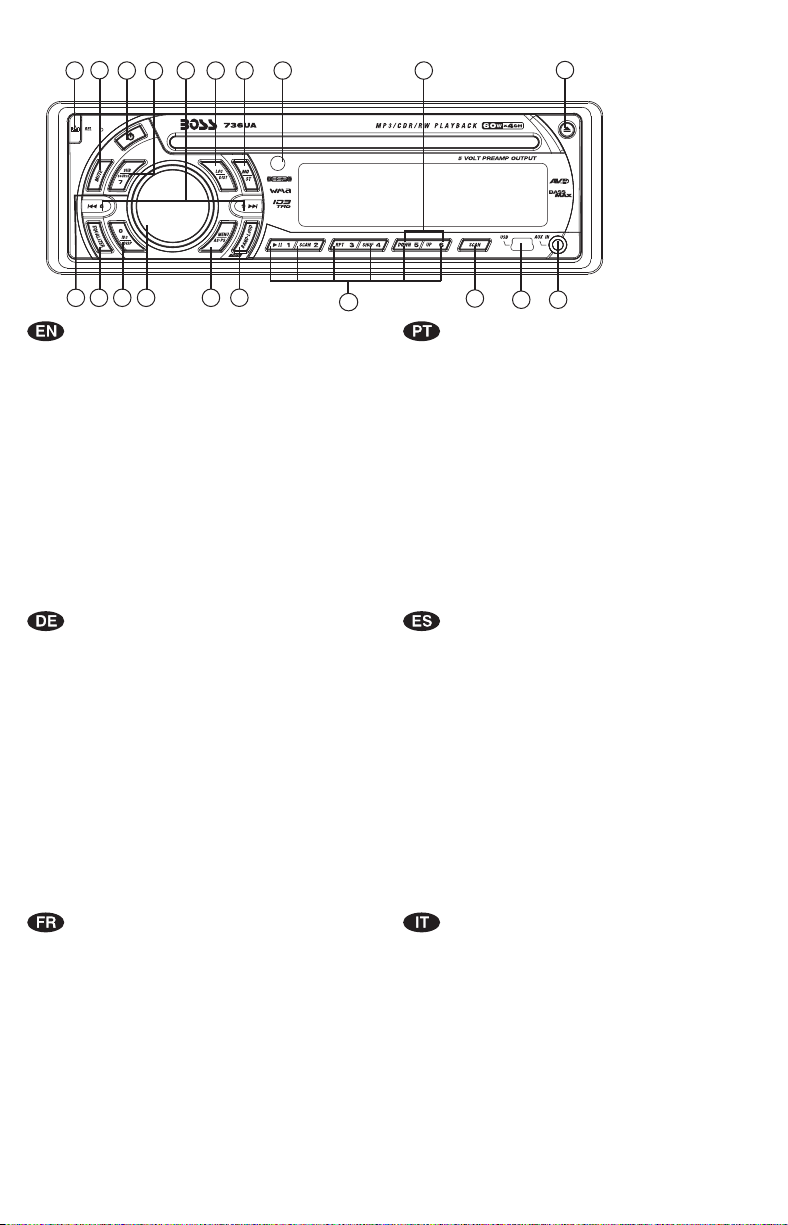
1. BUTTONS LOCATION AND FUNCTIONS
1
2
12
14
16
8
6
15
18
3
5
10
1. Panel Release Button
2. Mute Button
3. CD Eject Button
4. Audio Button
5. Display Button / ID3 Information Button
6. Local / Distant Button
7. Preset Memory Buttons
8. Mono / Stereo Button
9. Scan Button
10. Volume Knob
11. MP3 Menu Button & Automatically Store / Preset Scan Button
12. Power Button
13. Band/Loudness Button / MP3 Enter Button
14. Tuning Up/Down & Track Up / Down Buttons
15. Remote Control Receiver
16. Source Button
17. Preset Equalizer Button
18. Folder Down / Up Buttons
19. Aux In Jack
20. USB Slot
1. Entriegel-Taste Bedienteil
2. Stumm-Taste
3. CD-Auswurftaste
4. Audio-Taste
5. Display-/ ID3-Taste
6. Local / Distant-Taste
7. Senderspeichertasten
8. Mono / Stereo-Taste
9. Scan- Taste
10. Lautstärkenregler
11. AMS Taste / MP3 Suchlauf Taste
12. Einschalt-Taste
13. Frequenzband-Taste / MP3 Eingabe-Taste
14. Titel AUF / AB - Taste
15. Fernbedienungs-Taste
16. Source-Taste
17. PEQ-Taste
18. Folder Down / Up - Taste
19. Front-Audio-Anschluss
20. USB Taste
4
17
13
11
7
9
1. Tecla para remover o painel frontal
2. Tecla Mute
3. Tecla para ejetar o disco
4. Tecla de ajuste de audio
5. Tecla Display / informação MP3-iD3
6. Tecla Local/Distante
7. Teclas de memória de estações
8. Tecla estéreo/mono
9. Tecla Scan
10. Controle de volume
11. Tecla Menu e memorização automática (As) / Preset Scan (Ps)
12. Tecla Ligar/desligar
13. Tecla Banda / Loudness / MP3 Enter
14. Teclas de sintonização de estações /
15. Sensor do controle remoto
16. Tecla Source
17. Tecla Equalizador pré-programado
18. Tecla Seleção de pastas
19. Entrada Auxiliar
20. Entrada USB
1. Extracción del panel frontal
2. Mute / silenciamiento de sonido instantaneo.
3. Apertura del panel motorizado y expulsión del disco
4. Tecla Audio
5. Selección información Display/ID3 TAG muestra
6. Botón Distancia/Local
7. Botones de estaciones memorizadas
8. Botón selección mono/estéreo
9. Botón De Búsqueda
10. Botón De Volumen
11. Menú del Sistema de Memorización Automática de emisoras
/ selección de memorias
12. Encendido/Apagado
13. Selector Bandas / Bajos/MP3
14. Botón de selección de emisoras & banda de música
15. Receptor de control remoto
16. Selección modos Radio/CD/Entrada auxiliar
17. Tecla de ecualización
18. Botón de selección de carpeta/folder
19. Entrada de auxiliar
20. Entrada de USB
19
20
mudança de faixas de música
1. Bouton De Déclenchement Du Panneau
2. Bouton D'assourdissement
3. Bouton Éjection D'un Cd
4. Bouton De Sélection Audio / Entrée De MP3
5. Bouton D'écran / Affichage D'information Sur Les Disques MP3
6. Bouton Local/distant
7. Boutons Des Stations Préréglées (m1 ~m6)
8. Bouton De La Stéréo Du Mono
9. Bouton Du Scanner
10. Bouton De Volume
11. Bouton De Menu & Bouton De Stockage Des Stations Dans La Mémoire
12. Bouton D'alimentation
13. Bouton De Bande / Entrée De MP3
14. Bouton De Recherche Des Stations/pistes : En Avant / En Arrière
15. Récepteur De La Commande À Distance
16. Bouton De Régime
17. Bouton De PEQ
18. Dossier En Le Bouton/ Vers Le Haut Le Bouton
19. Aux A Jack
20. USB Slot
1
1. Tasto Rilascio Frontalino
2. Tasto Mute
3. Tasto Eject
4. Audio Controlla
5. Tasto Display/ID3 (informazioni)
6. Bottone Distante Locale
7. Tasti Stazioni Memorie Preimpostate
8. Bottone di Stereo/Mono
9. Tasto Scan
10. Tasto Volume
11. Tasto Menu & AS/PS
12. Tasto Power
13. Tasto Banda/Forte & Enter MP3
14. Tasto sintonizzazione su/gui & traccia su/gui
15. Destinatario di controllo remoto
16. Tasto Mode
17. Bottone di equilizzatore preprogrammato
18. Bottone di Cartella su/gui
19. Entrada Aux
20. Entrada USB
2. HANDLING COMPACT DISCS
MOISTURE CONDENSATION
On a rainy day or in a very damp area, moisture may condense on the lenses inside the unit. Should this
occur, the unit will not operate properly. In such a case, remove the disc and wait for about an hour until
the moisture has evaporated.
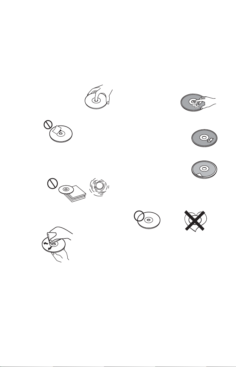
NOTES ON CDs
1.
A dirty or defective disc may cause sound
dropouts while playing. To enjoy optimum
sound, handle the disc as follows.
Handle the disc by its edge. To keep the disc
clean, do not touch the surface (P.1).
P. 1
Do not stick paper or tape on the disc (P.2).
2.
P. 2
Do not expose the discs to direct sunlight or
3.
heat sources such as hot air-ducts, or leave
them in a car parked in direct sunlight where
there can be a considerable rise in
temperature inside the car (P.3).
P. 3
4.
Before playing, clean the discs with an
optional cleaning cloth. Wipe each disc from
the center out (P.4).
P. 4
Do not use solvents such as benzine,
5.
thinner,commercially available cleaners, or
antistatic spray intended for analog discs.
NOTES ON DISCS
If you use the discs explained below, the sticky
residue can cause the CD to stop spinning and
may cause malfunction or ruin your discs.
Do not use second-hand or rental CDs that have a
sticky residue on the surface (for example, from
peeled-off stickers or from ink, or glue leaking
from under the stickers).
There are paste residue.
Ink is sticky (P.5).
P. 5
Do not use CDs with old labels that are beginning
to peel off.
Stickers that are beginning
to peel away, leaving a
sticky residue (P.6).
P. 6
Do not use your CDs with labels or stickers
attached.
Labels are attached (P.7).
Do Not Use Special Shape CDs
P. 7
Be sure to use round shape CDs only for this
unit and do not use any special shape CDs.
Use of special shape CDs may cause the unit
to malfunction.(P.8).
P. 8
Be sure to use CDs with disc mark
CD-Rs and CD-RWs which have not undergone
finalization processing cannot be played. (For
more information on finalization processing,
refer to the manual for your CD-R/CD-RW
writing software or CD-R/CD-RW recorder.)
Additionally, depending on the recording status,
it may prove impossible to play certain CDs
record on CD-R or CD-RW.
****
*******
*******
*******
*******
**************
*******
*******
*******
*******
*******
*******
*******
*******
2
3. INSTALLATION
Before finally installing the unit, connect the wiring temporarily and make sure it is all connected up
properly and the unit and system work properly.
Use only the parts included with the unit to ensure proper installation. The use of unauthorized parts
can cause malfunctions.
Consult with your nearest dealer if installation requires the drilling of holes or other modifications of the
vehicle.
Install the unit where it does not get in the driver's way and cannot injure the passenger if there is a
sudden stop, like an emergency stop.
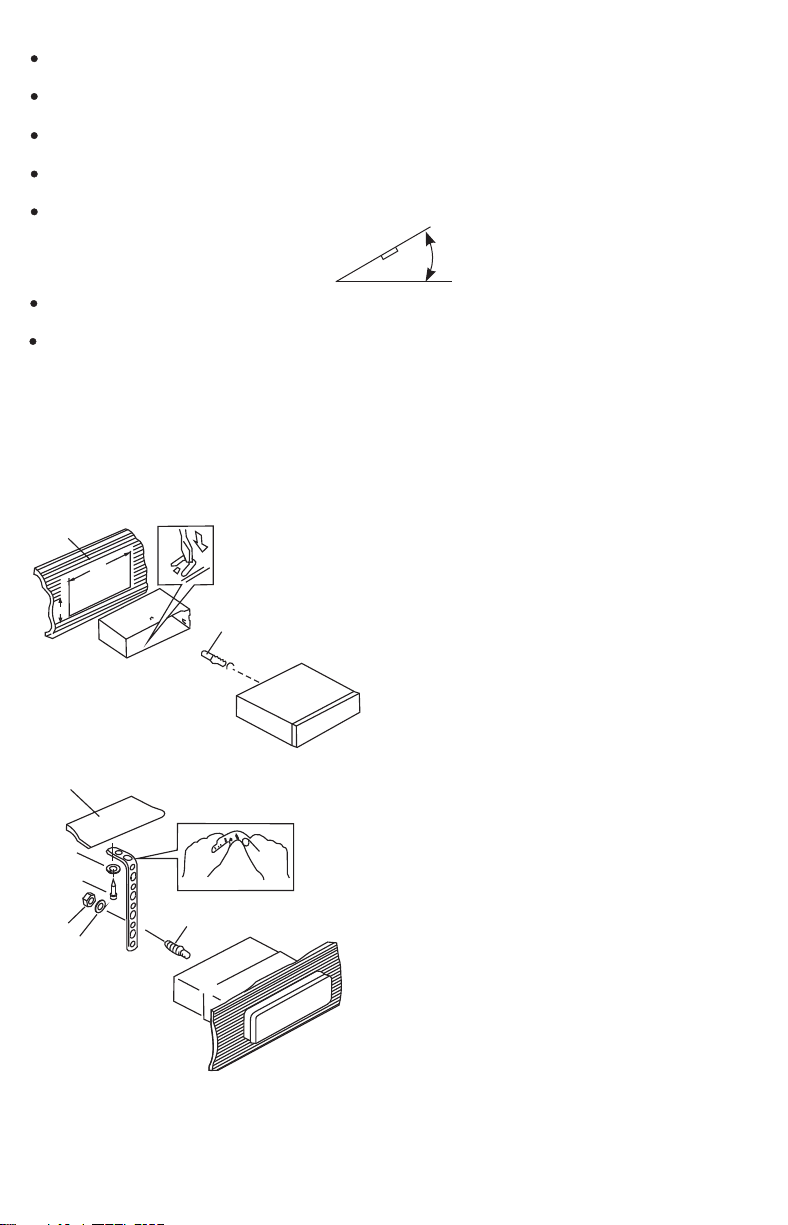
If installation angle exceeds 30° from horizontal, the unit might not give its optimum performance.
30°
Avoid installing the unit where it would be subject to high temperature, such as from direct sunlight, or
from hot air, from heater, or where it would be subject to dust dirt or excessive vibration.
Be sure to remove the front panel before installing the unit.
DIN FRONT/REAR-MOUNT
This unit can be property installed either from “Front” (conventional DIN Front-mount) or “Rear”(DIN
Rear-mount installation, utilizing threaded screw holes at the sides of the unit chassis). For details,
refer to the following illustrated installation methods A and B.
DIN FRONT-MOUNT (Method A)
Installation the unit
1
2
182
53
3
1. Dashboard
2. Holder
After inserting the half sleeve into the
dashboard, select the appropriate tab according
to the thickness of the dashboard material and
bend them inwards to secure the holder in
place.
3. Screw
1
7
4
2
3
6
5
1. Dashboard
2. Nut (5mm)
3. Spring washer
4. Screw (4x12mm)
5. Screw
6. Support Strap
Be sure to use the support strap to secure the
back of the unit in place. The strap can be bent
by hand to the desired angle.
7. Plain washer
3
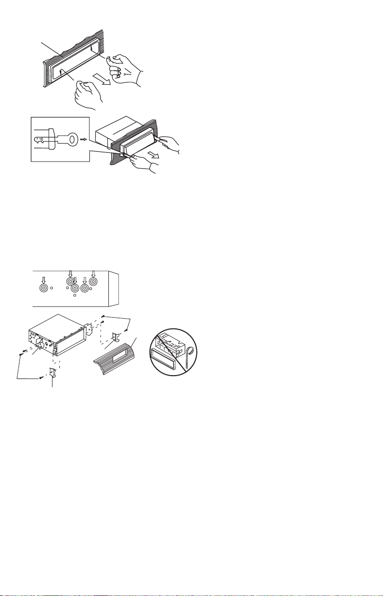
Removing the unit
a
b
c
Trim Plate Installation:
Push the trim plate against the chassis until it is fitted.
You must do this before you install the front panel, otherwise it can't be attached.
DIN REAR-MOUNT (METHOD B)
Installation using the screw holes on the sides of the unit.
Fastening the unit to the factory radio mounting bracket.
2
4
5
3
2
5
a. Frame
b. Insert fingers into the groove in the front
of frame and pull out to remove the
frame. (When re-attaching the frame,
point the side with a groove down wards
and attach it.)
c. Insert the levers supplied with the unit
into the grooves at both sides of the unit
as shown in figure until they click. Pulling
the levers makes it possible to remove
the unit from the dashboard.
1. Select a position where the screw
holes of the bracket and the screw
holes of the main unit become
aligned (are fitted) and tighten the
screws at 2 places on each side.
2. Screw
3. Factory radio mounting bracket.
4. Dashboard or Console
5. Hook (Remove this part)
Note: the mounting box, outer trim ring,
and half-sleeve are not used for method
B installation.
4
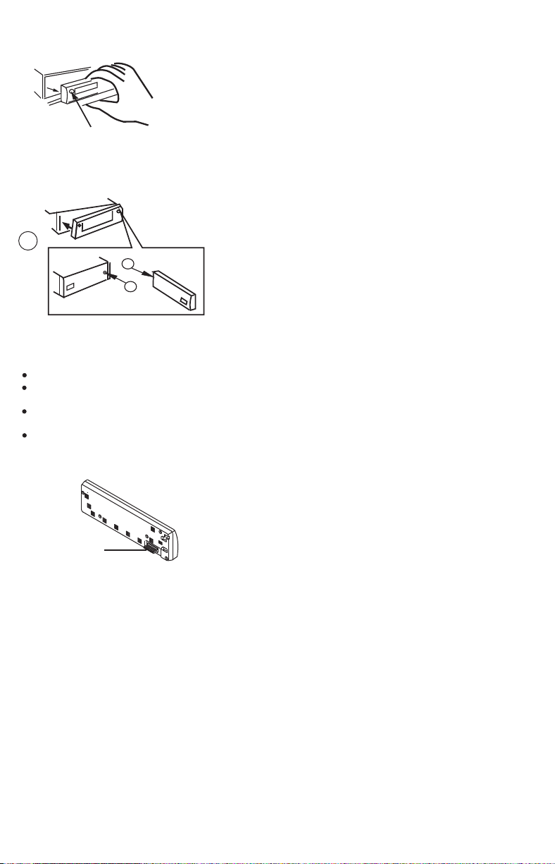
4. DETACHABLE CONTROL PANEL (D.C.P.)
Removing The Detachable Control Panel (D.C.P.).
1. Turn the power off
2. Press the D.C.P. release button
3. Remove the D.C.P.
PANEL RELEASE
BUTTON
Attaching the DCP
1. Attach the panel at the right side first, with
2
A
B
CAUTION
DO NOT insert the D.C.P from the left side. Doing so may damage it.
The D.C.P can easily be damaged by shocks. After removing it, place it in a protective case and be careful not to drop
it or subject it to strong shocks.
When the release button is pressed and the D.C.P is unlocked, the car's vibrations may cause it to fall. To prevent
damage to the D.C.P, always store it in a protective case after detaching it.
The rear connector that connects the main unit and the D.C.P is an extremely important part. Be careful not to
damage it by pressing on it with fingernails, pens, screwdrivers, etc.
point B on the main unit touching point A on
the D.C.P. (As shown on the digram).
2. Then press the left side of D.C.P. onto the main
unit until a “click” sound is heard.
Socket
Note:
If the D.C.P is dirty, wipe off the dirt with soft,
dry cloth only. And use a cotton swab soaked
in isopropyl alcohol to clean the socket on the
back of the D.C.P.
5
 Loading...