


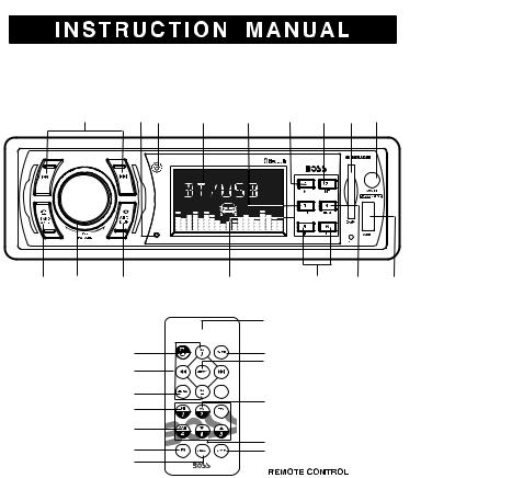
CAR MP3 PLAYER / RECEIVER WITH BLUETOOTH HAND FREE SYSTEM
TUNING /
SEEK / TRACK
UP/DOWN |
|
|
|
PLAY/ |
INTRO |
SD/MMC |
|
NEXT/BACK |
REMOTE |
LCD |
REPEAT |
PAUSE |
SCAN |
CARD |
AUX-IN |
BUTTON |
MIC SENSOR |
DISPLAY |
BUTTON |
BUTTON |
BUTTON |
SOLT |
JACK |
TALK/ |
POWER / |
CANCEL/ |
PRESET MEMORY STATION BUTTONS |
10+/- FOLDER |
RANDOM USB PORT |
BAND / |
SELECT |
SOURCE / |
(M1-M6) |
UP / DOWN |
BUTTON |
AMS |
VOLUME |
DISPLAY |
|
BUTTONS |
|
BUTTONS |
KNOB |
BUTTON |
|
|
|
TALK BUTTON
POWER BUTTON 


 MUTE BUTTON
CANCEL/SRC BUTTON
VOLUME UP / DOWN BUTTONS
MENU BUTTON
PAUSE BUTTON
SHUFFLE BUTTON
EQ BUTTON
LOUD BUTTON
C
BAND BUTTON
AUDIO BUTTON
 TUNING / SEEK/ MP3 TRACK UP/DOWN BUTTON

 AMS BUTTON
INTRO SCAN BUTTON
 REPEAT BUTTON
 PRESET MEMORY BUTTONS
10+/- FOLDER UP/DOWN BUTTONS
DISP BUTTON
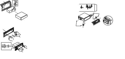
INSTALLATION
-Before finally installing the unit, connect the wiring temporarily and make sure it is all connected up properly and the unit and system work properly.
-Use only the parts included with the unit to ensure proper installation. The use of unauthorized parts can cause malfunctions. -Consult with your nearest dealer if installation requires the drilling of holes or other modifications of the vehicle.
-Install the unit where it does not get in the driver's way and cannot injure the passenger if there is a sudden stop, like an emergency stop.
-Avoid installing the unit where it would be subject to high temperature, such as from direct sunlight, or from hot air, from heater, or where it would be subject to dust dirt or excessive vibration.
DIN FRONT/REAR-MOUNT
This unit can be property installed either from Front (conventional DIN Front-mount) or Rear (DIN Rear-mount installation, utilizing threaded screw holes at the sides of the unit chassis).
For details, refer to the following illustrated installation methods A and B.
- DIN FRONT-MOUNT (Method A)
Installation the unit |
1. |
Dashboard |
1 |
2. |
Holder |
2 |
After inserting the half sleeve |
|
182 |
into the dashboard, select the |
|
|
||
53 |
appropriate tab according to the |
|
|
thickness of the dashboard |
|
|
material and bend them inwards |
|
|
to secure the holder in place. |
|
Removing the unit
a
b
c
a.Frame
b.Insert fingers into the groove in the front of frame and pull out to remove the frame. (When reattaching the frame, point the side with a groove down wards and attach it.)
c.Insert the levers supplied with the unit into the grooves at both sides of the unit as shown in figure until they click. Pulling the levers makes it possible to remove the unit from the dashboard. E - 1
- DIN REAR-MOUNT (METHOD B)
Installation using the screw holes on the sides of the unit. Fastening the unit to the factory radio mounting bracket.
2
4


 5 3
5 3 
2
5
1.Select a position where the screw holes of the bracket and the screw holes of the main unit become aligned (are fitted) and tighten the screws at 2 places on each side.
2.Screw
3.Factory radio mounting bracket.
4.Dashboard or Console
5.Hook (Remove this part)
Note: the mounting box, outer trim ring, and half-sleeve are not used for method B installation.
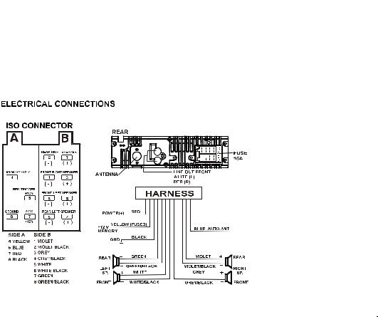
ELECTRICAL CONNECTION
a.Make sure your car battery is a 12 volt negative ground system.
b.Before starting wiring connections, disconnect the power supply by removing the fuse from fuse box at rear side.
c.Connect the power wire to one of the extra terminals of the fuse box ISO connector harness provided.
d.Connect the black ground wire to a metal part of the car. It is important to make good contact.
e.Make other wiring connections as shown. Plug ISO connector harness to ISO connector and plug fuse to fuse box at rear side.
f.If your car does not have ISO connector, you can procure it from any car accessory shop.
NOTES: INCORRECT WIRING OR OPERATION WILL AVOID THE WARRANTY OF THIS UNIT.
Fuse Replacement:
To replace the fuse, pull out the blown fuse
from the socket. Insert a new one with same rating,15A
E - 2
 Loading...