


The Bose® Lifestyle® SA-2 and SA-3 Stereo Amplifier
Owner’s Guide
Guía del usuario
Notice d’utilisation
English
Safety Information
WARNING: To reduce the risk of fire or electrical shock, do not expose the product to rain or moisture.
WARNING: The apparatus shall not be exposed to dripping or splashing, and objects filled with liquids, such as vases, shall not be placed on the apparatus. As with any electronic products, use care not to spill liquids into any part of the system. Liquids can cause a failure and/or a fire hazard.
C A U T I O N |
RISK OF ELECTRICAL SHOCK |
DO NOT OPEN |
CAUTION: TO REDUCE THE RISK OF ELECTRIC SHOCK, |
DO NOT REMOVE COVER (OR BACK). |
NO USER-SERVICABLE PARTS INSIDE. |
REFER SERVICING TO QUALIFIED PERSONNEL. |
AV I S |
RISQUE DE CHOC ÉLECTRIQUE |
NE PAS OUVRIR |
ATTENTION : POUR RÉDUIRE LE RISQUE DE DÉCHARGE |
ÉLECTRIQUE, NE RETIREZ PAS LE COUVERCLE (OU |
L’ARRIÈRE). IL NE SE TROUVE ÀL’INTÉRIEURAUCUNE |
PIÈCE POUVANT ÊTRE RÉPARÉE PARL’USAGER. |
S’ADRESSER À UN RÉPARATEUR COMPÉTENT. |
These CAUTION marks are located on the enclosure of your product:
The exclamation point within an equilateral triangle, as marked on the system, is intended to alert the user to the presence of important operating and maintenance instructions in this owner’s guide.
The lightning flash with arrowhead symbol within an equilateral triangle alerts the user to the presence of uninsulated dangerous voltage within the system enclosure that may be of sufficient magnitude to constitute a risk of electrical shock.
Class B emissions
This Class B digital apparatus meets all requirements of the Canadian Interference-Causing Equipment Regulations.
CAUTION: To prevent electric shock, match the wide blade of the line cord plug to the wide slot of the AC (mains) receptacle. Insert fully.
CAUTION: This product is not designed for use in recreational vehicle or marine applications.
WARNING: No naked flame sources, such as lighted candles, should be placed on the apparatus.
Note: The product label is located on the bottom of the product.
Please read this owner’s guide
Please take the time to follow the instructions in this owner’s guide carefully. It will help you set up and operate your system properly and enjoy all of its advanced features. Please save this owner’s guide for future reference.
©2004 Bose Corporation. No part of this work may be reproduced, modified, distributed or otherwise used without prior written permission. All trademarks referenced herein are property of Bose Corporation.
All rights reserved. Bose, Acoustimass, Lifestyle, Personal and Wave are registered trademarks of Bose Corporation.
2
Important Safety Instructions
1.Read these instructions – for all components before using this product.
2.Keep these instructions – for future reference.
3.Heed all warnings – on the product and in the owner’s guide.
4.Follow all instructions.
5.Do not use this apparatus near water or moisture – Do not use this product near a bathtub, washbowl, kitchen sink, laundry tub, in a wet basement, near a swimming pool, or anywhere else that water or moisture are present.
6.Clean only with a dry cloth – and as directed by Bose® Corporation. Unplug this product from the wall outlet before cleaning.
7.Do not block any ventilation openings. Install in accordance with the manufacturer’s instructions – To ensure reliable operation of the product and to protect it from overheating, put the product in a position and location that will not interfere with its proper ventilation. For example, do not place the product on a bed, sofa, or similar surface that may block the ventilation openings. Do not put it in a built-in system, such as a bookcase or a cabinet that may keep air from flowing through its ventilation openings.
8.Do not install near any heat sources, such as radiators, heat registers, stoves or other apparatus (including amplifiers) that produce heat.
9.Do not defeat the safety purpose of the polarized or ground- ing-type plug. A polarized plug has two blades with one wider than the other. A grounding-type plug has two blades and a third grounding prong. The wider blade or third prong are provided for your safety. If the provided plug does not fit in your outlet, consult an electrician for replacement of the obsolete outlet.
10.Protect the power cord from being walked on or pinched, particularly at plugs, convenience receptacles, and the point where they exit from the apparatus.
11.Only use attachments/accessories specified by the manufacturer.
12.Use only with the cart, stand, tripod, bracket
or table specified by the manufacturer or sold with the apparatus. When a cart is used, use caution when moving the cart/apparatus combination to avoid injury from tip-over.
13.Unplug this apparatus during lightning storms or when unused for long periods of time – to prevent damage to this product.
14.Refer all servicing to qualified service personnel. Servicing is required when the apparatus has been damaged in any way: such as power-supply cord or plug is damaged; liquid has been spilled or objects have fallen into the apparatus; the apparatus has been exposed to rain or moisture, does not operate normally, or has been dropped – Do not attempt to service this product yourself. Opening or removing covers may expose you to dangerous voltages or other hazards. Please call Bose to be referred to an authorized service center near you.
15.To prevent risk of fire or electric shock, avoid overloading wall outlets, extension cords, or integral convenience receptacles.
16.Do not let objects or liquids enter the product – as they may touch dangerous voltage points or short-out parts that could result in a fire or electric shock.
17.See product enclosure bottom for safety related markings.
18.Use Proper Power Sources – Plug the product into a proper power source, as described in the operating instructions or as marked on the product.
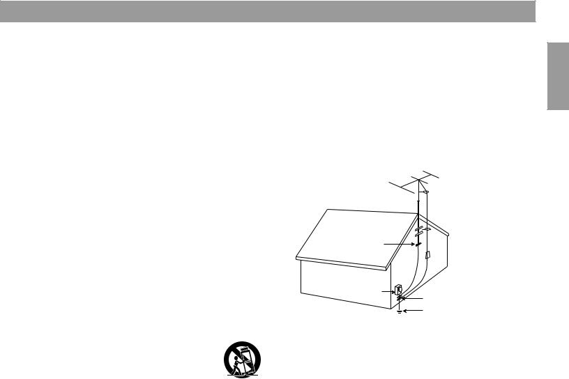
19.Avoid Power Lines – Use extreme care when installing an outside antenna system to keep from touching power lines or circuits, as contact with them may be fatal. Do not install external antennas near overhead power lines or other electric light or power circuits, nor where an antenna can fall into such circuits or power lines.
20.Ground All Outdoor Antennas – If an external antenna or cable system is connected to this product, be sure the antenna or cable system is grounded. This will provide some protection against voltage surges and built-up static charges.
Section 810 of the National Electrical Code ANSI/NFPA No. 70 provides information with respect to proper grounding of the mast and supporting structure, grounding of the lead-in wire to an antenna discharge unit, size of grounding conductors, location of antennadischarge unit, connection to grounding electrodes, and requirements for the ground electrode. Refer to the antenna grounding illustration on this page.
Antenna grounding
Example of antenna grounding as per National Electrical Code, ANSI/NFPA 70.
 Antenna lead-in wire
Ground clamp

 Antenna discharge unit
  (NEC Section 810-20)
 Grounding conductors
  (NEC Section 810-21)
Electric service |
|
equipment |
Ground clamps |
|
Power service grounding electrode system (NEC ART 250, Part H)
Note to CATV system installer
This reminder is provided to call the CATV system installer’s attention to Article 820-40 of the NEC (of USA) that provides guidelines for proper grounding. In particular, it specifies that the cable ground shall be connected to the grounding system of the building, as close to the point of cable entry as is practical.
Information about products that generate electrical noise
If applicable, this equipment has been tested and found to comply with the limits for a Class B digital device, pursuant to Part 15 of the FCC rules. These limits are designed to provide reasonable protection against harmful interference in a residential installation. This equipment generates, uses, and can radiate radio frequency energy and, if not installed and used in accordance with the instructions, may cause harmful interference to radio communications. However, this is no guarantee that interference will not occur in a particular installation. If this equipment does cause harmful interference to radio or television reception, which can be determined by turning the equipment off and on, you are encouraged to try to correct the interference by one or more of the following measures:
•Reorient or relocate the receiving antenna.
•Increase the separation between the equipment and receiver.
•Connect the equipment to an outlet on a different circuit than the one to which the receiver is connected.
•Consult the dealer or an experienced radio/TV technician for help.
Note: Unauthorized modification of the receiver or radio remote control could void the user’s authority to operate this equipment.
This product complies with the Canadian ICES-003 Class B specifications.
English
3

Français Español English
Contents |
|
Where to find… |
|
Introducing the Lifestyle® SA-2 and SA-3 Stereo Amplifier . . . . . . . . . . . . . . . . . . . . . . . . . . . . . . |
5 |
Before you begin . . . . . . . . . . . . . . . . . . . . . . . . . . . . . . . . . . . . . . . . . . . . . . . . . . . . . . . . . . . |
5 |
Unpacking the carton . . . . . . . . . . . . . . . . . . . . . . . . . . . . . . . . . . . . . . . . . . . . . . . . . . . . . . . . |
5 |
Connection panel features . . . . . . . . . . . . . . . . . . . . . . . . . . . . . . . . . . . . . . . . . . . . . . . . . . . . |
6 |
Setting Up Your Lifestyle® Stereo Amplifier . . . . . . . . . . . . . . . . . . . . . . . . . . . . . . . . . . . . . . . . . . |
8 |
Identifying your system . . . . . . . . . . . . . . . . . . . . . . . . . . . . . . . . . . . . . . . . . . . . . . . . . . . . . . |
8 |
Selecting a location for your Lifestyle® stereo amplifier . . . . . . . . . . . . . . . . . . . . . . . . . . . . . . |
9 |
Mounting your Lifestyle® stereo amplifier . . . . . . . . . . . . . . . . . . . . . . . . . . . . . . . . . . . . . . . . . |
10 |
Model AV-18/38/48 media center setup . . . . . . . . . . . . . . . . . . . . . . . . . . . . . . . . . . . . . . . . . |
11 |
Model AV-28 media center setup . . . . . . . . . . . . . . . . . . . . . . . . . . . . . . . . . . . . . . . . . . . . . . . |
13 |
Multi-room interface setup . . . . . . . . . . . . . . . . . . . . . . . . . . . . . . . . . . . . . . . . . . . . . . . . . . . . |
15 |
Model 20 music center setup . . . . . . . . . . . . . . . . . . . . . . . . . . . . . . . . . . . . . . . . . . . . . . . . . . |
17 |
Model 5 music center setup . . . . . . . . . . . . . . . . . . . . . . . . . . . . . . . . . . . . . . . . . . . . . . . . . . . |
19 |
Connecting speakers to your Lifestyle® stereo amplifier . . . . . . . . . . . . . . . . . . . . . . . . . . . . . |
21 |
Powering-up your system . . . . . . . . . . . . . . . . . . . . . . . . . . . . . . . . . . . . . . . . . . . . . . . . . . . . |
22 |
Setting Up Additional Rooms For Sound . . . . . . . . . . . . . . . . . . . . . . . . . . . . . . . . . . . . . . . . . . . . |
23 |
Setup guidelines for additional rooms . . . . . . . . . . . . . . . . . . . . . . . . . . . . . . . . . . . . . . . . . . . |
23 |
Setting up remote controls for other rooms . . . . . . . . . . . . . . . . . . . . . . . . . . . . . . . . . . . . . . . |
24 |
Setting up the amplifier room code . . . . . . . . . . . . . . . . . . . . . . . . . . . . . . . . . . . . . . . . . . . . . |
25 |
Setting Up Advanced Features . . . . . . . . . . . . . . . . . . . . . . . . . . . . . . . . . . . . . . . . . . . . . . . . . . . . |
26 |
Amplifier mode switches . . . . . . . . . . . . . . . . . . . . . . . . . . . . . . . . . . . . . . . . . . . . . . . . . . . . . |
26 |
Stereo or mono output (SA-3 only) . . . . . . . . . . . . . . . . . . . . . . . . . . . . . . . . . . . . . . . . . . . . . . |
26 |
Automatic detection of a local source (SA-3 only) . . . . . . . . . . . . . . . . . . . . . . . . . . . . . . . . . . |
26 |
Single and supplemental amplifiers . . . . . . . . . . . . . . . . . . . . . . . . . . . . . . . . . . . . . . . . . . . . . |
26 |
Maintaining Your Lifestyle® Stereo Amplifier . . . . . . . . . . . . . . . . . . . . . . . . . . . . . . . . . . . . . . . . . . |
27 |
Cleaning the amplifier . . . . . . . . . . . . . . . . . . . . . . . . . . . . . . . . . . . . . . . . . . . . . . . . . . . . . . . . |
27 |
Protecting outdoor wiring . . . . . . . . . . . . . . . . . . . . . . . . . . . . . . . . . . . . . . . . . . . . . . . . . . . . . |
27 |
Troubleshooting . . . . . . . . . . . . . . . . . . . . . . . . . . . . . . . . . . . . . . . . . . . . . . . . . . . . . . . . . . . . |
27 |
Customer service . . . . . . . . . . . . . . . . . . . . . . . . . . . . . . . . . . . . . . . . . . . . . . . . . . . . . . . . . . . |
28 |
Limited warranty . . . . . . . . . . . . . . . . . . . . . . . . . . . . . . . . . . . . . . . . . . . . . . . . . . . . . . . . . . . . |
28 |
Accessories . . . . . . . . . . . . . . . . . . . . . . . . . . . . . . . . . . . . . . . . . . . . . . . . . . . . . . . . . . . . . . . |
28 |
Technical information . . . . . . . . . . . . . . . . . . . . . . . . . . . . . . . . . . . . . . . . . . . . . . . . . . . . . . . . |
29 |
For your records
Record the model number, serial number, and purchase date. The serial number is located on the bottom panel of your Lifestyle® stereo amplifier.
Model: SA2  SA3
SA3 
Serial number: ______________________________________
Purchase date: ______________________________________
We suggest you keep your sales receipt and a copy of your product registration card together with this owner’s guide.
4
Introducing the Lifestyle® SA-2 and SA-3 Stereo Amplifier
Before you begin
Thank you for purchasing a Lifestyle® SA-2 or SA-3 stereo amplifier. The Lifestyle® stereo amplifier provides you with a simple solution when you want to add Bose® non-powered environmental speakers or Bose non-powered accessory speakers to your Lifestyle® system. Bose proprietary Integrated Signal Processing technology, featured in the amplifier, provides full, rich stereo sound, even when the speakers are playing at low volumes. By using the Lifestyle® stereo amplifier to expand your system, you can enjoy Bose quality sound and Lifestyle® system convenience in your yard, patio, swimming deck, garage, or utility room.
Unpacking the carton
WARNING: To avoid danger of suffocation, keep the plastic bags out of the reach of children.
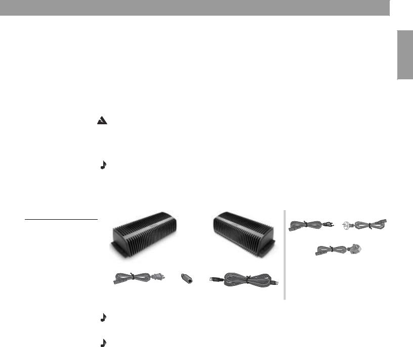
Carefully unpack the shipping carton. Make sure the shipping carton for your Lifestyle® stereo amplifier includes the parts identified in Figure 1. We recommend saving the packing materials. You may need them later. The original packing materials provide the safest way to transport this product.
Note: Locate the serial number on the bottom panel of the amplifier, and write it in the appropriate blank on page 3.
If any part of the product appears to be damaged, do not attempt to use it. Contact your authorized Bose dealer immediately, or call Bose Customer Service. Refer to the address list enclosed in the product packaging for correct phone numbers.
Figure 1
Contents of the shipping carton
SA-2 stereo |
SA-3 stereo |
amplifier |
amplifier |
120V power cord* |
8-to-9-pin |
20-ft Bose® link A cable |
USA/Canada |
DIN adapter |
Europe (230V) |
Australia (240V) |
||
|
|
|
|
|
|
|
|
|
|
|
|
UK/Singapore (230V)
*The Lifestyle® stereo amplifier includes a 120V AC (mains) power cord for use in the USA and Canada, or the appropriate 230V or 240V power cord for international use.
Note: Use only the power cord supplied with your Lifestyle® stereo amplifier. If the power cord does not fit your power (mains) outlet, DO NOT alter the plug in any way. Contact Bose Customer Service for assistance.
Note: The Lifestyle® stereo amplifier is designed for use with Bose non-powered environmental speakers or Bose non-powered accessory speakers ONLY.
English
5
English
Introducing the Lifestyle® SA-2 and SA-3 Stereo Amplifier
Connection panel features
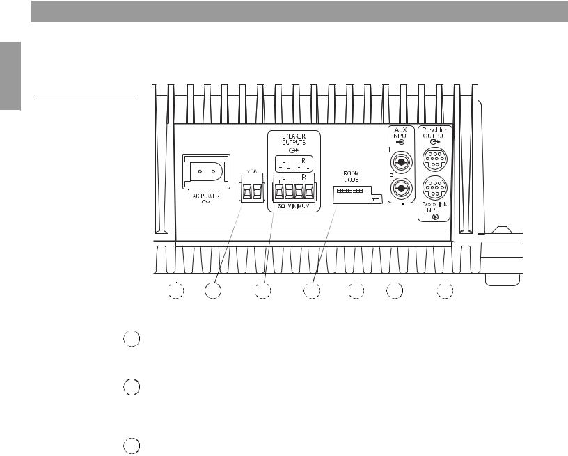
Figure 2
Lifestyle® amplifier connection panel
The connection panel includes the input/output connections plus room code switches and amplifier LED status indicators.
1 |
2 |
3 |
4 |
5 |
6 |
7 |
1AC POWER
AC power cord connector. There is no on/off switch on this product. Power is applied when the power cord is installed and plugged into an AC (mains) receptacle.
2VCA
Local volume control connections. Allows you to control the volume in a room using a wallmounted control. Contact your Bose® dealer or call Bose Customer Service for information on installing this feature. See the contact list inside the back cover of this guide.
3SPEAKER OUTPUTS
Left and right amplifier speaker outputs. A 6-ohm minimum load is required. To determine the correct speaker wire size, see “Wire recommendations” on page 29.
6
Introducing the Lifestyle® SA-2 and SA-3 Stereo Amplifier
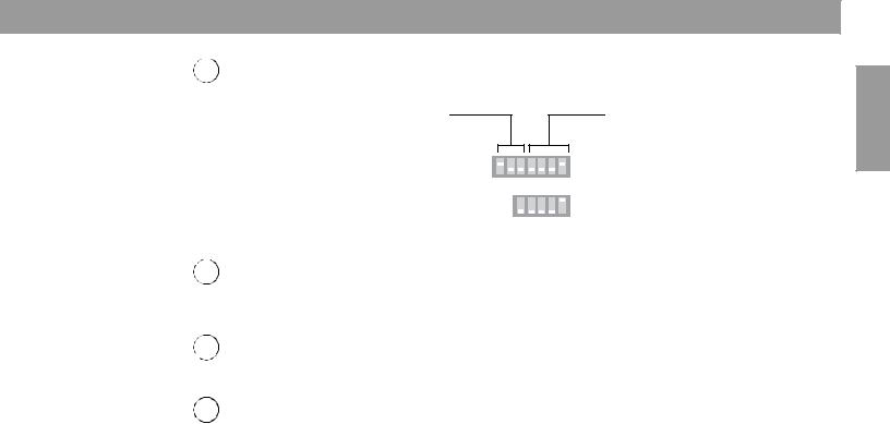
ROOM CODE switches
4Microswitches for setting room code and amplifier advanced features.
For switches A, B, and C, see “Setting Up Advanced Features” on page 26.
SA-3
A B C 6 7 8 9
SA-2
C 6 7 8 9
For switches 6 through 9, see “Setting up the amplifier room code” on page 25.
5LED status indicator
The green LED indicates the operational state of the amplifier. See “Powering-up your system” on page 22.
6AUX INPUT (SA-3 only)
Left and right channel line inputs for a local audio device.
7Bose® link INPUT/OUTPUT
Nine-pin DIN connectors used for connecting the amplifier to a Bose® link network. Input signals are passed through to the output connector to allow daisy chaining.
English
7
English
Setting Up Your Lifestyle® Stereo Amplifier
Identifying your system
The Lifestyle® stereo amplifier and additional remote come ready to be installed and used in a second room (Room B).
This section provides placement and mounting instructions for the Lifestyle® stereo amplifier. Following this information you will find a section that describes how to set up the amplifier with your particular home entertainment system.
The set of instructions you need depends on whether you have a media center, music center, or multi-room interface. The product label on the bottom panel identifies the model you have.
For the AV-18, AV-38, or AV-48 media center, see “Model AV-18/38/48 media center setup” on page 11.
For the AV-28 media center, see
“Model AV-28 media center setup” on page 13.
For the multi-room interface,
see “Multi-room interface setup” on page 15.
For the Model 20 music center,
see “Model 20 music center setup” on page 17.
For the Model 5 music center,
see, “Model 5 music center setup” on page 19.
Model AV-18/38/48 media center
Model AV-28 media center
Multi-room interface
 Model 20


 music center
Model 5 music center
Note: If you are planning to use this amplifier beyond a second room, you will need to change some switch settings in the amplifier and remote. See “Setting Up Additional Rooms For Sound” on page 23.
8

Setting Up Your Lifestyle® Stereo Amplifier
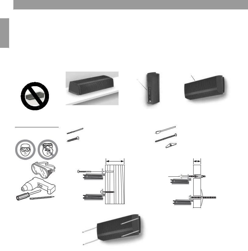
Selecting a location for your Lifestyle® stereo amplifier
Your Lifestyle® stereo amplifier does not need to be situated close to either your Lifestyle® system or the accessory speakers. Consider the following guidelines when selecting a location for your amplifier.
CAUTION: DO NOT mount the amplifier on surfaces that are not sturdy enough, or that have hazards concealed behind them, such as electrical wiring or plumbing.
CAUTION: The amplifier must be used indoors. It is neither designed nor tested for use outdoors, in recreational vehicles, or on boats.
•Locate the amplifier indoors and within 8 feet (2.5 m) of a power outlet.
•Make sure that the amplifier is located within the reach of the supplied 20-foot audio input cable.
•Place the amplifier in an area where the maximum ambient temperature is less than 104°F (45°C).
•For optimum performance, place the amplifier in a well-ventilated area.
•DO NOT place the amplifier in a completely enclosed area. If adequate ventilation is not provided, the amplifier will automatically protect itself by reducing its volume level in order to limit its temperature.
•DO NOT place the amplifier on any heat-sensitive surface, such as the finished surface of fine furniture. Like all electrical equipment, it generates some heat.
•DO NOT use the amplifier in a damp location. It is important to prevent moisture from getting into the unit.
English
9
English
Setting Up Your Lifestyle® Stereo Amplifier
Mounting your Lifestyle® stereo amplifier
Your Lifestyle® stereo amplifier can be placed on a shelf or mounted on a wall (Figure 3).
•When placing the amplifier on a horizontal surface like a floor or shelf, the amplifier’s rubber feet provide stability and prevent scratches.
•ONLY when mounting the amplifier on a wall, remove the rubber feet and use the existing guide holes in the amplifier’s enclosure for mounting hardware. See Figure 4 for recommended mounting methods and hardware.
•When mounting the amplifier vertically or horizontally on a wall, ALWAYS mount the amplifier in an orientation shown in Figure 3.
Figure 3 |
Connector |
Connector panel up |
|
panel on |
|
Installation options |
|
|
the left |
|
|
|
|
|
Shelf placement |
Vertically mounted on wall |
Horizontally mounted on wall |
|
Figure 4 |
Wood wall |
|
Wallboard |
|
|
|
|
|
|
Mounting methods and |
3/32 in (2.25 mm) |
|
1/2 in (12 mm) |
|
hardware |
|
|
(4) |
#10 x 21/2 in (M5 x 75 mm) |
|
(4) #10 x 11/2 in (M5 x 36 mm) |
|||
|
|
|
(4) |
#10 (M5) |
|
¾ in (1.9 cm) minimum |
3/8 in (0.95 cm) minimum |
||
To mark mounting hole locations, remove the rubber feet, hold the amplifier in position, and mark the wall through the clearance holes in the housing.
10
Setting Up Your Lifestyle® Stereo Amplifier
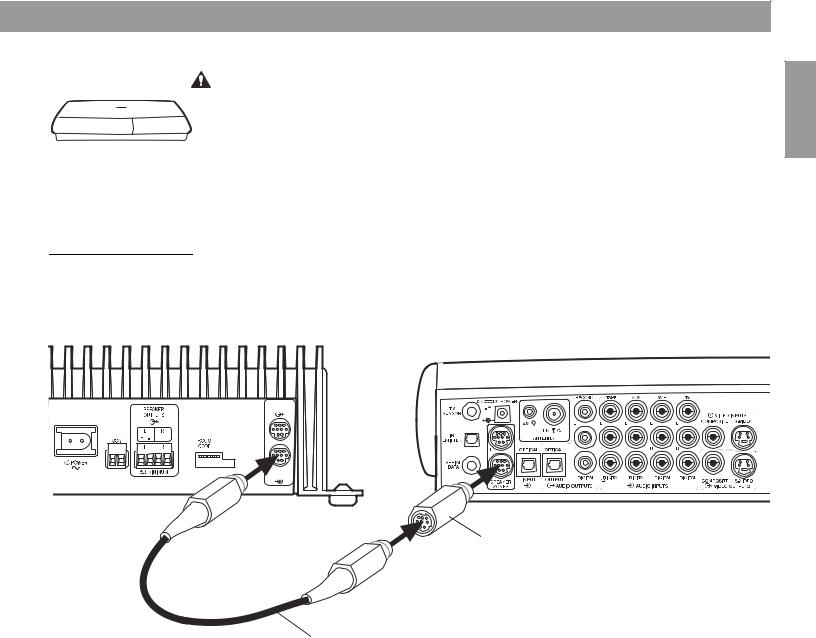
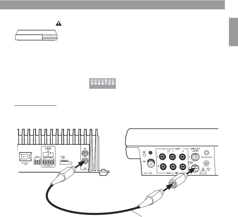
Model AV-18/38/48 media center setup
Figure 5
Lifestyle® stereo amplifier to AV-18/38/48 media center connections
CAUTION: Before making connections, turn the Lifestyle® system off and disconnect the media center from the AC (mains) power outlet. DO NOT plug the amplifier into an outlet until you have completed all other connections.
1.Insert one end of the Bose® link A cable into the Bose® link output connector on the rear panel of the media center (Figure 5).
2.Insert the other end of the Bose® link A cable, into the Bose® link input connector on the rear panel of the Lifestyle® stereo amplifier.
Lifestyle® stereo amplifier rear panel |
AV-18/38/48 media center rear panel |
|
|
|
|
English
BoseLink
OUTPUT
BoseLink
INPUT
20-ft Bose® link A cable
11
English
Setting Up Your Lifestyle® Stereo Amplifier
Figure 6
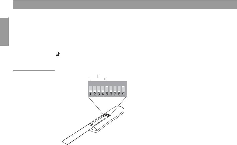
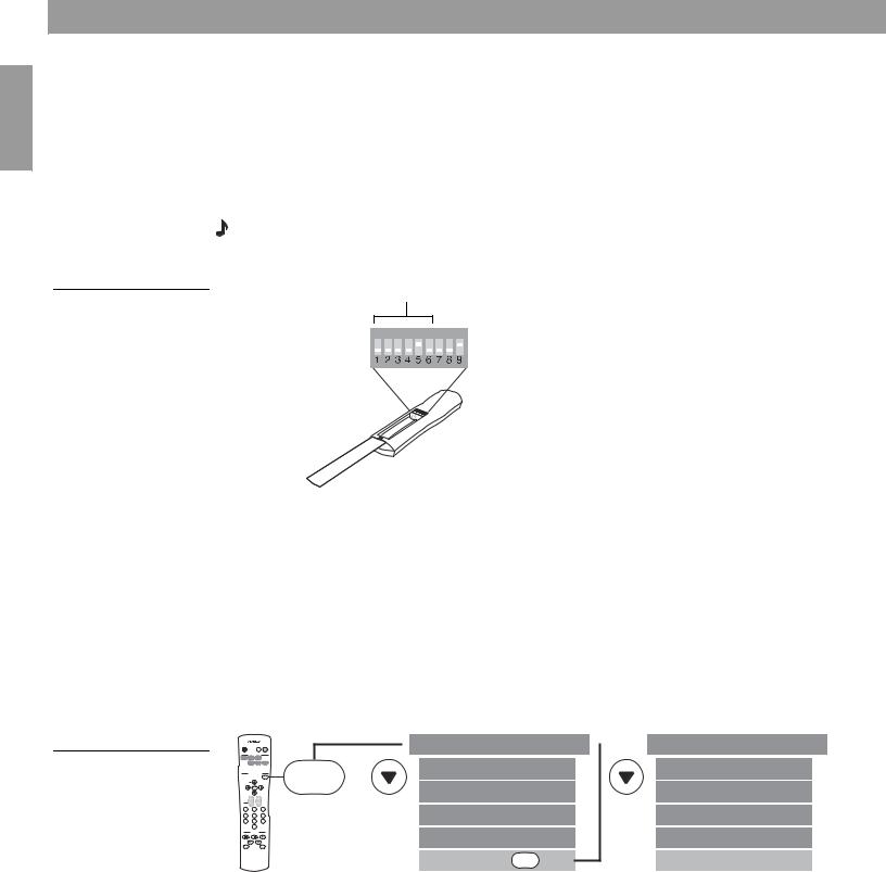
Remote microswitches
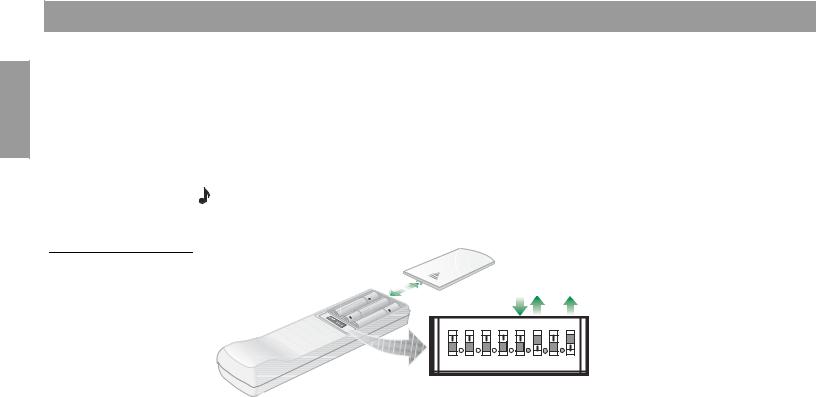
Setting up RC18S and RC38S remotes
Your additional remote is shipped from the factory already set up for a second room (room B). To make sure that this remote will work with your home entertainment system, do the following to check the house code setting.
1.Remove the remote control battery cover and locate the microswitches (Figure 6).
2.Make sure that the house code settings (switches 1, 2, 3, and 4) match the house code settings in your main room remote.
Note: If this remote is to be used beyond a second room, other switch settings will need to be changed. See “Setting Up Additional Rooms For Sound” on page 23.
House code switches must match main room remote
ON |
Check the expansion protocol setting in your system
For the Lifestyle® stereo amplifier to work properly with your home entertainment system, the expansion protocol menu item must be set to Normal. To verify this:
1.Turn on your Lifestyle® DVD home entertainment system and your TV.
2.Press the System button on your main room remote.
3.Select the Audio tab and navigate down to Expansion Protocol.
4.Verify that the setting Normal is selected. If not, select Normal now.
5.Press the Exit button on the remote.
12
Setting Up Your Lifestyle® Stereo Amplifier
Model AV-28 media center setup
Figure 7
Lifestyle® stereo amplifier to AV-28 media center connections
CAUTION: Before making connections, turn the Lifestyle® system off and disconnect the media center from the AC (mains) power outlet. DO NOT plug the amplifier into an outlet until you have completed all other connections.
1.Insert the 8-to-9-pin adapter into the SPEAKER ZONES 2 output connector on the rear panel of the media center (Figure 7).
2.Insert one end of the Bose® link A cable into the 8-to-9-pin adapter.
3.Insert the other end of the Bose® link A cable, into the Bose® link input connector on the rear panel of the Lifestyle® stereo amplifier.
Lifestyle® stereo amplifier rear panel
AV-28 media center rear panel
BoseLink
OUTPUT
BoseLink
INPUT
English
8-to-9-pin DIN adapter
20-ft Bose® link A cable
13
English
Setting Up Your Lifestyle® Stereo Amplifier
Figure 8
Remote microswitches
Setting up the RC28S remote
Your second remote is shipped from the factory already set up for Zone 2. To make sure that this remote will work with your home entertainment system, do the following to check the house code setting.
1.Remove the remote control battery cover and locate the microswitches (Figure 8).
2.Make sure that the house code settings (switches 1, 2, 3, and 4) match the house code settings in your main room remote.
3.Make sure switches 5, 7, and 8 are up, and switches 6 and 9 are down.
Note: Refer to your Lifestyle® system owner’s guide for more information on operating your system in more than one room.
House code switches must match main room remote
ON
Figure 9
Setting Zone 2 Protocol
Setting the Zone 2 Protocol in your home entertainment system
For the Lifestyle® stereo amplifier to work properly with a Lifestyle® media center, you will need to set the Zone 2 Protocol to Legacy mode (Figure 9).
1.Turn on your Lifestyle® DVD system and your TV.
2.Press the Settings button on your main room remote control.
3.Scroll down the menu to System Setup and press the Enter button.
4.Scroll down the menu to the last item, Zone 2 Protocol.
5.Press the right arrow remote button to change the protocol from Normal to Legacy.
6.Turn the system off and on again to ensure that the Zone 2 Protocol is reset to Legacy.
On |
|
Mute |
Mute |
Off |
|
All |
|
|
SOURCE / INPUT |
|
|
CD/DVD |
Changer |
FM/AM |
|
|
TV |
VCR |
AUX |
|
MENU / NAVIGATION |
||
|
|
|
Settings |
|
Tune |
|
|
|
Disc |
|
|
Seek |
Enter |
|
|
Channel |
|
|
|
Chapter |
|
|
Volume |
Preset |
|
|
|
Track |
|
|
|
1 |
2 |
|
3 |
4 |
5 |
|
6 |
7 |
8 |
|
9 |
|
0 |
|
|
|
PLAYBACK |
|
|
Stop |
Pause |
|
Play |
Shuffle |
|
|
Repeat |
 Settings ( )
Settings
System Setup |
Enter |
 System Setup (3 of 3)
Zone 2 Protocol: Legacy
14
Setting Up Your Lifestyle® Stereo Amplifier
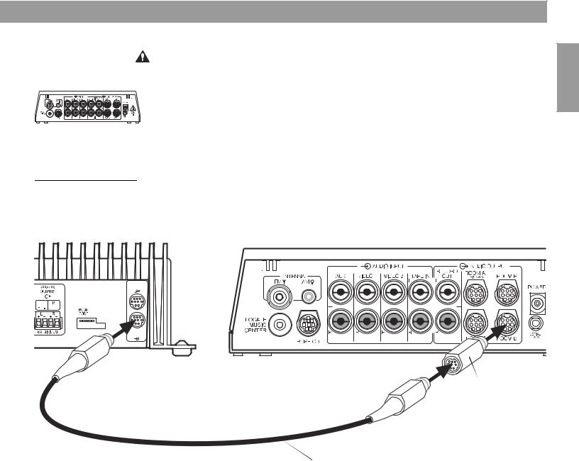
Multi-room interface setup
Figure 10
Lifestyle® stereo amplifier to multi-room interface connections
CAUTION: Before making any connections, turn the Lifestyle® system off and disconnect the music center from the AC (mains) power outlet. DO NOT plug the amplifier into an outlet until you have completed all other connections.
1. Insert the 8-to-9-pin adapter into one of the unused ROOM output connectors (B, C, or D) on the rear of the multi-room interface (Figure 10).
2. Insert one end of the Bose® link A cable into the 8-to-9-pin adapter.
3.Insert the other end of the Bose® link A cable, into the Bose® link input connector on the rear panel of the Lifestyle® stereo amplifier.
Lifestyle® stereo amplifier rear panel
Multi-room interface rear panel
BoseLink
OUTPUT
BoseLink
INPUT
English
8-to-9-pin DIN adapter
20-ft Bose® link A cable
15
English
Setting Up Your Lifestyle® Stereo Amplifier
Figure 11
Sample display for a tworoom system
Setting up the Personal® music center
Systems that have a multi-room interface are controlled by the Personal® music center which requires no internal switch settings before it allows you to control more than one room of speakers. However, if you purchase a second Personal® music center, you must follow the procedure for setting up the Personal® music center for the first time.
Note: Refer to your Lifestyle® system owner’s guide for more information on operating your system in more than one room.
Selecting other rooms with the Personal® music center
The Personal® music center allows you to control up to four sets of Bose® powered speakers placed in individual rooms. These rooms are referred to as room A, B, C, and D, with room A being the primary room (the one used for a one-room system). If two or more rooms are connected to your system, the Personal® music center displays ROOM and HOUSE buttons, and room indicators (A, B, C, and/or D). Figure 11 shows a sample display for a two-room system.
Press the ROOM button to control a single room or two or more rooms that share a source.
Press the HOUSE button to control all connected rooms as one.
The room indicators tell you what was selected by the ROOM or HOUSE button.
16
Setting Up Your Lifestyle® Stereo Amplifier
Model 20 music center setup
Figure 12
Lifestyle® stereo amplifier to Model 20 music center connections
CAUTION: Before making connections, turn the Lifestyle® system off and disconnect the music center from the AC (mains) power outlet. DO NOT plug the amplifier into an outlet until you have completed all other connections.
1. |
Insert the 8-to-9-in DIN adapter into the SPEAKER ZONES 2 output connector on the |
|
rear panel of the music center (Figure 12). |
2. |
Insert one end of the Bose® link A cable into the 8-to-9-pin adapter. |
3. |
Insert the other end of the Bose® link A cable, into the Bose® link input connector on the |
|
rear panel of the Lifestyle® stereo amplifier. |
4. |
Set the ROOM CODE switches of the Lifestyle® stereo amplifier to room E |
|
(switch 7 up, switches 6, 8 and 9 down). |
|
A B C 6 7 8 9 |
|
See “Setting up the amplifier room code” on page 25. |
Lifestyle® stereo amplifier rear panel |
Model 20 music center rear panel |
English
BoseLink
OUTPUT
BoseLink
INPUT
8-to-9-pin DIN adapter
20-ft Bose® link A cable
17
English
Setting Up Your Lifestyle® Stereo Amplifier
Setting up the RC-20 remote for Zone 2
If your system uses a Model 20 music center, you need to set up a second RC-20 remote control to operate the ZONE 2 outputs.
1.Remove the remote control battery cover and locate the miniature switches (Figure 13).
2.Make sure that the house code settings (switches 1, 2, 3, and 4) match those in your first remote.
3.Slide switch 5 down (off), and switches 6 and 8 up (on).
Note: Refer to your Lifestyle® system owner’s guide for more information on operating your system in more than one room.
Figure 13
RC-20 remote Zone 2 switch settings
ON |
|
|
|
|
|
|
K40 |
l |
2 |
3 |
4 |
5 |
6 |
7 |
8 |
18
Setting Up Your Lifestyle® Stereo Amplifier
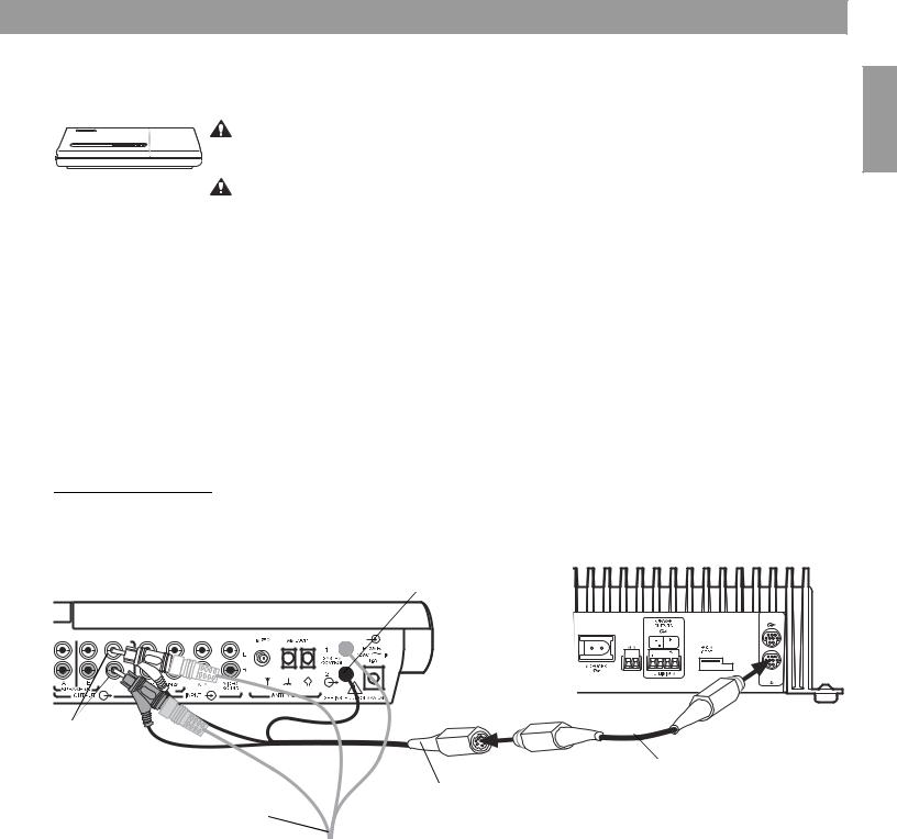
Model 5 music center setup
Figure 14
Lifestyle® stereo amplifier to Model 5 music center connections
This setup requires a 3-ft audio input adapter cable. Contact your Bose dealer or Bose® Customer Service. See the list of locations and phone numbers included in the shipping carton.
CAUTION: Before making connections, turn the Lifestyle® system off and disconnect the music center from the AC (mains) power outlet. DO NOT plug the amplifier into an outlet until you have completed all other connections.
CAUTION: DO NOT connect the audio input cable for the Lifestyle® stereo amplifier to the SPEAKERS A or SPEAKERS B outputs. The amplifier is designed to work properly with the fixed output level available from the FIXED OUTPUT connectors.
1.Disconnect the Acoustimass® cable from the FIXED L and R outputs on the rear panel of the music center (Figure 14).
2.Insert the red RCA piggyback connector of the three-foot audio input adapter cable into the R (right) FIXED OUTPUT connector. Insert the white RCA piggyback connector into the L (left) FIXED OUTPUT connector. Insert the 3.5 mm mini-plug into the SYSTEM CONTROL 2 connector on the rear panel of the music center.
3.Insert the red RCA connector of the Acoustimass module cable into the red piggyback connector and the white RCA connector into the white piggyback connector.
4.Plug one end of the 20-foot audio cable (supplied) into the free end of the three-foot audio input adapter cable. Plug the other end of the 20-foot audio cable into the Bose® link input connector on the rear panel of the Lifestyle® stereo amplifier.
Lifestyle® stereo amplifier rear panel
Model 5 music center rear panel |
SYSTEM CONTROL 2 |
|
3.5 mm mini-plug |
||
|
BoseLink
OUTPUT
BoseLink
INPUT
Fixed L and
R speaker
outputs |
20-ft Bose® link A cable |
3-ft audio input adapter
(available from Bose)
Acoustimass module cable
English
19

English
Setting Up Your Lifestyle® Stereo Amplifier
Setting up the RC-5 remote
If your system uses a Model 5 music center, you need to set up a second RC-5 remote control to operate your Lifestyle® stereo amplifier.
1.Remove the remote control battery cover and locate the miniature switches (Figure 15).
2.Make sure that the house code settings (switches 1, 2, 3, and 4) match those in your first remote.
3.Slide switch 5 down (off) and 6 up (on).
Note: Refer to your Lifestyle® system owner’s guide for more information on operating your system in more than one room.
Figure 15
RC-5 remote switch settings
ON |
|
|
|
|
|
|
K40 |
l |
2 |
3 |
4 |
5 |
6 |
7 |
8 |
20
Setting Up Your Lifestyle® Stereo Amplifier
Connecting speakers to your Lifestyle® stereo amplifier
Figure 16
Connecting speaker cable to SPEAKER OUTPUTS
CAUTION: DO NOT connect any make or model of powered speakers to the speaker outputs of the Lifestyle® stereo amplifier. Doing so may cause damage to the equipment.
CAUTION: Make sure that the amplifier is disconnected from AC power before making speaker connections.
CAUTION: The Lifestyle® stereo amplifier requires a 6-ohm minimum load.
Speaker cord consists of two insulated wires. One wire is usually marked (striped, collared, or ribbed), indicating that it should be connected to the positive (+) terminal. The plain wire should always be connected to the negative (–) terminal. For recommended wire sizes and lengths, see “Wire recommendations” on page 29.
1.Remove the terminal block connector from the SPEAKER OUTPUTS connector on the rear panel of the amplifier.
2.Connect the left speaker cord to the L positive (+) and minus (–) terminals of the 4-pin terminal block connector.
3.Connect the right speaker cord to the R positive (+) and minus (–) terminals of the 4-pin terminal block connector.
4.Plug the terminal block connector into the SPEAKER OUTPUTS connector.
Rear panel of Lifestyle® stereo amplifier
Positive (+) wire (marked with stripe)
Terminal block connector
English
21

English
Setting Up Your Lifestyle® Stereo Amplifier
Powering-up your system
CAUTION: DO NOT plug the AC power cord into an AC (mains) outlet until all other connections are complete.
1.Using the power cord included with your Lifestyle® stereo amplifier, firmly insert the small connector on one end of the power cord into the AC power connector on the rear panel of the amplifier (Figure 17).
2.Connect the power cord of the Lifestyle® stereo amplifier and your Lifestyle® music system to an AC (mains) outlet. The status LED tells you the operational status of the amplifier.
3.Select a music source with your Personal® music center or your new remote control and adjust the volume to your liking.
Figure 17 |
Rear panel of Lifestyle® stereo amplifier |
Connecting the power cord
AC power cord

|
ROOM |
Status LED |
|
CODE |
|
|
|
|
LED activity |
Meaning |
|
Constant slow blinking |
The amplifier is OFF (standby). |
|
(1 sec. on, 3 sec. off) |
|
|
|
|
|
Continuously lit |
The amplifier is ON and ready to produce sound. |
|
|
|
|
Blinking quickly |
The amplifier is ON and receiving data commands |
|
|
from the media center through the Bose® link port. |
|
|
|
|
Constant slow blinking |
The amplifier is set up as a supplemental amplifier |
|
(1 sec. on, 5 sec. off) |
and it is OFF. |
|
|
|
|
Lit but rapidly flickering |
The amplifier is set up as a supplemental amplifier |
|
|
and it is ON. |
|
|
|
|
22
Setting Up Additional Rooms For Sound
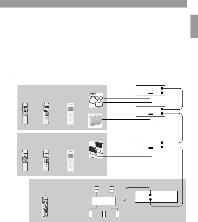
Setup guidelines for additional rooms
If you have a Lifestyle® 18 series II, 28 series II, 38 or 48 home entertainment system, you can experience stereo sound in up to 14 other rooms using Lifestyle® stereo amplifiers, compatible speaker systems and remote controls for the other rooms.
•Remote controls for other rooms must be set to the same house code as the main room remote, but each remote must be set to a different room code. See “Setting up remote controls for other rooms” on page 24.
•The Lifestyle® amplifier and its remote control must be set to the same room code. See “Setting up the amplifier room code” on page 25.
•When using more than one amplifier to power more than two speakers in a room (Figure 18, room C), all amplifiers must be set to the same room code. Also, one amplifier must be set to the single amp mode and all others must be set to the supplemental amp mode. See “Single and supplemental amplifiers” on page 26.
Figure 18
Sample installation of
Lifestyle® stereo amplifiers
ROOM C – Patio |
|
|
Freespace |
® |
Switch settings: |
SA-3 |
|
OUT |
|||
|
|
51 |
• Room code C |
|
|||||||
RC18S |
RC38S |
speakers |
|
L R |
|
||||||
Personal® |
|
• Supplemental |
|
|
IN |
||||||
Remote OR |
Remote |
OR Music Center |
|
amp |
|
|
|
||||
Control |
Control |
II |
|
|
|
|
|
||||
|
|
|
|
|
|
|
|
Switch settings: |
SA-3 |
|
OUT |
|
|
|
|
|
|
251® speakers |
• Room code C |
|
|||
|
|
|
|
|
|
|
L R |
||||
|
|
|
|
|
|
|
IN |
||||
7 |
8 |
9 |
7 |
8 |
9 |
|
|
• Single amp |
|
||
1 |
2 |
3 |
1 |
2 |
3 |
|
|
|
|
|
|
4 |
5 |
6 |
4 |
5 |
6 |
|
|
|
|
|
|
|
0 |
|
|
0 |
|
|
|
|
|
|
|
|
|
|
Remote Room Code = C |
|
|
|
|
|
|
|
|
|||||
ROOM B – Bedroom |
|
|
|
191 speakers |
|
|
|
|
|
|||||||
RC18S |
|
RC38S |
|
Personal |
® |
|
Switch settings: |
SA-2 |
|
|
||||||
OR |
OR |
|
|
|
|
|
OUT |
|||||||||
Remote |
Remote |
Music Center |
|
|
|
• Room code B |
|
L R |
||||||||
Control |
|
Control |
|
II |
|
|
|
|
|
IN |
||||||
|
|
|
|
|
|
• Single amp |
|
|||||||||
|
|
|
|
|
|
|
|
|||||||||
1 |
2 |
3 |
|
1 |
2 |
3 |
|
|
|
|
|
|
|
|
|
|
4 |
5 |
6 |
|
4 |
5 |
6 |
|
|
|
|
|
|
|
|
|
|
7 |
8 |
9 |
|
7 |
8 |
9 |
|
|
|
|
|
|
|
|
|
|
|
0 |
|
|
|
0 |
|
|
|
|
|
|
|
|
|
|
|
|
|
|
Remote Room Code = B |
|
|
|
|
|
|
|
|
|||||
|
|
|
ROOM A – Home Theater |
|
Left |
|
Right |
|
|
|
||||||
|
|
|
|
|
|
|
|
|
|
Surround |
Surround |
|
|
|
||
|
|
|
Lifestyle® system |
|
|
|
|
|
|
|
|
|
||||
|
|
|
remote control |
|
|
|
|
|
|
Main |
|
Media Center |
||||
|
|
|
|
|
|
|
|
|
|
|
|
|
|
|
|
|
|
|
|
|
|
|
|
|
|
|
|
Acoustimass® |
Bose® link |
|
|
||
|
|
|
|
|
|
|
|
|
|
|
Module |
|
|
|
|
|
|
|
|
|
|
|
|
|
|
|
Left |
Center |
Right |
|
|
|
|
English
23
English
Setting Up Additional Rooms For Sound
Setting up remote controls for other rooms
To set up the RC18S or RC38S remote:
1.Remove the remote control battery cover and locate the microswitches (Figure 19).
2.Make sure that the house code settings (switches 1, 2, 3, and 4) match the house code settings in your main room remote.
3.This remote is shipped from the factory set for room B. If this remote is used beyond a second room, set switches 6, 7, 8, and 9 to the same room code as set in the Lifestyle® stereo amplifier.
Note: Refer to your Lifestyle® system owner’s guide for more information on operating your system in more than one room.
Figure 19 |
ON |
|
||
|
|
|
|
|
|
|
|
|
|
Microswitch settings for RC18S and RC38S remotes
Room |
Room |
ON |
ON |
|
|
|
|
|
|
|
|
|
|
|
|
|
|
|
|
|
B |
|
|
|
|
|
|
|
|
|
|
|
|
|
|
|
|
|
I |
ON |
ON |
C |
J |
RC18S or RC38S |
ON |
ON |
remote |
|
|
|
|
|
|
|
D |
|
|
|
|
|
|
|
K |
|
|
|
|
|
|
|
|||||||||
|
|
|
|
|
|
|
|
||||||||
|
|
|
|
|
|
|
|
|
|
|
|
||||
|
|
|
|
|
|
|
|
|
|
|
|
||||
|
|
|
|
|
|
|
|
|
|
|
|
|
|
|
|
ON |
|
ON |
E |
L |
|
|
|
|
|
|
|
|
|
|
|
|
|
|
|
|
|
|
|
|
|
|
ON |
|
|
|
|
|
|
|
ON |
|
|
|
|
|
|
|
|
|
|
|
|
|
|
|
|
|
|
|
F |
|
|
|
|
|
|
|
|
|
|
|
|
|
|
|
|
|
|
|
M |
|
|
|
|
|
|
|
|
|
|
|
|
|
|
|
|
|
|
|
|
|
|
|
|
|
|
|
|
|
|
|
|
|
|
|
|
|
|
ON |
ON |
|
|
|
|
|
|
|
|
|
|
|
|
|
|
|
|
|
G |
|
|
|
|
|
|
|
|
|
|
|
|
|
|
|
|
|
N |
ON |
ON |
|
|
|
|
|
|
|
|
|
|
|
|
|
|
|
|
|
H |
|
|
|
|
|
|
|
|
|
|
|
|
|
|
|
|
|
O |
To set up the Personal® Music Center II:
Refer to the owner’s guide included with the Personal® music center II for instructions on configuring this remote for other rooms.
24
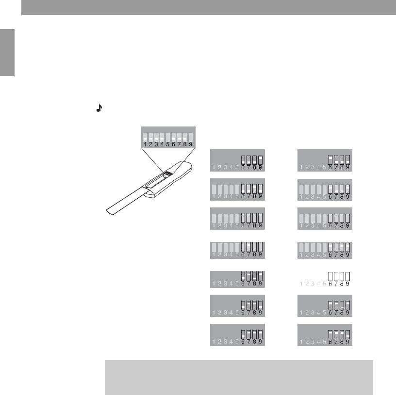
Setting Up Additional Rooms For Sound
Setting up the amplifier room code
Figure 20
Amplifier room code settings
The room code of the amplifier must match the room code of the remote used in the room where the speakers are installed.
Room code switches
SA-3 |
|
|
|
A B C 6 |
7 |
8 |
9 |
SA-2 |
|
|
|
C 6 |
7 |
8 |
9 |
|
|
|
|
|
|
|
|
|
|
|
|
|
|
|
Room |
|
|
|
|
|
|
|
|
|
|
|
|
|
|
Room |
|
|
|
|
|
|
|
|
|
|
|
|
|
|
|
|
B |
|
|
|
|
|
|
|
|
|
|
|
|
|
|
|
I |
|
|
|
|
|
|
|
|
|
|
|
|
|
|
|
|
|
|
|
|
|
|
|
|
|
|
|
|
|
|
||
|
|
|
|
|
|
|
|
|
|
|
|
|
|
|
|
|
|
|
|
|
|
|
|
|
|
|
|
|
|
||
|
A B C 6 7 8 9 |
|
|
A B C 6 7 8 9 |
|
||||||||||||||||||||||||||
|
|
|
|
|
|
|
|
|
|
|
|
|
|
|
C |
|
|
|
|
|
|
|
|
|
|
|
|
|
|
|
J |
|
|
|
|
|
|
|
|
|
|
|
|
|
|
|
|
|
|
|
|
|
|
|
|
|
|
|
|
|
|
||
|
|
|
|
|
|
|
|
|
|
|
|
|
|
|
|
|
|
|
|
|
|
|
|
|
|
|
|
|
|
||
|
A B C 6 7 8 9 |
|
|
A B C 6 7 8 9 |
|
||||||||||||||||||||||||||
|
|
|
|
|
|
|
|
|
|
|
|
|
|
|
|
|
|
|
|
|
|
|
|
|
|
|
|
|
|
|
|
|
|
|
|
|
|
|
|
|
|
|
|
|
|
|
D |
|
|
|
|
|
|
|
|
|
|
|
|
|
|
|
K |
|
A B C 6 7 8 9 |
|
|
A B C 6 7 8 9 |
|
||||||||||||||||||||||||||
|
|
|
|
|
|
|
|
|
|
|
|
|
|
|
E |
|
|
|
|
|
|
|
|
|
|
|
|
|
|
|
L |
|
|
|
|
|
|
|
|
|
|
|
|
|
|
|
|
|
|
|
|
|
|
|
|
|
|
|
|
|
|
||
|
|
|
|
|
|
|
|
|
|
|
|
|
|
|
|
|
|
|
|
|
|
|
|
|
|
|
|
|
|
||
|
A B C 6 7 8 9 |
|
|
A B C 6 7 8 9 |
|
||||||||||||||||||||||||||
|
|
|
|
|
|
|
|
|
|
|
|
|
|
|
F |
|
|
|
|
|
|
|
|
|
|
|
|
|
|
|
M |
|
|
|
|
|
|
|
|
|
|
|
|
|
|
|
|
|
|
|
|
|
|
|
|
|
|
|
|
|
|
||
|
|
|
|
|
|
|
|
|
|
|
|
|
|
|
|
|
|
|
|
|
|
|
|
|
|
|
|
|
|
||
|
A B C 6 7 8 9 |
|
|
A B C 6 7 8 9 |
|
||||||||||||||||||||||||||
|
|
|
|
|
|
|
|
|
|
|
|
|
|
|
G |
|
|
|
|
|
|
|
|
|
|
|
|
|
|
|
N |
|
|
|
|
|
|
|
|
|
|
|
|
|
|
|
|
|
|
|
|
|
|
|
|
|
|
|
|
|
|
||
|
|
|
|
|
|
|
|
|
|
|
|
|
|
|
|
|
|
|
|
|
|
|
|
|
|
|
|
|
|
||
|
A B C 6 7 8 9 |
|
|
A B C 6 7 8 9 |
|
||||||||||||||||||||||||||
|
|
|
|
|
|
|
|
|
|
|
|
|
|
|
H |
|
|
|
|
|
|
|
|
|
|
|
|
|
|
|
O |
|
|
|
|
|
|
|
|
|
|
|
|
|
|
|
|
|
|
|
|
|
|
|
|
|
|
|
|
|
|
||
|
|
|
|
|
|
|
|
|
|
|
|
|
|
|
|
|
|
|
|
|
|
|
|
|
|
|
|
|
|
||
|
A B C 6 7 8 9 |
|
|
A B C 6 7 8 9 |
|
||||||||||||||||||||||||||
|
|
|
|
|
|
|
|
|
|
|
|
|
|
|
|
|
|
|
|
|
|
|
|
|
|
|
|
|
|
|
|
English
25

English
Setting Up Advanced Features
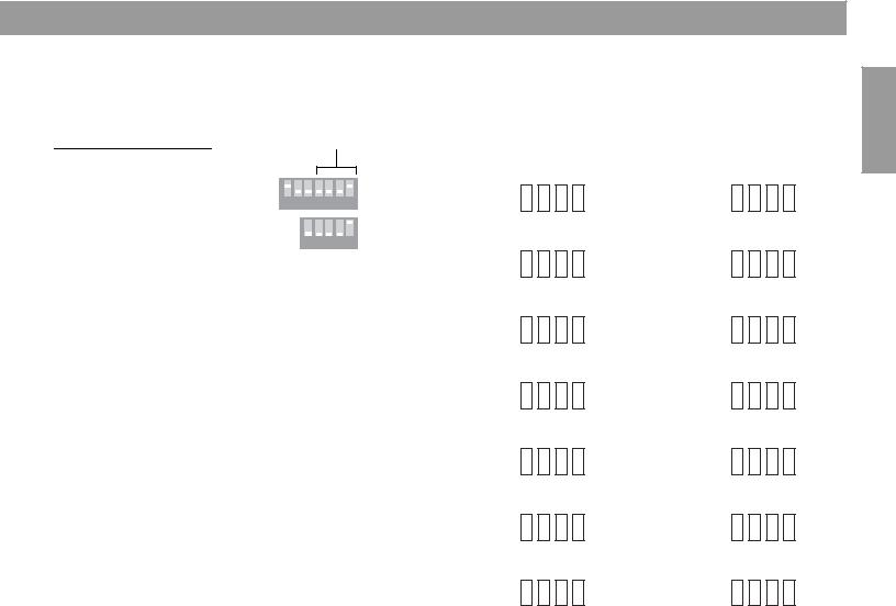
Amplifier mode switches
Figure 21
SA-2 and SA-3 microswitches
The advanced features of the Lifestyle® stereo amplifier are set up using microswitches A, B, and C (Figure 21). The SA-3 has all three switches, but the SA-2 has only switch C.
|
|
|
|
|
|
|
|
|
|
|
|
|
|
|
Switch |
Position |
Function |
|
|
|
|
|
|
|
|
|
|
|
|
|
|
|
A |
Down |
Mono output |
|
|
|
|
|
|
|
|
|
|
|
|
|
|
|
|||
|
|
|
|
|
|
|
|
|
|
|
|
|
|
|
|
Up* |
Stereo output |
|
|
|
|
|
|
|
|
|
|
|
|
|
|
|
B |
Down* |
Local source auto detect Off |
|
|
|
|
|
|
|
|
|
|
|
|
|
|
|
|||
|
|
|
|
|
|
|
|
|
|
|
|
|
|
|
|
Up |
Local source auto detect On |
|
|
|
|
|
|
|
|
|
|
|
|
|
|
|
C |
Down* |
Single amp |
|
|
|
|
|
|
|
|
|
|
|
|
|
|
|
|||
|
|
|
|
|
|
|
|
|
|
|
|
|
|
|
|
Up |
Supplemental amp |
|
|
|
|
|
|
|
|
|
|
|
|
|
|
|
|
||
SA-3 |
|
|
|
|
|
|
|
|
|
|
|
|
|
|
|
*Factory setting |
|
|
|
A B C 6 7 8 9 |
|
|
|
|
|||||||||||
SA-2
C 6 7 8 9
Stereo or mono output (SA-3 only)
The output of the SA-3 amplifier can be set to stereo (switch A up – factory setting) or mono (switch A down). The mono output mode feeds left and right channel audio to both the left and right outputs. This mode is useful in situations where a stereo output isn’t feasible such as when outdoor speakers are used in a large area.
Automatic detection of a local source (SA-3 only)
When a source is connected to the AUX INPUT connectors, you can set the amplifier to detect when that source is turned on, thereby automatically switching the amplifier from standby to on.
The amplifier is shipped with this feature turned off. For local source automatic detection, set switch B up.
Single and supplemental amplifiers
If you want to cover a large area, such as an outdoor patio, requiring more than one set of speakers, you can install additional amplifiers. See the setup for room C in “Setup guidelines for additional rooms” on page 23.
•Leave switch C down (factory setting – single amp mode) on one amplifier and set switch C up (supplemental amp mode) on all other amplifiers.
•Set the room code in all amplifiers to the same room code as in the remote control.
•Now, you can turn them all on and off, change their volumes, or mute them together using a single remote control.
26

Maintaining Your Lifestyle® Stereo Amplifier
Cleaning the amplifier
CAUTION: Disconnect the power cord from the AC outlet before cleaning.
The amplifier, which is designed only for indoor use, may become dusty over time. To clean the amplifier, use only a soft, dry cloth to remove dust from the outside of the enclosure. You may use a brush attachment on a vacuum cleaner to clean the hard-to-reach areas. DO NOT use any solvents, chemicals, or cleaning solutions containing alcohol, ammonia, or abrasives.
Protecting outdoor wiring
Although some Bose® speakers are designed and tested to stand up to outdoor weather conditions, the bare ends of the speaker wire can be affected by exposure to the elements. This is especially true of salt water exposure.
You may use a silicone caulking material, such as RTV adhesive, to protect speaker wire connections. It is commonly available at hardware stores. If you do use caulking, apply it only after the wires are connected and the knobs tightened down. Check the caulking annually, and re-apply as needed.
Troubleshooting
If you have a problem operating your Lifestyle® system after installing the Lifestyle® stereo amplifier, follow the guidelines below. For additional help, see the troubleshooting information in your system owner’s guide. If the problem still exists, contact your Bose dealer to arrange for service, or contact Bose Customer Service. Refer to the address list enclosed in the product packaging for correct phone numbers.
Problem |
What to do |
|
|
|
|
Neither speaker |
• |
Make sure the Lifestyle® media/music center and the amplifier are plugged in and turned on. |
plays |
• |
Make sure the plugs are inserted fully and the outlets are in working order. |
|
• Be sure a music source is selected (AM, FM, CD, AUX, etc.). If CD or AUX is selected, check to be sure there |
|
|
|
is a CD in the player or the source connected to AUX is turned on. |
|
• |
If using a Model 20 music center, make sure the audio input cable is inserted into SPEAKER ZONE 2. |
|
• If using a Model 5 music center for home theater (Lifestyle® 12 or Lifestyle® 8 systems), make sure the |
|
|
|
amplifier audio input cable is plugged into the FIXED OUTPUT connectors on the music center. (Then the |
|
|
speaker output cable to the Acoustimass® module should be connected to the piggyback connectors on the |
|
|
audio input cable.) |
|
• |
Disconnect any headphones. |
|
• Make sure the remote control switch settings are correct. |
|
|
|
|
Only one speaker |
• |
Check the wires connected to the speaker that does not play. |
plays |
• |
Make sure the wires are in good condition and are firmly connected at both ends. |
|
• See “Connecting speakers to your Lifestyle® stereo amplifier” on page 21. |
|
|
|
|
One speaker still |
• |
Disconnect the wires from that speaker and the amplifier. Disconnect the other cable from its speaker, and |
does not play |
|
connect that end of the cable to the speaker that does not play. If the speaker still does not play, the prob- |
|
|
lem is in the speaker. If the speaker now plays, continue checking for the source of the problem. |
|
• Disconnect the same cable from the amplifier. Connect it to the other outputs on the amplifier. If the speaker |
|
|
|
plays, the problem is in the original cable that was connected to that speaker. If the speaker does not play, |
|
|
the problem is in that channel of the amplifier. |
|
|
|
Right and left stereo |
• |
Check the speaker cable connections to be sure the cable connected to the SPEAKER OUTPUTS L at the |
channels are heard |
|
amplifier are connected at the other end to the speaker on the left in your listening area. |
on the wrong speak- |
• |
Check the speaker cable connections to be sure the cable connected to the SPEAKER OUTPUTS R at the |
ers. |
|
amplifier are connected at the other end to the speaker on the right in your listening area. |
|
|
|
English
27
 Loading...