


3•2•1® GS SERIES III 3•2•1 SERIES III
DVD HOME ENTERTAINMENT SYSTEM
Owner’s Guide Guía de usario Notice d’utilisation
Svenska |
Nederlands |
FrançaisItliano |
DeutschEspañol |
English |
|
|
|
|
|
SAFETY INFORMATION
Please read this owner’s guide
Please take the time to follow this owner’s guide carefully. It will help you set up and operate your system properly and enjoy all of its advanced features. Save this owner’s guide for future reference.
WARNING: To reduce the risk of fire or electric shock, do not expose the system to rain or moisture.
WARNING: Do not expose this apparatus to dripping or splashing, and do not place objects filled with liquids, such as vases, on or near the apparatus. As with any electronic product, use care not to spill liquids in any part of the system.
Liquids can cause a failure and/or a fire hazard.
Class 1 laser product
CLASS 1 LASER PRODUCT
KLASSE 1 LASER PRODUKT
LUOKAN 1 LASER LAITE
KLASS 1 LASER APPARAT
This CD player is classified as a CLASS 1 LASER PRODUCT according to EN 60825-1:1994+A1+A2, IEC60825-1:1993+A1+A2.
 CAUTION: Use of controls or adjustments or performance of procedures other than those specified herein may result in hazardous radiation exposure. The DVD player should not be adjusted or repaired by anyone except properly qualified service personnel.
The CAUTION marks shown here are located on the bottom of your 3•2•1® home entertainment system media center and the rear panel of the
Acoustimass® module:
The lightning flash with arrowhead symbol within an equilateral triangle alerts the user to the presence of uninsulated, dangerous voltage within the system enclosure that may be of sufficient magnitude to constitute a
risk of electric shock.
The exclamation point within an equilateral triangle alerts the user to the presence of important operating and maintenance instructions in this owner’s guide.
 CAUTION: To prevent electric shock, match wide blade of plug to wide slot, insert fully.
 CAUTION: Do not place any naked flame sources, such as lighted candles, on or near the apparatus.
Class B emissions limits
This Class B digital apparatus meets all requirements of the Canadian Interference-Causing Equipment Regulations.
 Batteries
Please dispose of used batteries properly, following any local regulations. Do not incinerate.
This product conforms to the EMC Directive 2004/108/EC and to the Low Voltage Directive 2006/95/EC. The complete Declaration of Conformity can be found at: www.Bose.com/static/compliance/index.html.
Additional safety information
See the additional instructions on the Important Safety Information sheet enclosed in the shipping carton.
ii

English |
|
DeutschEspañol |
FrançaisItliano |
Nederlands |
Svenska |
|
|
|
|
|
|
CONTENTS
INTRODUCTION |
2 |
|
|
Before you begin . . . . . . . . . . . . . . . . . . . . . . . . . |
2 |
|
For your records . . . . . . . . . . . . . . . . . . . . . . . . |
3 |
|
Unpacking . . . . . . . . . . . . . . . . . . . . . . . . . . . . . . |
4 |
SETUP |
6 |
|
1 |
Placing the system components 6 |
|
2 |
Connecting the speakers to the module . . . . . . . |
8 |
3 |
Connecting the module to the media center . . . . |
10 |
4 |
Connecting the system video to your TV . . . . . . |
12 |
5 |
Connecting a cable box or other component . . . |
17 |
|
To connect another component . . . . . . . . . . . . . |
19 |
|
To get digital audio from the component . . . . . |
20 |
|
To use video pass through . . . . . . . . . . . . . . . . |
21 |
6 |
Connecting audio from your TV as an option 22 |
|
7 |
Installing the FM and AM radio antennas . . . . . . |
25 |
8 |
Connecting the module to a power outlet . . . . . . |
28 |
9 |
Setting the remote to control your TV |
|
|
and components . . . . . . . . . . . . . . . . . . . . . . . . . |
30 |
|
Inserting the remote batteries . . . . . . . . . . . . . . |
30 |
|
Setting the remote for your TV . . . . . . . . . . . . . |
31 |
|
Controlling another component . . . . . . . . . . . . |
32 |
FIRST-TIME USE |
33 |
Trying out the DVD . . . . . . . . . . . . . . . . . . . . . . . . |
33 |
CONTROLS AND INDICATORS |
34 |
The remote control . . . . . . . . . . . . . . . . . . . . . . . . |
34 |
Power and source buttons . . . . . . . . . . . . . . . . |
35 |
Menu and movement buttons . . . . . . . . . . . . . . |
36 |
Play and numeric buttons . . . . . . . . . . . . . . . . . |
37 |
Record and A, B, C buttons |
|
(not in Europe) . . . . . . . . . . . . . . . . . . . . . . . . . . |
38 |
Colored buttons |
|
(in Europe only) . . . . . . . . . . . . . . . . . . . . . . . . . |
38 |
The media center . . . . . . . . . . . . . . . . . . . . . . . . . |
39 |
Display . . . . . . . . . . . . . . . . . . . . . . . . . . . . . . . . |
39 |
Disc tray . . . . . . . . . . . . . . . . . . . . . . . . . . . . . . . |
39 |
OPERATION |
40 |
Playing a video disc or CD . . . . . . . . . . . . . . . . . . 40 Selecting a play option . . . . . . . . . . . . . . . . . . . 40 Keeping your discs clean . . . . . . . . . . . . . . . . . 41 Checking for disc compatibility . . . . . . . . . . . . . 42 For DVDs: Setting Parental Control . . . . . . . . . . 42
Choosing a password . . . . . . . . . . . . . . . . . . . . . 42 Setting a restriction level . . . . . . . . . . . . . . . . . . 43 Ratings supplied by the MPAA . . . . . . . . . . . . . . 43
iii

Svenska |
Nederlands |
FrançaisItliano |
DeutschEspañol |
English |
|
|
|
|
|
|
|
|
|
|
|
|
|
|
|
Playing a cable box or other component . . . . . . . 44 Adjusting for audio delay . . . . . . . . . . . . . . . . . 44 Getting digital audio from a source . . . . . . . . . 45 Choosing other options . . . . . . . . . . . . . . . . . . 45
Listening to the radio . . . . . . . . . . . . . . . . . . . . . . 46 Creating a preset . . . . . . . . . . . . . . . . . . . . . . . 46 Removing a station from a preset . . . . . . . . . . . 46
ADJUSTMENTS TO THE PERFORMANCE |
47 |
Changing system features . . . . . . . . . . . . . . . . . . 47 To get to the System menu . . . . . . . . . . . . . . . . 47 Selecting a new option . . . . . . . . . . . . . . . . . . . 48 Language choices . . . . . . . . . . . . . . . . . . . . . . 48
Audio options . . . . . . . . . . . . . . . . . . . . . . . . . . |
49 |
Video options . . . . . . . . . . . . . . . . . . . . . . . . . . |
50 |
Media center options . . . . . . . . . . . . . . . . . . . . |
52 |
Choosing new settings . . . . . . . . . . . . . . . . . . . |
53 |
To get to the Settings menu . . . . . . . . . . . . . . . |
53 |
Settings options . . . . . . . . . . . . . . . . . . . . . . . |
54 |
REFERENCE |
59 |
Replacing remote batteries . . . . . . . . . . . . . . . . . . 59
Protecting the system . . . . . . . . . . . . . . . . . . . . . . 59 Cleaning the media center . . . . . . . . . . . . . . . . . 59 Cleaning the speakers . . . . . . . . . . . . . . . . . . . . 59
Troubleshooting . . . . . . . . . . . . . . . . . . . . . . . . . . |
60 |
For customer service . . . . . . . . . . . . . . . . . . . . . . |
63 |
Limited warranty . . . . . . . . . . . . . . . . . . . . . . . . . . |
63 |
Technical information . . . . . . . . . . . . . . . . . . . . . . |
64 |
COPYRIGHT AND LICENSE PROTECTIONS |
69 |
DEVICE CODES |
A-1 |
iv

Svenska |
Nederlands |
FrançaisItalino |
DeutschEspañol |
English |
|
|
|
|
|
INTRODUCTION
Before you begin
Thank you for purchasing the 3•2•1® DVD home entertainment system. Using Bose® proprietary signal processing technology, the 3•2•1 system provides improved spaciousness from stereo recordings and bold movie effects for surround-sound sources.
System features include:
•Small, easy-to-place shelf speakers
•Easy-to-hide Acoustimass® module
•Integrated DVD/CD player and AM/FM tuner
•Remote and media center controls
•HDMI video connection to your TV
•Audio In connectors for three components
•Your choice of language for text displays
2
English |
DeutschEspañol |
FrançaisItliano |
Nederlands |
Svenska |
INTRODUCTION
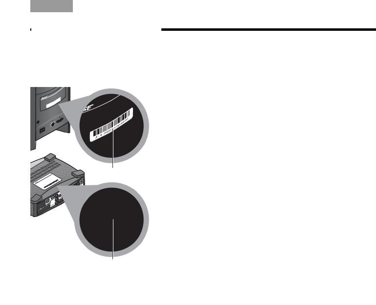
For your records
As you unpack the system, look for the serial numbers on the rear of the Acoustimass® module and the bottom of the media center.
Acoustimass module serial number
Media Center serial number
This is a good time to record the serial numbers on the lines below and on your product registration card. You may need them if you ever contact Bose® Customer Service.
Acoustimass module serial number:
________________________________________________
Media center serial number:
_______________________________________________
Dealer name:
________________________________________________
Dealer phone:
________________________________________________
Purchase date:
________________________________________________
We suggest you keep your sales receipt and the warranty information (on the product registration card) together with this owner’s guide.
3
Svenska |
Nederlands |
FrançaisItliano |
DeutschEspañol |
English |
|
|
|
|
|
INTRODUCTION
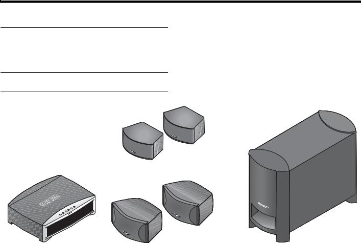
Unpacking
Carefully unpack your system. Save all packing materials, which provide the safest way to transport your system. Make sure your system includes the
parts shown.
WARNING: To avoid danger of suffocation, keep the plastic bags out of the reach of children.
As you identify them, you may want to place a check mark in the box next to the name of each part.
If any part of the system appears damaged, do not try to use it. Notify Bose or your authorized Bose® dealer right away. For contact information, refer to the address sheet included in the carton.
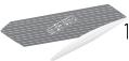
3•2•1® GS speakers
|
|
|
|
|
|
|
|
|
Acoustimass® module |
|
|
|
|
|
|
|
|
|
|
|
|
|
|
|
|
|
|
|
|
|
|
|
|
|
|
|
|
|
|
|
|
|
|
|
|
|
|
|
|
|
|
|
|
|
|
|
|
|
|
|
|
|
|
|
|
|
|
|
|
|
|
|
|
|
|
|
|
|
|
|
|
|
|
|
|
|
|
|
|
|
|
|
|
|
|
|
|
|
|
|
|
|
|
|
|
|
|
|
|
|
|
|
|
|
|
|
|
|
|
Media center |
3•2•1 speakers |
|
|||||||
4
English |
DeutschEspañol |
FrançaisItliano |
Nederlands |
Svenska |
|
|
|
|
|
INTRODUCTION
|
|
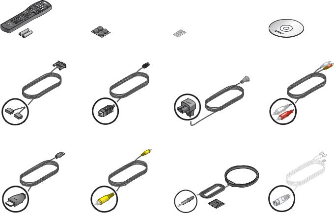
Rubber feet for speakers |
Setup disc |
|
|
|
|
||
Remote control and batteries Rubber feet for |
|
|||
|
Acoustimass® module |
|
|
|
Speaker cable |
|
Acoustimass module |
Acoustimass module |
Stereo audio cable |
||
|
|
|
|
cable |
power cord |
|
|
|
|
|
|
|
|
|
|
|
|
|
|
|
|
|
|
|
|
|
|
|
|
|
|
|
|
|
|
|
|
|
|
|
|
HDMI video cable |
Composite video cable |
AM antenna and stand |
FM antenna |
5
SETUP
Placing 1 thecomponentssystem
What you need to use:
Media center
Svenska |
Nederlands |
FrançaisItliano |
DeutschEspañol |
English |
|
|
|
|
|
|
|
|
|
|
|
|
|
|
|
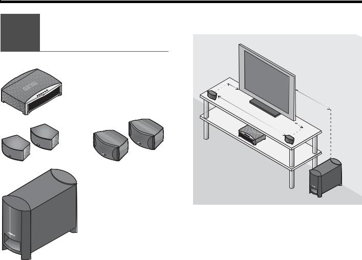
The image below shows one of the many ways you can position your new 3•2•1® system.
|
( |
o |
1 |
|
ore
|
OR |
Left |
|
|
|
|
|
speaker |
Speakers |
|
Speakers |
Right speaker
Acoustimass® module
See Steps 1-6 for details.
6
English |
DeutschEspañol |
FrançaisItliano |
Nederlands |
Svenska |
|
|
|
|
|
SETUP
1.On the bottom of each speaker, attach one set of small rubber feet.
2.Place the left and right speakers:
•at least 3 feet (1 meter) apart
•within 3 feet (1 meter) of the TV screen
•near the front edge of any shelf
•aimed straight ahead (not angled) to face the listening area
3.On the legs of the Acoustimass® module, attach the large rubber feet.
4.Place the Acoustimass module:
•at the same end of the room as the speakers and your TV
•at least 3 feet (1 meter) from the TV to prevent interference with the screen
•several feet (.8 meters) from audio or video tapes to prevent magnetic damage to them
•standing upright, not lying on a side, the front, or the back
•with the front port aimed out from or along a wall for balanced performance
•hidden under a table, behind a sofa or chair, or behind drapes as preferred
•NOT in an enclosure, on a bed, on a sofa, or on a surface that can block the ventilation openings.
CAUTION: Do not block ventilation openings on the bottom and rear of the module.
5. Place the media center:
• where nothing obstructs the front panel
• near any components you will connect
6.Continue with 2 on the next page.
7
Svenska |
Nederlands |
FrançaisItliano |
DeutschEspañol |
English |
|
|
|
|
|
SETUP
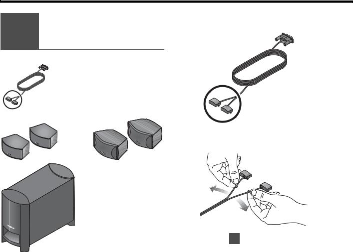
Connecting 2 the speakers
to the module
What you need to use:
1.Notice the two plugs at one end of the speaker cable.
Speaker cable
|
OR |
2. Separate the two plugs so each one reaches a |
|
speaker. |
|
|
|
|
Speakers |
|
Speakers |
Acoustimass® module
(Refer to 1 for placement guidelines.)
8
English |
DeutschEspañol |
FrançaisItliano |
Nederlands |
Svenska |
SETUP
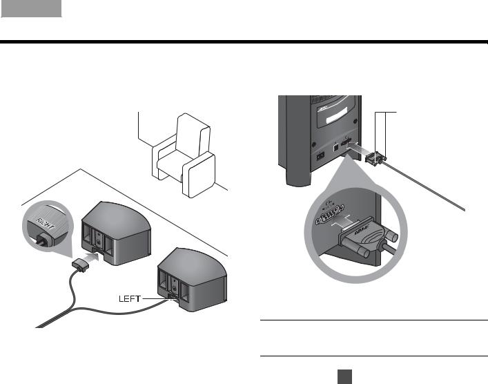
3.Insert each plug into the connector on the proper speaker.
The plug marked RIGHT goes into the speaker placed to the right of your TV.
4.Insert the remaining single plug into the connector labeled SPEAKERS on the back of the Acoustimass® module.
Fastener screws
5.Tighten each fastener screw by hand to secure the plug.
CAUTION: Do not plug the Acoustimass module into an AC power (mains) outlet until all other components are connected.
6. Continue with 3 on the next page.
9
Svenska |
Nederlands |
FrançaisItliano |
DeutschEspañol |
English |
|
|
|
|
|
SETUP
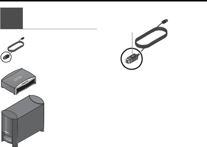
Connecting 3 the module to
the media center
What you need to use:
1.Notice the arrow on the top of the multi-pin plug at each end of the Acoustimass module cable.
Arrow
Acoustimass® module cable
Media center |
Make sure you can see the arrow on top before you |
2. |
|
|
insert either end of the cable. |
Acoustimass module
10
English |
DeutschEspañol |
FrançaisItliano |
Nederlands |
Svenska |
SETUP
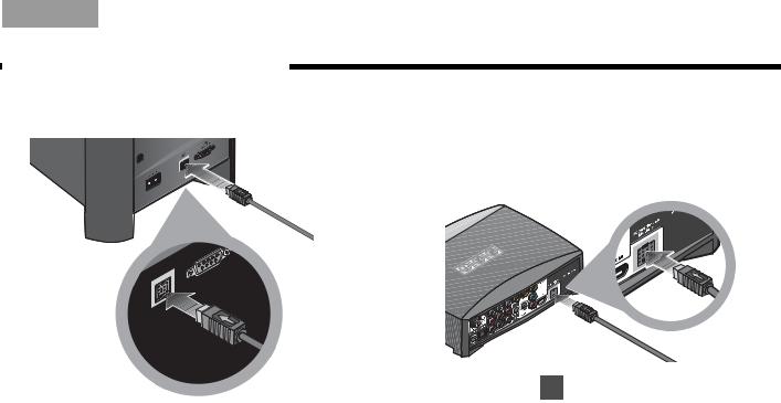
3.Insert this plug into the connector labeled  on the back of the Acoustimass® module.
4.On the other end of the cable, make sure you can see the arrow on top of the plug.
5.Insert this plug into the connector labeled Acoustimass Module on the back of the media center.
6. Continue with 4 on the next page.
Make sure the arrow on the plug faces up as you insert it.
11
Svenska |
Nederlands |
FrançaisItliano |
DeutschEspañol |
English |
|
|
|
|
|
SETUP
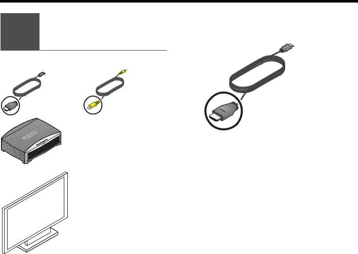
Connecting the 4 system video
to your TV
What you may need to use:
This connection allows you to see DVDs and other video from the 3•2•1® system on your TV.
1. Select the HDMI video cable.
HDMI |
OR |
Composite |
video cable |
|
video cable |
|
Media center |
|
Your TV
12
English |
DeutschEspañol |
FrançaisItliano |
Nederlands |
Svenska |
|
|
|
|
|
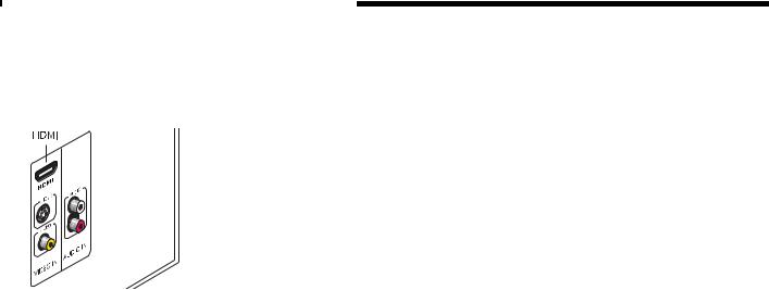
2.Check to see if your TV has an unused HDMI connector for VIDEO IN.
This may be located on the side or rear connector panel of the TV.
SETUP
3.Follow the directions that are appropriate for your TV:
TV with HDMI |
on page 14 |
|
|
or |
|
|
on page 15 |
TV without HDMI |
|
|
|
13

Svenska |
Nederlands |
FrançaisItliano |
DeutschEspañol |
English |
SETUP
TV with HDMI
1.Insert one end of the HDMI cable into the HDMI connector on your TV.
2.Insert the other end of this cable into the HDMI connector on the media center.
Make sure the Bose® logo shows as you insert the plug.
Bose
logo
Match the wide side of the plug to the wide side |
|
of the connector. |
Continue with 5 on page 17. |
3. |
Note: If you make this HDMI connection, you do not need the supplied yellow Composite video cable to make any connections.
DO NOT use either of the two ONLY PASS-THROUGH connectors on the back of the media center for video from a component.Neither S-Video nor Composite signals can pass through the HDMI cable to the TV.
14
English |
DeutschEspañol |
FrançaisItliano |
Nederlands |
|
|
|
|
|
|
|
|
|
|
|
|
|
|
|
|
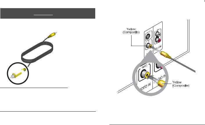
TV without HDMI
1.Notice the yellow plug at each end of the Composite video cable.
Yellow


 Yellow
Note: There may be other kinds of video connectors on your TV that offer higher resolution than Composite.
To use either S-Video or Component connectors, you need the appropriate cables. These cables are available at most electronics stores.
Svenska
SETUP
2.Plug the Composite video cable into the yellow VIDEO IN connector on your TV.
Note: If there is just one Composite Video In connector on your TV, it may be in use already for another video component. You can disconnect that component from the TV, and see “To use video pass through” on page 21.
15
Svenska |
Nederlands |
FrançaisItliano |
DeutschEspañol |
English |
|
|
|
|
|
SETUP
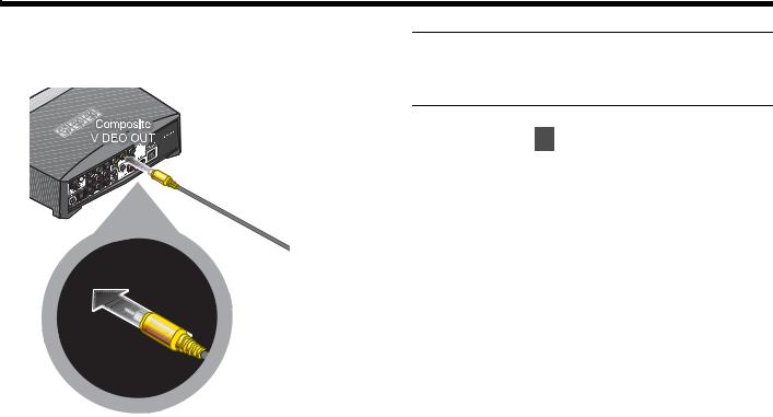
3.Insert the other end into the yellow Composite VIDEO OUT connector on the back of the media center.
Note: If you make this Composite connection, you can use the ONLY PASS-THROUGH connector on the media center for video from another component. See “To use
.a video pass through” on page 21 for further information.
4. Continue with 5 on the next page.
16
English |
DeutschEspañol |
FrançaisItliano |
Nederlands |
Svenska |
|
|
|
|
|
SETUP
Connecting 5 a cable box or
othercomponent
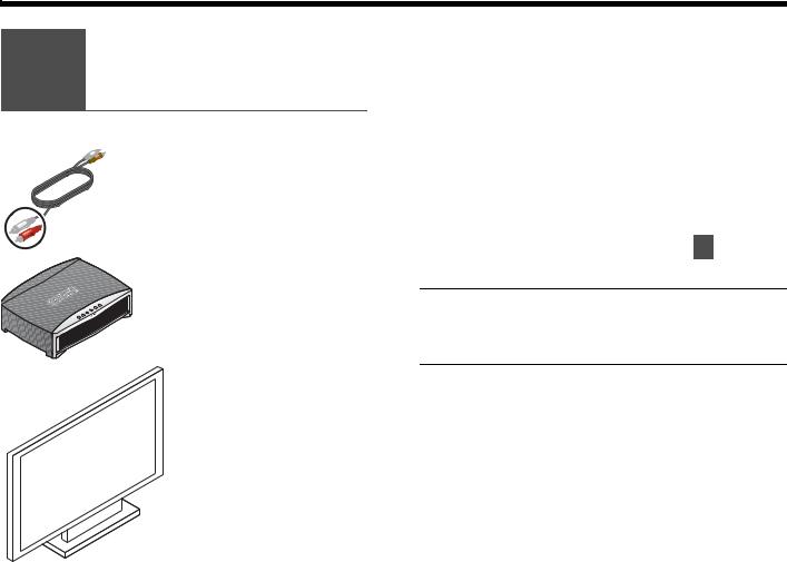
What you need to use:
Stereo audio cable
 Media center
Your cable box, satellite box, or other component
You can listen to another sound source — like a cable or satellite box — through the 3•2•1® speakers instead of your TV.
This requires an audio connection only. Leave the video from your component connected to your TV.
5.Select the audio cable that has red and white plugs at each end.
White plug
Red plug
17
Svenska |
Nederlands |
FrançaisItliano |
DeutschEspañol |
English |
|
|
|
|
|
SETUP
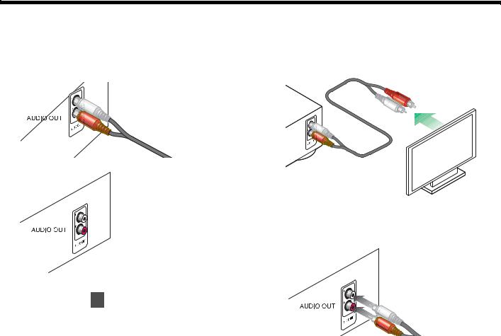
6.Check to see if your cable or satellite box has red and white AUDIO OUT connectors.
A red and white audio cable may (a) or may not (b) already be attached to these connectors.
a.
OR
b.
c. If there are no AUDIO OUT connectors at all,
continue with 6 on page 22.
3.To use the AUDIO OUT connectors, follow a or b as appropriate.
a. If an audio cable is already attached
Disconnect the cable from the TV only.
b. If an audio cable is not yet attached
Connect the cable to your cable or satellite box. Be sure to connect red to red and white to white.
18
English |
DeutschEspañol |
FrançaisItliano |
Nederlands |
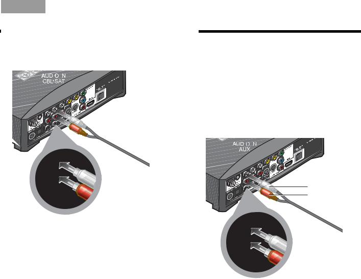
4.Insert the plugs at the other end of the audio cable into the CBL•SAT AUDIO IN connectors on the media center.
White plug
Red plug
Svenska
SETUP
To connect another component
In addition to your cable or satellite box, you can connect a second component, like a VCR. For this you need another audio cable with red and white plugs, available at most electronics stores.
1.Use this additional cable to connect to the AUDIO OUT on your component. Follow the method used in steps 1-3 on the previous pages.
2.Connect the other end of this cable to the AUDIO IN AUX on the 3•2•1® system media center.
White plug
Red plug
19
Svenska |
Nederlands |
FrançaisItliano |
DeutschEspañol |
English |
|
|
|
|
|
SETUP
To get digital audio from the component
For a component that is already connected to the media center, you can make a digital audio connection too.
For this higher quality audio, you need a digital audio cable that works with your component. Such cables are available at most electronics stores.
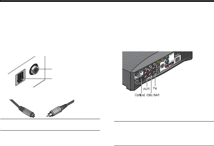
1.Identify the digital connector on your component as either an Optical or Coaxial connector.
Coaxial
Optical
2. Be sure to use the right cable for this connector.
Optical OR Coaxial
3.Connect one end of your digital cable to the digital AUDIO OUT connector on your component.
Be sure to keep the red and white audio cable connected. This allows you to hear the audio if the program audio is not digital or the digital signal is interrupted.
4.Locate the appropriate digital AUDIO IN connector, labeled D, on the system media center.
You can make:
•up to 3 coaxial connections
•up to 2 coaxial and one optical connection
Note: If your component has an Optical and a Coaxial connector, use either one but not both.
Note: The media center Optical connector is factory set to work with a cable or satellite box. If your Optical component is neither of those, you need to select your component in an on-screen System menu. See “Getting digital audio from a source” on page 45.
20
English |
DeutschEspañol |
FrançaisItliano |
Nederlands |
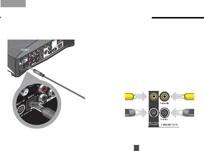
5.Plug the other end of your digital cable into the appropriate AUDIO IN connector on the media center.
The example here shows an Optical digital connection only.
Svenska
SETUP
To use video pass through
This calls for another composite cable or two S-Video cables, which are available at most electronics stores.
You can make a pass through connection if:
•You have a Composite or S-Video connection between the TV and the media center (not HDMI or Component).
AND:
•You want to connect another video component through the media center to the TV.
Be sure to use one matched pair as shown here:
Video in from |
Video out |
your component |
to your TV |
DO NOT use either of the two ONLY PASS-THROUGH connectors (on the left) if you have made an HDMI or Component connection VIDEO OUT TO TV.
Continue with 6 on the next page.
21
Svenska |
Nederlands |
FrançaisItliano |
DeutschEspañol |
English |
|
|
|
|
|
SETUP
Connecting audio 6 from your TV as
an option
What you need to use:
Audio cable
Media center
For some setups, in order to hear your TV sound from your 3•2•1® speakers, you need to make this connection.
If:
•Your cable box does not provide red and white AUDIO OUT connectors.
•You watch TV programs without using a cable or satellite box.
•You connect a video camera or game console to your TV.
If none of the above apply, continue with 7 on page 25.
Note: If you have already connected the audio
cable provided with the system, you need another cable for this connection. These cables are available at most electronics stores.
Your TV
22
|
English |
DeutschEspañol |
FrançaisItliano |
Nederlands |
|
|
|
|
|
|
|
|
|
|
|
|
|
|
|
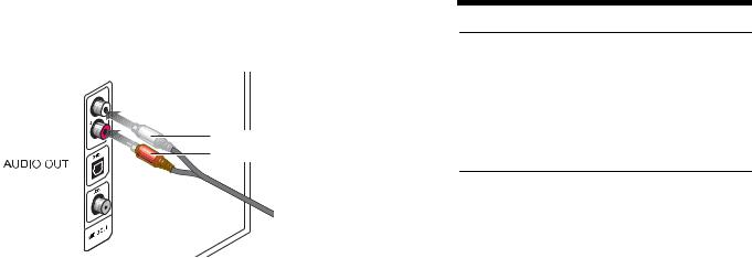
1.Insert the red and white plugs at one end of the cable into the AUDIO OUT connectors on the TV.
White plug
Red plug
Be sure to match red to red and white to white.
Note: In addition to this connection, you can make a digital AUDIO OUT connection from the TV to the media center. For more information, review “To get digital audio from the component” on page 20.
Svenska
SETUP
Note: If your TV does not provide AUDIO OUT connectors, you cannot connect the TV audio to the 3•2•1® system. Continue to use your TV speakers for TV program audio.
The audio from other components that are connected to the 3•2•1 media center will play through the 3•2•1 speakers.
23
Svenska |
Nederlands |
FrançaisItliano |
DeutschEspañol |
English |
SETUP
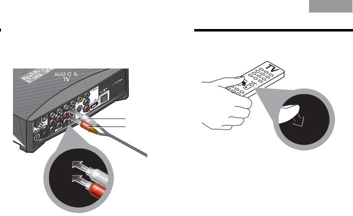
2.Insert the red and white plugs at the other end of this cable into the AUDIO IN TV connectors on the media center.
3.Use your TV remote control to turn the TV speakers down to minimum volume.
White plug
Red plug
This prevents the echo effect of audio playing through both the TV speakers and your 3•2•1® system speakers.
Be sure to match red to red and white to white.
24
English |
DeutschEspañol |
FrançaisItliano |
Nederlands |
Svenska |
|
|
|
|
|
SETUP
Installing
7 the FM and AM
radio antennas
What you need to use:
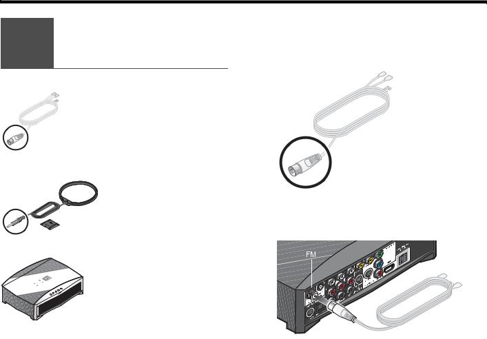
FM antenna
AM antenna and stand
 Media center
For radio reception of broadcast radio programs, you need to use the supplied antennas.
For FM:
1. Select the FM antenna.
2.Insert the antenna plug into the FM antenna connector.
25
Svenska |
Nederlands |
FrançaisItliano |
DeutschEspañol |
English |
SETUP |
|
|
|
|
|
|
|
|
|
|
|
|
|
|
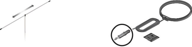
3. Straighten the antenna cable and spread the two |
For AM: |
|
|
|
ends far apart. |
1. Select the AM antenna and stand. |
|
||
You may need to raise the ends and adjust the position to get clear reception.
26
 Loading...