


The Bose® 131TM Marine Speaker System
Owner’s Guide
October 30, 2001
AM188201_02_V.pdf

Safety, Warranty, and Technical Information
Please read this owner’s guide
The Bose® 131TM marine speaker system is engineered to provide sound quality far beyond other marine speaker systems. This guide helps you install and use your speaker system properly. Please read the installation section completely before cutting any holes. It is important to understand the reasons for choosing one mounting hole size over the other.
Warranty period
Bose 131 marine speakers are covered by a limited 3-year transferable warranty. Details of the coverage are provided on the warranty card that came with your speakers. Please fill out the information section on your card. Then detach the card, and mail it to Bose Corporation.
Technical information
Features
•Polymer fiber driver cone
•Dual-port polypropylene enclosure
•Syncom II® computer quality control
Speaker driver complement
•One 41⁄2" (11.4 cm) full range environmental driver per enclosure
Compatibility/Impedance
•Maximum continuous power per I.E.C.: 40W
•Compatible with receivers or amplifiers 10 - 80 watts per channel
•Impedance 4 - 8 ohms
Finish
• Grille: Arctic White
Size/Dimensions
•Weight, unpacked: 9 lb (4 kg)
•12"L x 31⁄2"D (30 cm x 8.9 cm)
•Cut out Diameter:
•53⁄8" (13.7 cm) with access to rear of mounting surface
•71⁄8" (18 cm) without access to rear of mounting surface
•Grille Diameter: 8" (21 cm)
•Mounting Depth: 31⁄2" (8.9 cm)
•Mounting Wall Thickness:
.75" (1.9 cm maximum) rear mounting
.50"(1.2 cm maximum) front mounting
For your records…
Serial numbers are located on the label of each 131 marine speaker.
Serial numbers: _____________________ and _____________________________________
Dealer name: __________________________________________________________________
Dealer phone: _______________________ Purchase date: ___________________________
We suggest you keep your sales slip and warranty card together with this owner’s guide.
2 |
October 30, 2001 |
AM188201_02_V.pdf |

Contents/Records
Where to find…
Setting up |
|
Unpack the carton ........................................................................................................ |
4 |
Tools required ............................................................................................................... |
4 |
Select the locations for your speakers ......................................................................... |
5 |
Installing Your Speakers |
|
Test the speakers ......................................................................................................... |
6 |
Mounting the speakers ................................................................................................. |
6 |
Installation from the rear of the bulkhead ..................................................................... |
7 |
Installation from the front of the bulkhead .................................................................. |
11 |
Maintaining Your Speakers |
|
Cleaning the speakers ................................................................................................ |
16 |
Troubleshooting .......................................................................................................... |
16 |
Bose® Corporation .................................................................................... |
inside back cover |
DECLARATION OF CONFORMITY
We, the offerer:
Bose® Corporation, The Mountain,
Framingham, MA 01701-9168 USA
acknowledge our sole responsibility, that the product:
Kind of equipment: Loudspeaker
Type designation: 131™ marine speaker system
in accordance with EMC Directive 89/336/EEC and Article 10(1) of the Directive,
is in compliance with the following norm(s) or document(s):
Technical regulations: EN50081-1, EN50082-1
Accredited by Bose Corporation
23 January 1997
Bose B.V. |
|
Nijverheidstraat 8, 1135 GE Edam |
General Manager, Bose Europe |
The Netherlands |
Manufacturer’s authorized EU representative |
AM188201_02_V.pdf |
October 30, 2001 |
3 |

Setting Up
Unpack the carton
Carefully unpack your speakers and save all packing materials for possible future use. Do not attempt to use your speaker system if any part of it appears damaged. Notify Bose® Corporation or your authorized Bose dealer immediately. Check that your system contains the parts identified in Figure 1. For shipping, the mounting flange is packed inside its speaker grille. Separate these components before installation.
Notes: Please remove the perforated drilling and cutting template from the inner carton containing the grille and mounting flange. Also remove the perforated speaker cone shields from the inner cartons containing the enclosures. You will need the template and shields during installation.
Now is a good time to record each speaker serial number on page 2 of this guide and on your warranty card.
CAUTION: The 131TM marine speakers are not intended to be installed in automobiles.
Figure 1
Packaging Contents:
• Two 131 marine speaker enclosures
• Two mounting flanges
• Two speaker grilles
• One Owner’s Guide
• One template for positioning, cutting, and drilling holes
• Two speaker cone shields
• Mounting hardware:
• 30 screws (6 extra)
• 10 wire nut connectors (2 extra)
• Two 20 foot speaker cables, 18-gauge
Tools required
You will need the following tools to complete this installation:
•Phillips-head screwdriver.
•An appropriate cutting tool for the surface to be cut. For installation in fiberglass or wood, we recommend a sabre saw. Use a short blade, and have some extra blades available. A hole saw may also be used. Large diameter hole saws are available and they allow you to make circular cuts on a flat surface.
•Drill with the following bits:
- For drilling the screw holes a 3⁄32 inch (.24 cm) bit is preferred, but you could also use a
1⁄8 (.32 cm) inch bit.
- For drilling the starter hole, use a 5⁄16 inch (.8 cm) bit.
•Center punch or awl.
•Half-round file or rasp.
•Eye and ear protection; dust mask.
CAUTION: Failure to follow these instructions voids all warranties on your speakers. If you are unsure of your ability to complete this process, consult a professional installer. Please read this owner’s guide completely before beginning installation.
4 |
October 30, 2001 |
AM188201_02_V.pdf |
Setting Up
Select the locations for your speakers
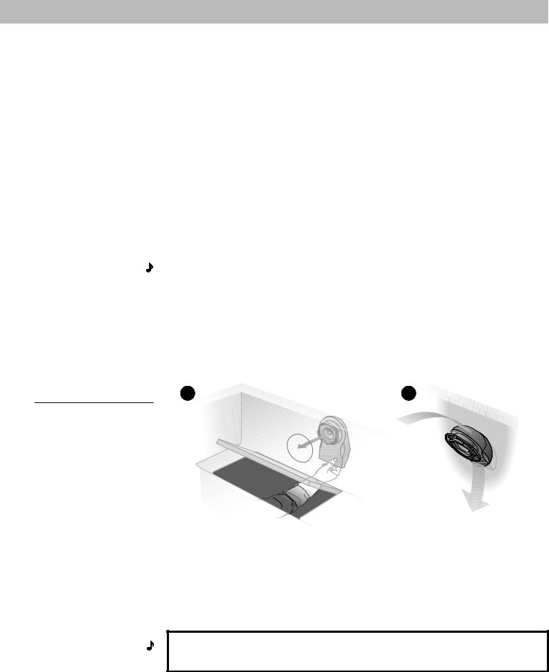
In selecting locations for your speakers, understand that there are two possible mounting options. It is easiest to mount the speakers from behind the mounting surface. However, if you cannot reach behind the mounting surface, you may cut a larger hole that allows you to insert the speaker enclosure from the front of the mounting surface. See Figure 2. With this in mind, find a location that:
•Allows sufficient room to snap on the grille. Use the template to be sure there is enough area around the holes you will cut in the bulkhead.
•Allows sufficient room for the speaker enclosure behind the bulkhead. During installation, the enclosure requires 41⁄2 inches (11 cm) of mounting depth. However, once installed the enclosure requires only 31⁄2 inches (9 cm) of mounting depth and 12 inches (31 cm) of extension. The enclosure may be rotated in a complete circle, but attaches to the mounting flange in only one position.
•Accommodates the speaker wire provided. Lay out lengths of wire that comfortably reach from the receiver to each speaker. Be sure the wires are secure and protected from being pinched, pulled, or damaged in any way.
•Is not close enough to adversely affect any compass.
Note: The magnets in the speakers will affect a boat compass. Avoid mounting the speakers closer than three feet from the compass. If necessary, a marine installer can help correct any deviation.
Figure 2 |
A |
Selecting the right locations
A.Mount from the rear if you can insert the speaker enclosure behind the bulkhead mounting surface.
B.Mount from the front if you cannot reach behind the mounting surface. If you are uncertain about the depth and clearance behind your mounting surface, consult your boat manufacturer or dealer.
B |
Note: Before going any further with your assembly, choose one of the methods described in Figure 2 above. The instructions for A begin on page 7; B on page 11.
AM188201_02_V.pdf |
October 30, 2001 |
5 |
Installing Your Speakers
Test the speakers
It is a good idea to test your system before installation. With the power turned off, connect the receiver to the speakers.
The provided speaker cord consists of two insulated wires; one is marked or ribbed, and is always positive (+). The plain wire is always negative (–). The wires correspond to the red (+) and black (–) terminals on the back of the speaker, receiver, or amplifier. Place the stripped end of the positive (+) right channel receiver wire together with the stripped end of the positive (+) right speaker wire. Then place the stripped end of the negative right channel receiver wire together with the stripped end of the negative right speaker wire. Repeat this procedure for the left speaker.
Be sure to connect each wire to the proper terminal (positive to positive, negative to negative). For this test, just twist the wire ends together. You will use the supplied wire nuts for the permanent connections.
When you are satisfied that everything works, disconnect the speakers and continue with the installation.
Mounting the speakers
CAUTION: Be sure to mount your 131TM marine speakers on a bulkhead only. Do not cut holes in the hull. We recommend you consult a marine installer before drilling or cutting any holes. Choose a safe spot for drilling. Do not mount the speakers on surfaces with concealed hazards, such as electrical conduits or plumbing.
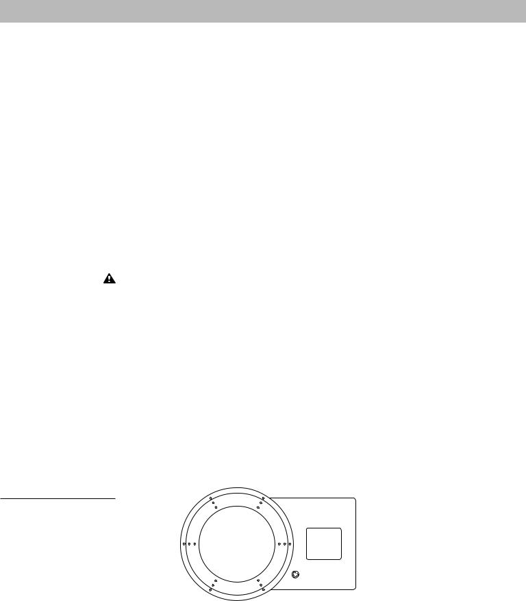
The cutting and drilling template
Locate the cutting and drilling template. It is perforated into the inner carton that contained your grilles and mounting flanges. The template has four functions.
1.It helps you position the speaker enclosure by showing how much room to provide for the extension of the enclosure behind the bulkhead.
2.It shows you how much room to allow for the snap on grille.
3.It assists you in cutting the appropriate hole size in the bulkhead wall.
4.It helps you drill the mounting screw holes in the bulkhead.
The template has two punch-out hole diameters. Use the smaller size for installation from behind the bulkhead. Use the larger for installation from the front. See Figures 2 & 3.
Figure 3
The template
6 |
October 30, 2001 |
AM188201_02_V.pdf |
 Loading...