


Bosch WTZ1500C, WTZ1500, WTZ1500S, WTZ 1295P, WTZ1500P User Manual
...
Bosch Nexxt™ Laundry Pedestals
Models / Modèles / Modelos: WTZ 1295, WTZ 1295S
WTZ 1295P, WTZ 1295C
en |
Operating, Care and Installation Instructions |
fr |
Socle: Notice d’utilsation, de maintenance et d’installation |
es |
Pedestal: Operacíon, cuidado y instrucciones para la instalación |
|
|
|
|
Important Safety Information
Please read and follow these
Installation Instructions along with all other information enclosed with the pedestal.
Definitions
dWARNING
WARNING - This indicates that death or serious injuries may occur as a result of non^observance of this warning.
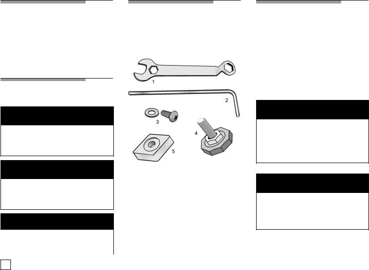
Tools and Parts
Confirm receipt of |
the following parts |
and tools in the |
pedestal drawer: |
dCAUTION
CAUTIONThis indicates that minor or moderate injury may occur as a result of non^observance of this warning.
NOTICE
Figure 1
1. 17 mm open end wrench
2. 6 mm Allen (Hex) wrench
3. (4) Socket Head Cap Screws and
(4)Flat Washers
4.(4) Height Adjustable Feet
NOTICE - This indicates that |
of5. |
(4) Spacers |
damage may occur as a result |
||
non^observance of this warning. |
6. |
Warranty Card(not pictured) |
|
|
|
Before |
You |
Start |
||
|
|
|
|
|
i |
Important: |
If your |
appliance is |
|
|
already installed, it MUST be |
|||
|
uninstalled |
before |
continuing. |
|
If you need to uninstall |
your appliance, |
|||
refer to the•Operating, Care and |
||||
Installation |
Instructions" provided |
|||
with your appliance for tools and |
||||
information |
required. |
|
||
dCAUTION
Excessive Weight Hazard
Use two or more people to move and uninstall the appliance.
Failure to do so can result in injury.
dCAUTION
Do not lift the appliance by the door or door opening.
Keep the door closed at all times during the pedestal installation.
iThis symbol is used to draw the
user's attention to important matters.
2
Preparing |
Your |
|
Appliance |
|
|
Existing Appliance -If you are |
||
installing the pedestal |
on |
an appliance |
that has already been in |
use, begin with |
|
the •Preparing Your |
Existing |
|
Appliance" section immediately |
||
below. |
|
|
New Appliance If-you |
are installing |
|
the pedestal on a new washer or dryer, proceed to the•Preparing Your New Appliance" section on the page following.
Preparing |
Your |
|
|
|
|||
Existing |
Appliance |
|
|
||||
1. Pull the appliance away from the |
|
||||||
wall |
so it |
can be positioned on |
its |
||||
left |
side. |
|
|
|
|
|
|
Step |
2 below |
applies |
to |
washers |
|||
For |
dryers |
go |
directly |
to |
step |
3 |
|
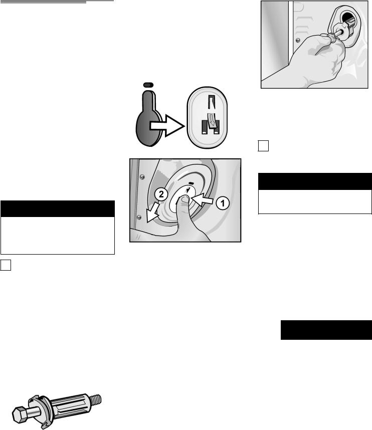
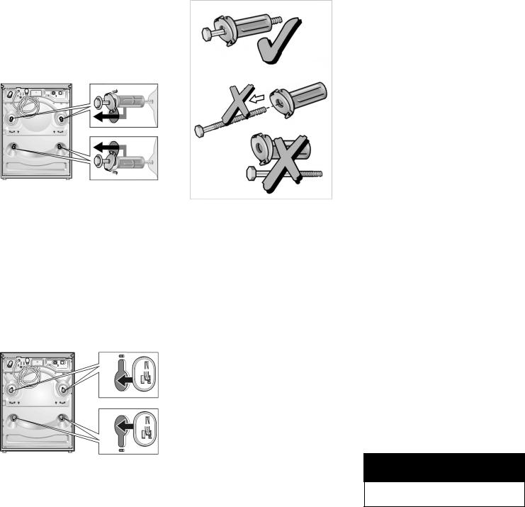
q Remove the four transportation bolt hole covers on the back of the washer. (1) Push the tab inward with your thumb while
(2) sliding the cover in the direction of the two vertical slots in the plastic cover (see
Figure 3).
NOTICE
Make sure the washer transportation bolts are reinstalled prior to pedestal installation to prevent potential damage to the washer drum.
iYour washer was originally
shipped with four transportation bolts installed to protect the drum during transit. The washer installation instructions required these bolts to be removed during the original setup. The transportation bolts must now be reinstalled prior to pedestal installation.
2. To reinstall the transportation bolts:
q Locate the four transportation bolt assemblies originally shipped with your washer (see
Figure 2).
Figure 2
|
|
|
|
|
|
|
|
|
3. |
Protect |
the |
floor and the side of th |
|||||||||||||
|
|
|
|
|
|
|
|
|
|
|
|
appliance by laying a sufficiently |
|||||||||||||
|
|
|
|
|
|
|
|
|
|
|
|
large |
|
piece |
of |
cardboard (such |
as |
||||||||
|
|
|
|
|
|
|
|
|
|
|
|
the pedestal carton) or other |
|
||||||||||||
|
|
Figure |
3 |
|
|
|
|
|
|
|
suitable |
protective |
covering |
flat |
on |
||||||||||
q Insert the bolt assemblies. |
|
|
|
the |
|
floor |
to |
the |
left |
of |
the |
unit. |
|||||||||||||
|
|
|
|
|
|
|
|
|
|
|
|
|
|
|
|
|
|||||||||
Start with the lower left and |
|
|
|
Support |
the |
appliance |
|
|
|
|
|||||||||||||||
install all four assemblies going |
|
approximately 1 1/2" to 2" off the |
|||||||||||||||||||||||
counterclockwise. |
Align |
each |
|
|
|
floor |
|
(seeFigure |
5). |
|
|
|
|
|
|||||||||||
one into the hole until the |
|
|
|
|
|
|
|
|
|
|
|
|
|
|
|
|
|
||||||||
plastic bushing is all the way |
|
Helpful |
Hint: |
|
Rolled |
up towels |
can |
||||||||||||||||||
inside the back panel of the |
|
|
|
be |
used |
as |
support. |
|
|
|
|
|
|||||||||||||
washer |
and |
the |
rectangular |
|
|
|
|
|
|
|
|
|
|
|
|
|
|
|
|
|
|||||
collar |
is |
oriented |
to |
fit the slot. |
|
|
|
|
|
|
|
|
|
|
|
|
|
|
|
|
|||||
|
d |
|
|
CAUTION |
|
|
|
|
|||||||||||||||||
This |
aligns the |
bolt |
assembly |
so |
|
|
|
|
|
|
|
||||||||||||||
the |
bolt |
will |
thread |
correctly |
into |
|
|
|
|
|
|
|
|
|
|
|
|
|
|
|
|
||||
the |
drum. |
Slide |
the bolt |
|
|
When lifting or lowering the |
|
|
|||||||||||||||||
assembly in the direction of the |
|
appliance onto its side, avoid |
|
|
|||||||||||||||||||||
slotted |
area. |
|
|
|
|
|
|
|
sliding |
|
it |
against |
the |
floor |
as |
|
this |
||||||||
|
|
|
|
|
|
|
|
|
|
|
may |
result |
in injury |
or |
damage. |
|
|||||||||
q When |
installing |
the |
first |
bolt |
|
|
|
|
|
|
|
|
|
|
|
|
|
|
|
|
|
||||
|
|
|
|
|
|
|
|
|
|
|
|
|
|
|
|
|
|||||||||
assembly, it |
is |
necessary |
to |
4. |
Lay |
|
the appliance onLEFTits |
side |
|
||||||||||||||||
push against the drum with the |
|
(see Figure |
6). |
|
|
|
|
|
|
|
|||||||||||||||
assembly to |
allow |
it |
to |
slide |
into |
|
Note |
for |
Washers:Slight |
water |
|
||||||||||||||
place. |
|
|
|
|
|
|
|
|
|
|
|
||||||||||||||
|
|
|
|
|
|
|
|
|
|
spillage may be noticed due to |
|||||||||||||||
|
|
|
|
|
|
|
|
|
|
|
|
||||||||||||||
|
|
|
|
|
|
|
|
|
|
|
|
laying |
washer |
on |
its |
side. |
|
|
|
||||||
5.Go to the•Installing the
Pedestal" section of this manual.
3
Preparing |
Your |
New |
4. |
Lay the appliance |
onLEFTits side |
||||
|
(see Figure 6). |
|
|||||||
Appliance |
|
|
|
|
|
|
|
||
|
|
|
|
|
|
Note for Washers:Slight water |
|||
|
|
|
|
|
|
|
|
||
1. Position the original packaged |
|
spillage may be noticed due to |
|||||||
appliance close to the final location. |
laying washer on |
its side. |
|||||||
Using a utility knife, cut the two |
|
|
|
||||||
packaging straps. |
|
|
|
|
|
|
|
||
|
|
|
|
|
|
|
|
|
|
|
NOTICE |
|
|
|
|
|
|
|
|
|
|
|
|
|
|
|
|
||
If installing the pedestal to a new |
|
|
|
||||||
washer, do not |
remove |
the |
|
|
|
||||
washer transportation |
boltsprior |
|
|
|
|||||
to installing the |
pedestal. |
|
|
|
|||||
|
|
|
|
|
|
|
|
|
|
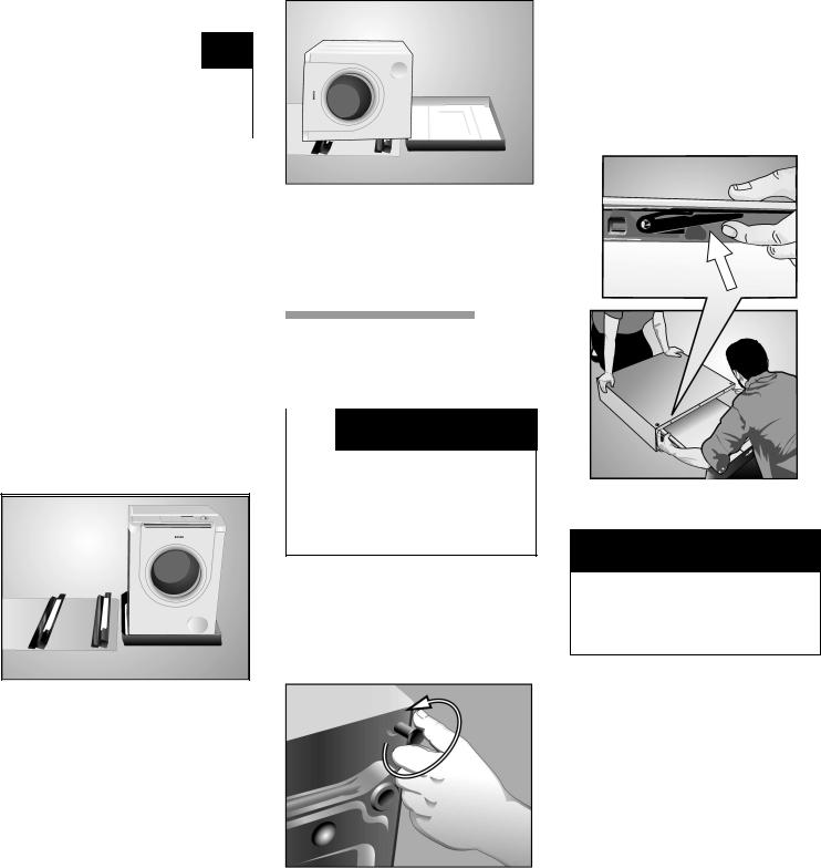
2.Remove the protective film, four corner supports, and two foam packaging pieces.
3. Protect the floor and the side of |
the |
|
Figure 6 |
|||||||
appliance by laying a sufficiently |
|
|
5. Remove the bottom of the |
|||||||
large piece of cardboard (such |
as |
|
|
packaging. |
|
|
||||
the pedestal carton) or other |
|
|
|
6. Go to•Installing the Pedestal" |
||||||
suitable protective covering flat |
on |
|
|
|||||||
the floor to the left of the unit. |
|
|
section |
of |
this manual. |
|||||
Support the appliance |
|
|
|
|
|
|
|
|
||
|
|
|
|
|
|
|
|
|||
approximately 1 1/2" to 2" off the |
|
|
Installing |
the |
||||||
floor. |
|
|
|
|
|
|||||
Helpful Hint: Place the two corner Pedestal |
|
|||||||||
supports |
from your appliance |
|
|
|
|
|
|
|
|
|
packaging |
(seeFigure |
5). |
|
|
|
d |
|
CAUTION |
||
If corner supports are not available, |
|
|||||||||
|
|
|
|
|
|
|||||
items such as rolled |
up towels |
can Do not |
place |
fingers near the |
||||||
be used. |
|
|
|
|
|
bottom |
of |
the |
pedestal while |
|
moving the drawer.
Doing so can result in a cut or pinch injury.
Figure 5
the floor under the pedestal.
Remove the drawer from the pedestal by depressing the drawer release levers located in the drawer slide rails. Set the drawer aside.
Helpful hint:It is recommended to have an assistant hold the pedestal
housing |
during |
drawer |
removal. |
Push up |
on the |
drawer |
release |
lever on |
theleft side anddown on |
||
the drawer release lever on the right side while removing the drawer (seeFigure 8).
Figure 8
d CAUTION
4
|
|
|
|
|
|
|
Use |
the |
wrench HANDto |
|
|
|
|
|
|
|
|
|
|
|
|
|
|
|
|
|
|
|
|
|
|
|
|
||||||
|
|
|
|
|
|
|
|
|
|
|
|
|
|
|
d |
|
|
CAUTION |
|
|
|
|
|||||||||||||||||
|
|
|
|
|
|
|
TIGHTEN all screws (seeFigure |
|
|
|
|
|
|
|
|
|
|
||||||||||||||||||||||
|
|
|
|
|
|
|
10). |
|
|
|
|
|
|
|
|
|
|
|
|
|
|
|
|
|
|
|
|
|
|
|
|
|
|
|
|
|
|
|
|
|
|
|
|
|
|
|
Helpful |
|
hint: Do |
not tighten |
any |
|
When |
lifting |
the |
appliance, |
be |
|
|||||||||||||||||||||
|
|
|
|
|
|
|
|
|
careful |
not |
to |
allow |
it |
to |
|
slide |
|
||||||||||||||||||||||
|
|
|
|
|
|
|
screws |
completely |
until |
|
all |
are |
|
|
against |
the |
floor. |
|
|
|
|
|
|
||||||||||||||||
|
|
|
|
|
|
|
started |
into their |
threads. |
|
|
|
|
|
|
|
|
|
|
|
|
|
|
|
|
|
|
|
|
|
|||||||||
|
|
|
|
|
|
|
After all |
|
screws |
are hand |
tight, |
use |
|
If |
|
the |
appliance |
slides, |
it |
|
may |
|
|||||||||||||||||
|
|
|
|
|
|
|
the wrench to tighten an |
additional |
|
cause |
injury |
or |
damage. |
|
|
|
|||||||||||||||||||||||
|
|
|
|
|
|
|
1/3 |
to |
1/2 turn |
Figure(see |
11). |
|
|
|
|
|
|
|
|
|
|
|
|
|
|
|
|
|
|
|
|
||||||||
|
|
|
|
|
|
|
|
|
|
6. |
Lift |
|
the appliance and pedestal |
|
|||||||||||||||||||||||||
|
|
|
|
|
|
|
Note: Tightening |
torque |
|
for |
the |
|
|
|
|||||||||||||||||||||||||
|
|
|
|
|
|
|
|
|
|
|
assembly back |
to |
an upright |
|
|||||||||||||||||||||||||
|
|
|
|
|
|
|
pedestal |
screws |
is |
|
a |
minimum |
of |
|
|
|
|||||||||||||||||||||||
|
|
|
|
|
|
|
|
|
|
position |
(use |
of |
an |
|
assistant is |
|
|||||||||||||||||||||||
|
Figure |
|
9 |
|
|
10 |
|
ft^lb |
|
(14 N-m) |
|
to |
13 ft-lb |
(18 |
|
|
|
|
|||||||||||||||||||||
|
|
|
|
|
|
|
|
|
required) |
(seeFigure |
|
13). |
|
|
|
|
|||||||||||||||||||||||
4. Using the |
6 mm |
|
Allen (Hex) |
|
N-m). |
|
|
|
|
|
|
|
|
|
|
|
|
|
|
|
|
|
|
|
|
||||||||||||||
|
|
|
|
|
|
|
|
|
|
|
|
|
|
|
|
|
|
|
|
|
|
|
|
|
|
|
|
|
|
|
|
||||||||
|
|
|
|
|
|
|
|
|
|
|
|
|
|
|
|
|
|
|
|
|
|
|
|
|
|
|
|
|
|
|
|
|
|
|
|||||
wrench, install the socket head cap |
|
|
|
|
|
|
|
|
|
|
|
|
|
|
|
|
|
|
|
|
|
|
|
|
|
|
|
|
|
|
|
|
|||||||
|
|
|
|
|
|
|
|
|
|
|
|
|
|
|
|
d |
|
|
CAUTION |
|
|
|
|
||||||||||||||||
screws and flat washers (see |
|
|
|
|
|
|
|
|
|
|
|
|
|
|
|
|
|
|
|
|
|
|
|
||||||||||||||||
Figure |
10). |
|
|
|
|
|
|
|
|
|
|
|
|
|
|
|
|
|
|
|
|
|
|
|
|
|
|
|
|
|
|
|
|
|
|
|
|
|
|
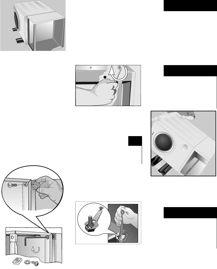
Insert the square spacer between |
|
|
|
|
|
|
|
|
|
|
|
|
|
|
|
|
|
Avoid holding the appliance by |
|||||||||||||||||||||
|
|
|
|
|
|
|
|
|
|
|
|
|
|
|
|
|
the |
pedestal when |
lifting |
it. |
|
||||||||||||||||||
the pedestal housing and the |
|
|
|
|
|
|
|
|
|
|
|
|
|
|
|
|
|
|
|
|
|
|
|
|
|
|
|
|
|
|
|
|
|
||||||
appliance housing. |
Holding |
the |
|
|
|
|
|
|
|
|
|
|
|
|
|
|
|
|
|
To |
avoid |
damaging |
|
the |
pedestal |
||||||||||||||
spacer |
in |
place, |
insert |
the bolt so |
|
|
|
|
|
|
|
|
|
|
|
|
|
|
|
|
|
|
|||||||||||||||||
|
|
|
|
|
|
|
|
|
|
|
|
|
|
|
|
|
do |
not |
use |
a |
dolly |
to |
lift |
or |
move |
||||||||||||||
passes |
through |
the flat |
washer, |
|
|
|
|
|
|
|
|
|
|
|
|
|
|
|
|
|
|||||||||||||||||||
|
|
|
|
|
|
|
|
|
|
|
|
|
|
|
|
|
the |
appliance |
once |
|
the |
pedestal |
|||||||||||||||||
pedestal housing, then the spacer, |
|
|
|
|
|
|
|
|
|
|
|
|
|
|
|
|
|
|
|||||||||||||||||||||
|
|
|
|
|
|
|
|
|
|
|
|
|
|
|
|
|
is |
|
installed. |
|
|
|
|
|
|
|
|
|
|||||||||||
and into the protruding threaded |
|
|
|
|
|
|
|
|
|
|
|
|
|
|
|
|
|
|
|
|
|
|
|
|
|
|
|
||||||||||||
bushing |
in |
the |
appliance base. |
|
|
|
|
Figure |
11 |
|
|
|
|
|
|
|
|
|
|
|
|
|
|
|
|
|
|
|
|
|
|
|
|
||||||
Repeat |
for |
all four bolts. |
|
|
|
|
|
|
|
|
|
|
|
|
|
|
|
|
|
|
|
|
|
|
|
|
|
|
|
|
|
||||||||
|
5. Install the four new feet that are |
|
|
|
|
|
|
|
|
|
|
|
|
|
|
|
|
|
|||||||||||||||||||||
|
|
|
|
|
|
|
|
|
|
|
|
|
|
|
|
|
|
|
|
|
|
|
|
||||||||||||||||
Make sure |
the |
webbed |
side |
of |
included |
|
with |
the |
pedestal. |
|
Screw |
|
|
|
|
|
|
|
|
|
|
|
|
|
|
|
|
|
|||||||||||
each spacer is down toward |
the |
the |
feet |
|
into |
the |
threaded |
corner |
|
|
|
|
|
|
|
|
|
|
|
|
|
|
|
|
|
||||||||||||||
base of |
the pedestal. |
The |
spacer |
holes in |
|
the |
base |
|
of |
the |
pedestal. |
|
|
|
|
|
|
|
|
|
|
|
|
|
|
|
|
|
|||||||||||
should fit up against the appliance |
|
|
|
|
|
|
|
|
|
|
|
|
|
|
|
|
|
|
|
|
|
|
|
|
|
|
|
|
|
|
|
|
|
||||||
housing. Align the outer edges of |
|
|
|
NOTICE |
|
|
|
|
|
|
|
|
|
|
|
|
|
|
|
|
|
|
|
|
|
|
|
|
|||||||||||
the spacer with the appliance and |
|
|
|
|
|
|
|
|
|
|
|
|
|
|
|
|
|
|
|
|
|
|
|
|
|
|
|
||||||||||||
pedestal |
housings. |
Loosely |
thread |
|
|
|
|
|
|
|
|
|
|
|
|
|
|
|
|
|
|
|
|
|
|
|
|
|
|
|
|
|
|
|
|
|
|||
Use |
|
only |
the |
feet |
supplied |
|
|
|
|
|
|
|
|
|
|
|
|
|
|
|
|
|
|
|
|||||||||||||||
all four |
bolts with the |
washers and |
|
|
|
|
|
|
|
|
|
|
|
|
|
|
|
|
|
|
|
|
|||||||||||||||||
spacers |
in |
place |
before |
tightening |
with |
|
the |
pedestal. |
Do not use |
|
|
|
|
|
|
|
|
|
|
|
|
|
|
|
|
|
|||||||||||||
the |
feet |
that |
originally |
|
came |
with |
|
|
|
|
|
|
|
|
|
|
|
|
|
|
|
|
|
||||||||||||||||
any of |
the bolts |
completely. |
|
|
|
|
|
|
|
|
|
|
|
|
|
|
|
|
|
|
|
||||||||||||||||||
|
the |
appliance. |
|
|
|
|
|
|
|
|
|
|
|
|
|
|
|
|
|
|
|
|
|
|
|
|
|
|
|
|
|||||||||
|
|
|
|
|
|
|
|
|
|
|
|
|
|
|
|
|
|
|
|
|
|
|
|
|
|
|
|
|
|
|
|
|
|
|
|||||
|
|
|
|
|
|
|
|
|
|
|
|
|
|
|
|
|
|
|
|
|
|
|
|
|
|
|
|
||||||||||||
|
|
|
|
|
|
|
Using the supplied |
17 mm |
open |
|
|
|
|
|
|
|
|
|
|
|
|
|
|
|
|
|
|||||||||||||
|
|
|
|
|
|
|
end wrench, tighten only the two |
|
|
|
|
|
|
|
|
|
|
|
|
|
|
|
|
|
|||||||||||||||
|
|
|
|
|
|
|
rear feet locknuts against the |
|
|
|
|
|
|
|
|
|
|
|
|
|
|
|
|
|
|
||||||||||||||
|
|
|
|
|
|
|
pedestal |
|
housing |
(seeFigure 12). |
|
|
|
|
|
|
|
|
Figure |
13 |
|
|
|
|
|
||||||||||||||
|
|
|
|
|
|
|
The front two feet should be handStep 7 below applies to washers. |
||||||||||||||||||||||||||||||||
|
|
|
|
|
|
|
tightened |
only, so |
|
the |
|
appliance |
For |
|
dryers go directly to |
step 8. |
|||||||||||||||||||||||
|
|
|
|
|
|
|
can |
be |
|
leveled |
later. |
|
|
|
|
|
|
|
|
||||||||||||||||||||
|
|
|
|
|
|
|
|
|
|
|
|
|
|
|
|
|
|
|
|
|
|
|
|
|
|
|
|
|
|
|
|
||||||||
|
|
|
|
|
|
|
|
|
|
|
|
|
|
|
|
|
|
|
|
|
|
|
7. |
Remove the transport bolts. |
|
||||||||||||||
|
|
|
|
|
|
|
|
|
|
|
|
|
|
|
|
|
|
|
|
|
|
|
|
|
|
|
|
|
|
|
|
||||||||
|
|
|
|
|
|
|
|
|
|
|
|
|
|
|
|
|
|
|
|
|
|
|
|
d |
|
|
CAUTION |
|
|
|
|
||||||||
|
|
|
|
|
|
|
|
|
|
|
|
|
|
|
|
|
|
|
|
|
|
|
|
|
|
|
|
|
|
|
|
||||||||
|
|
|
|
|
|
|
|
|
|
|
|
|
|
|
|
|
|
|
|
|
|
|
|
To |
avoid |
possible |
injury and |
|
damage |
||||||||||
|
|
|
|
|
|
|
|
|
|
|
|
|
|
|
|
|
|
|
|
|
|
|
|
to the appliance and adjacent |
|
||||||||||||||
|
|
|
|
|
|
|
|
|
|
|
|
|
|
|
|
|
|
|
|
|
|
|
|
surfaces, all four transport bolts |
|
||||||||||||||
|
|
|
|
|
|
|
|
|
|
|
|
|
|
|
|
|
|
|
|
|
|
|
|
must be removed before using the |
|||||||||||||||
|
|
|
|
|
|
|
|
|
|
|
|
|
|
|
|
|
|
|
|
|
|
|
|
appliance. |
Retain the |
bolts |
|
for |
use |
||||||||||
|
|
|
|
|
|
|
|
|
|
|
|
|
|
|
|
|
|
|
|
|
|
|
|
in any future transport (e.g. when |
|||||||||||||||
|
|
|
|
|
|
|
|
|
|
|
|
|
|
|
|
|
|
|
|
|
|
|
|
moving). |
|
|
|
|
|
|
|
|
|
|
|
||||
|
|
|
|
|
|
|
|
|
|
|
Figure |
12 |
|
|
|
|
|
|
|
|
|
|
|
|
|
|
|
|
|
|
|
|
|
|
|
|
|||
|
|
|
|
|
|
|
|
|
|
|
|
|
|
|
|
|
|
q |
Loosen all four bolts before |
|
|||||||||||||||||||
|
|
|
|
|
|
|
|
|
|
|
|
|
|
|
|
|
|
|
|
|
|
|
|
||||||||||||||||
|
|
|
|
|
|
|
|
|
|
|
|
|
|
|
|
|
|
|
|
|
|
|
|
|
|
removing any of the bolts |
all |
the |
|||||||||||
|
|
|
|
|
|
|
|
|
|
|
|
|
|
|
|
|
|
|
|
|
|
|
|
|
|
way |
from |
the |
unit. |
|
|
|
|
|
|||||
|
|
|
|
|
|
|
|
|
|
|
|
|
|
|
|
|
|
|
|
|
|
|
q |
|
Remove |
the |
bottom |
two |
bolts |
prior |
|||||||||
to removing the top two bolts.
Figure 10
5
qLoosen the bolts using the closed end of the 17mm wrench provided. Loosen them until they can be re^ moved freely.
qThe recessed bottom bolts may be
more easily removed using a 1/2" (13 mm) socket wrench.
|
Figure |
14 |
|
|
|
q |
Completely remove |
all 4 transport |
|
Figure 16 |
|
|
bolt assemblies (bolt, washer and |
|
|||
|
|
|
|||
|
bushings) by reaching through the 8. |
Follow the Installation Instructions |
|||
|
open washing machine door and |
|
that came with your appliance to |
||
|
pulling the drum slightly forward to |
|
finish installing or reinstalling your |
||
|
loosen, then pull them out from the |
appliance (i.e., hoses, vents, etc.) |
|||
|
back (seeFigure |
14). |
|
9. |
Slide the appliance to its final |
q |
If the bushings |
do |
not come out |
||
|
when removing the bolts, place the |
location. |
|||
|
|
||||
|
bolts back into the bushings and |
|
|
||
|
carefully try again. |
It is important |
to |
|
|
do this with the bolts, otherwise the bushings will not come out properly.
Figure 15
q Insert the covers until they snap in completely (seeFigure 15).
Storing |
the transport |
bolts |
Always |
keep the transport bolts for fu^ |
|
ture transportation of the appliance |
||
(such as when moving |
out). |
|
qStore the transport bolts with the washer and bushing attached.
Leveling |
Procedure |
||
1. The appliance should |
now be in its |
||
final position, ready for leveling |
|||
(moving |
the |
appliance |
after |
leveling |
can |
make it |
unlevel again.) |
Each foot of the appliance or ped^ estal must be placed firmly on the floor to prevent the appliance from wobbling.
Start with all four feet screwed in as far as possible, then back individual feet out as necessary to level the appliance.Move the feet
as little as possible to help reduce vibration.
2.Use a bubble level (24" or less in
length) |
to |
check |
the |
leveling status |
|||||
of |
the |
appliance |
(be |
sure the |
level |
||||
fits between the edges of the |
|
||||||||
appliance, and is not elevated |
at |
||||||||
one |
end on |
a |
ridge |
on |
the surface |
||||
of |
the |
appliance.) |
|
|
|
||||
q Lay the bubble level across |
the |
||||||||
|
unit worktop to check the level |
||||||||
|
from |
side |
to |
side |
and |
from |
front |
||
|
to back. |
|
|
|
|
|
|||
q A |
center-located bubble |
|
|||||||
|
indicates the unit is leveled. |
|
|||||||
|
Otherwise, |
repeat |
the |
leveling |
|||||
|
procedure until the unit is |
|
|||||||
|
leveled. |
|
Tip: |
if the bubble |
is |
||||
|
closer to one end, it |
indicates |
|||||||
|
the high side of the unit. To |
||||||||
|
level the unit, either lower the |
||||||||
|
higher side or raise the lower |
||||||||
|
side. |
|
|
|
|
|
|
|
|
q After |
leveling |
the |
unit |
from |
side |
||||
|
to side, |
then |
turn |
the |
level |
so |
|||
|
that it lays on the worktop from |
||||||||
|
front |
to |
back |
to check if it is |
|||||
|
level |
in |
that |
direction. |
|
|
|||
dCAUTION
To avoid risk of injuries -Take care when using the wrench.
q Loosen the lock nut (see
Figure 17, item) by1 turning it clockwise. Use the wrench provided (or a 5/8" - 16mm open end wrench). When you
turn the lock nut, the foot |
(see |
|||||
Figure |
17, |
item) |
2it |
is |
locked |
|
against will turn with it. |
This w |
|||||
extend |
the |
height |
of |
the |
foot. |
|
6
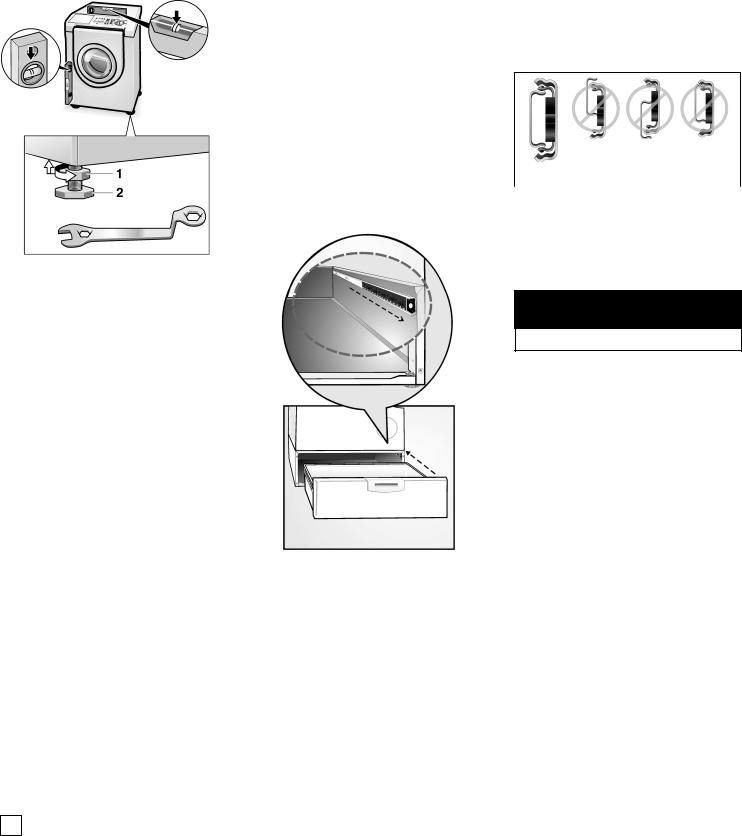
Figure |
17 |
|
|
q Turning the foot |
out |
(clockwise) |
|
will raise the |
corner |
of the |
|
appliance, turning the foot in (counter-clockwise) will lower the corner of the appliance.
When the corner of the |
|
|||
appliance |
is |
satisfactorily |
raised |
|
or |
lowered, |
lock the |
|
|
height-adjustable feet in |
place |
|||
by |
turning |
the lock nut |
|
|
counter-clockwise until it locks tightly against the pedestal housing.
Note: Correct |
adjustment |
of |
feet |
6. Replace |
the |
drawer |
by aligning it |
to |
|
(equal |
weight |
distribution |
to |
all feet) |
the drawer |
slides. |
Ensure slides |
of |
|
is required to minimize vibration |
pedestal and drawer are aligned |
|
|||||||
and movement of the appliance |
correctly |
(seeFigure |
19). |
|
|||||
during |
operation. |
|
|
|
|
|
|
|
|
4.Use the supplied 17mm open^end wrench to securely tighten both
locknuts |
for the |
front |
feet |
against |
|
|
|
|
the pedestal.All locknuts must |
|
|
|
|
||||
be tightened firmly |
to prevent |
|
|
Incorrect |
||||
the height adjustable feet from |
|
|
||||||
moving |
during |
appliance |
use. |
Correct |
|
|
|
|
5. Slide the ball bearing rails on the |
|
|
|
|
||||
|
Figure 19 |
|||||||
pedestal side to the front (see |
|
|||||||
Figure |
18). |
|
|
|
7. Close |
the |
drawer. |
|
|
|
|
|
|
||||
|
|
|
|
|
Ensure drawer slides are correctly |
|||
|
|
|
|
|
engaged by freely opening and |
|||
|
|
|
|
|
closing |
the |
drawer. |
|
d CAUTION
Do not use the drawer as a step.
For problems with or service on your pedestal contactBSH Home Appliances. Contact information is available in theCustomer• Service" section of the appliance manual.
|
i |
It may be necessary to hold |
|
|||
|
|
the appliance foot with a |
|
|||
|
|
pair of pliers to keep it from |
|
|||
|
|
turning while |
tightening |
the |
|
|
|
|
lock nut. |
It |
the foot |
does |
Figure 18 |
|
|
turn, it will change the |
|
|||
|
|
height of |
the |
corner. |
|
|
q After making |
preliminary |
|
|
|||
|
adjustments, |
press down |
on |
|
||
each corner of the appliance to make sure the unit does not wobble. If it does wobble, lower the foot on that corner until the foot touches the floor firmly.
3.For Washers:Fine tune the
leveling by placing a small load of laundry in the machine, starting it in spin cycle and then leveling the appliance again.
i If the test spin cycle is manually
stopped |
before |
its |
completion, |
|
then |
the |
door |
may |
remain locked |
for |
10 seconds. |
|
||
7

WARRANTY
Full |
OneVYear |
Warranty |
on |
Mechanical |
Parts |
|
|
|
|
|
|
|
|
||||||
For |
one |
year |
from the date |
of purchase, when this pedestal is |
installed with |
the listed washer or dryer and operate |
|||||||||||||
according |
to |
the instructions |
provided |
in |
the |
washer •Operating,or dryer |
Care and Installation Instructions", supplier will |
||||||||||||
repair or |
replace any of its mechanical parts if defective in material or workmanship. |
|
|
|
|||||||||||||||
Warranty |
Restriction |
|
|
|
|
|
|
|
|
|
|
|
|
|
|
|
|||
If the Pedestal is subject to |
other than private family use and/or used with any other product than those listed in t |
||||||||||||||||||
Installation |
Instructions, the warranty |
is null |
and void. |
|
|
|
|
|
|
|
|||||||||
Warranty |
Service |
|
|
|
|
|
|
|
|
|
|
|
|
|
|
|
|||
Warranty |
service is available |
by |
contacting the retailer where the |
Pedestal |
was |
purchased. If retailer is not available, |
|||||||||||||
the •Operating, |
Care |
and |
Installation |
Instructions"that |
came with |
the washer |
or |
dryer that |
is installed with the |
||||||||||
Pedestal |
and |
contact |
the |
service |
department |
listed |
there. |
|
|
|
|
|
|
|
|||||
This warranty applies only while |
the Pedestal |
is in use in the United States |
or Canada*. |
This |
warranty |
gives you sp |
|||||||||||||
you |
may |
also |
have |
other |
rights |
which vary from state to state |
or province |
to |
province. |
|
|
|
|||||||
*Warranty |
terms may |
vary |
in |
Canada. |
|
|
|
|
|
|
|
|
|
|
|
||||
In the space below, record |
the |
purchase |
date of your pedestal |
and model |
and serial number |
of the |
appliance on |
||||||||||||
pedestal |
is |
installed. |
|
|
|
|
|
|
|
|
|
|
|
|
|
|
|
||
Save these instructions and your sales receipt for future reference.
Purchase Date _____/_____/_______
Appliance Model Number
Appliance Serial Number
8
 Loading...