


VMD01 – M50 PAL
VMD01 – M60 NTSC
Security Systems
Operating instrutions
EN Video Motion Detector
Utilisation
FR Détecteur de mouvement vidéo
Bedienungsanleitung
DE Videobewegungssensor
Instucciones de servicio
SP Sensor de movimiento de vídeo
Handleiding
NL Videobewegingssensor
Instruzioni per l’uso
IT Sensore di movimento video
Manual de operação
PO Vídeo–sensor de movimentos
610–4.998.137.762 Ausgabe: 1
Stand: Februar 03

FCC
This equipment has been tested and found to comply with the limits for a Class B digital device, pursuant to Part 15 of the FCC Rules. These limits are designed to provide reasonable protection against harmful interference in a residential installation. This equipment generates, uses and can radiate radio frequency energy and, if not installed and used in accordance with the instructions, may cause harmful interference to radio communications. However, there is no guarantee that interference will not occur in a particular installation. If this equipment does cause harmful interference to radio or television reception, which can be determined by turning the equipment off and on, the user is encouraged to try to correct the interference by one or more of the following measures:
–Reorient or relocate the receiving antenna.
–Increase the separation between the equipment and receiver.
–Connect the equipment into an outlet on a circuit different from that to which the receiver is connected.
–Consult the dealer or an experienced radio/TV technican for help.
Recognized Component Mark for Canada and the United States
If the unit is used as a stand alone, it must be supplied via a power supply which fulfils the requirement on “SELV” and on a Limited Power Source.
If the unit is mounted into a 19” rack a suitable fire enclosure must be provided in the end–unit.
EU Declaration of Conformity
Bosch declares, this product: is conform to the following standards:
Supplementary Information: “The product complies with the requirements of the low Voltage Directive 73/23EEC and the EMC Directive 89/336/EEC.”
This product is carrying the CE–Mark in accordance with the related European Directives. Responsible for CE–Marking is
Bosch Sicherheitssysteme GmbH Security Systems Division Ludwig–Boelkow–Allee
85521 Ottobrunn Germany
– 2 – |
A1 February 03/Trb |

TABLE OF CONTENTS |
English |
|
|
Chapter |
Page |
|
1 |
Introduction |
38 |
2 |
Mounting |
39 |
3 |
Functions |
42 |
4 |
System structure |
44 |
5 |
Programming |
45 |
6 |
Operating instructions |
50 |
7 |
Technical data |
52 |
8 |
Notes |
53 |
Français |
20 |
German |
37 |
Español |
54 |
Italiano |
71 |
Dutch |
88 |
Portuguese |
105 |
Note:
Additional information about the product, installation, and operation can be found at: http://www.boschsecuritysystems.com
– 3 – |
A1 February 03/Trb |
1 Introduction
English
This is a high-quality single-channel video movement sensor for direct integration in an analog CCTV system.
Video signals are evaluated through image analysis and interpretation. Alarm, pre-alarm and post-alarm images are stored.
Additional information on project planning and the software tool can be obtained in electronic form through a dealer or installer.
Statutes/Norms/Guidelines met by the unit
–EMV law on the basis of
DIN EN 50081–1 (radiated noise) DIN EN 50130–4 (noise immunity)
–DIN EN 60950 (electrical safety)
–Environment to IEC 68–2–2/Degree I, 68–2–1, 68–2–30
The product carries the CE symbol. Registration: FCC
Registration: Recognition Component Mark for Canada and the United States (File number: E221534)
Basic shipment contents
–Basic device (VMD01–M50/M60)
–Operating instructions
–15-pin Sub–D plug
–Flat box with rubber feet and brackets
Accessories
–Power supply VMD–PS
–Wall holder VMD–WM
–Mouse VMD–SM
–19” frame incl. mounting VMD–RA90
–19”frame incl. mounting brackets without power supply/cable set/ Distributor LP, with blind plate VMD–RA00
–19” blind plate VMD–RADC
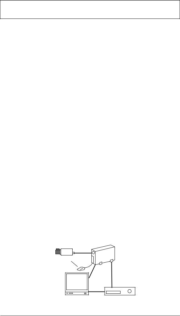
Camera, monitor, recorder, mouse (for programming) and cabling are not part of the shipment contents.
Only for programming
Alarm contact
– 4 – |
A1 February 03/Trb |
2 Mounting
English
2.1General mounting notes
–Use only cable specified by the manufacturer. Protection against malfunction cannot otherwise be guaranteed.
–To guarantee operational safety, only those power supplies specified by the manufacturer may be used. (individual devices: power supply VMD–PS, for 19” installation, the power supply is integrated in the VMD–RA frame).
–For questions regarding setup, environmental conditions and safety of individual components, manufacturer documentation must be consulted.
–For installation, this instruction manual and the specific connection instructions are to be followed.
–This description does not contain information about installation and setup of the camera, monitor and recorder.
2.1.1Mounting Variants
|
Unit feet |
|
|
1. Press in |
|
|
2. Press in |
|
|
|
Locking |
Feet |
3. Press down with blunt object |
spring |
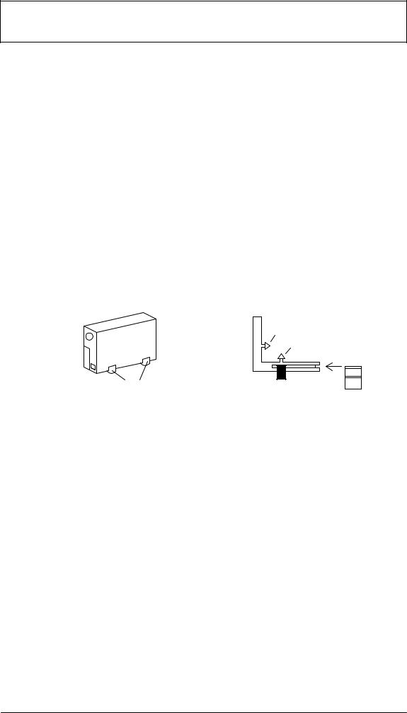
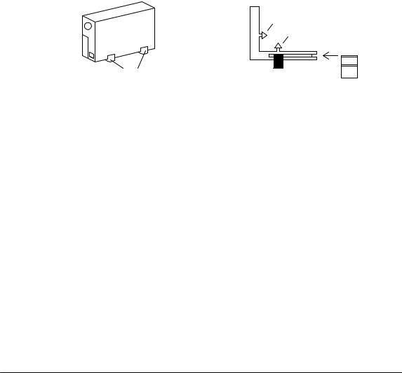
Housing vertical
Four feet must be fitted to the unit base plate. The connecting cable must have sufficient strain relief.
Housing can be stacked upright. Warning!
Maximum of four units can be stacked upright on top of each other.
If housings are stacked on top of each other, the feet on the underside of the housing must be fitted. There are no locking springs for the bottom unit. For all other units to be stacked, the locking springs must be pushed into the feet and pressed into the locating slits on the bottom unit. Ensure sufficient strain relief.
– 5 – |
A1 February 03/Trb |
Mounting continued |
English |
|
|
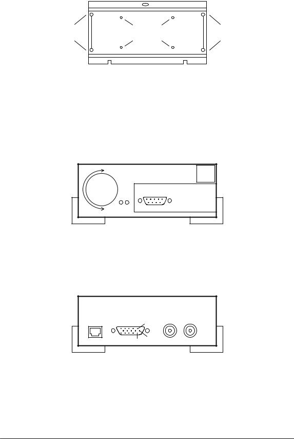
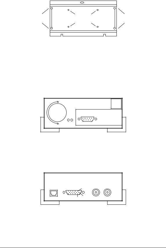
2.1.2Wall holder for mounting on walls and ceilings (accessory VMD–WM)
TOP |
|
TOP |
Holes for |
Mounting holes |
Holes for |
strain relief |
for housing |
strain relief |
The wall holder can be used as a drilling template. Before mounting on a wall, screw the wall holder (using fitting holes for housing) to the unit. For strain relief using cable ties, use the holes in the mounting plate.
Warning!
Only one unit may be mounted on a wall or ceiling.
2.1.3Connections / Front
|
3 |
|
4 |
|
|
|
|
|
|
1 2 |
|
1 |
L1 green |
2 |
L2 red |
3 |
Key/Rotary Switch |
4 |
Mouse connection, RS232 serial interface |
2.1.4Connections / Rear
|
1 |
2 |
1 |
3 |
4 |
|
|
11 |
6 |
|
|
1 |
5V DC |
2 |
I/O Contacts |
|
|
3 |
Video OUT |
4 |
Video IN |
|
|
– 6 – |
A1 February 03/Trb |

Mounting continued |
English |
|
|
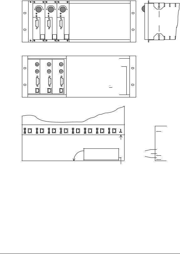
2.219” mounting frame and wiring (Accessory VMD–RA90)
Front
Maximum expansion |
mounting |
8 units |
bracket |
Rear

 Power supply
Top view (distributor LP)
Fuse = 2A
+5V
|
|
100–240V |
Power supply |
||
Direction of swivel
100–240V
L IEG 5V– +5V


For rack mounting, insert the mounting angle brackets (packaged extra) into the slides, screw down and feed the cabling through.
Warning
Grounding must be professionally carried out according to IEN 60950.
2.2.119” mounting frame without wiring (accessory VMD–RA00)
The frame is delivered without power supply/cable set/distributor LP, with blind plate.
– 7 – |
A1 February 03/Trb |

3 Functions
English
3.1Overlaid lines for color and B/W signals
Live and archived images |
Color |
|
Black/White |
|
Alarm object: |
Red |
Striped line with high contrast |
|
|
|
|
|
|
|
Pre-alarm object: |
Yellow |
Striped line with low contrast |
|
|
|
|
|
|
|
Tracking line: |
Green |
Striped line |
|
|
|
|
|
|
|
|
|
|
||
Configuration |
Color |
Black/White |
||
Area of sensitivity: |
Green |
Striped line |
||
|
|
|
||
Perspective: |
Green: Foreground |
Striped lines; |
||
|
Blue: Background |
Foreground square: Larger dotted line |
||
|
|
|
Background square: Smaller dotted line |
|
Directionality: |
Green: Direction |
Striped lines; |
||
|
Blue: Tolerance |
Directional arrow with smaller dotted lines |
||
|
|
|
Tolerance lines with larger dotted lines |
|
|
|
|
|
|
3.2 |
Rotary switch |
|
|
|
|
|
|
|
|
Operation |
Function |
|
|
Briefly press |
Alarm image memory on |
|
|
|
|
|
|
Briefly press again |
Alarm image memory off |
|
|
|
|
|
|
Long press (> 2 sec.) |
Acknowledge alarm |
|
|
|
|
|
|
Rotate right |
Forwards in alarm archive (+) |
|
|
|
|
|
|
Rotate left |
Backwards in alarm archive (–) |
3.3Light emitting diodes
LED |
Status |
Function |
|
L1 green |
off |
No supply of power to unit |
|
|
|
|
|
|
on |
Unit operating normally |
|
|
Blinking |
Unit malfunction as combined message |
|
|
Unit defective and/or video channel malfunction |
||
|
|
||
L2 red |
off |
No alarm, not armed |
|
(when L1 on) |
|||
|
|
||
|
|
|
|
|
on |
No alarm, armed |
|
|
|
|
|
|
Blinking |
Object detected/Alarm on |
|
|
|
|
|
L2 red |
off |
No malfunction on video signal, |
|
(when L1 blinking) |
unit malfunctioning |
||
|
|||
|
on |
No video signal, no general unit malfunction |
|
|
|
|
|
|
|
Video signal interference: |
|
|
Blinking |
1. Signal/Noise ratio too low |
|
|
2. Camera blinded |
||
|
|
||
|
|
3. Scene lighting level too low |
|
|
|
|
– 8 – |
A1 February 03/Trb |
Functions continued |
English |
|
|
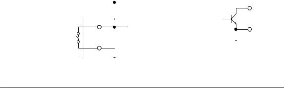
3.4Contact assignment
PIN |
Function |
|
|
|
|
|
|
|
|
|
|
|
|
|
Electrical specification |
|
|||||||||||||
|
|
|
|
|
|
|
|
|
|
|
|
|
|
|
|
|
|
|
|
|
|
|
|
|
|
|
|
|
|
1 |
Input contact I |
|
|
|
|
|
|
|
|
|
|
|
|
|
Internal pull-up |
|
|
||||||||||||
|
Open: sensor armed |
|
|
|
|
|
|
|
|
|
|
|
|
|
|
|
|
|
|
|
|
|
|||||||
|
At ground (Pin 5): Sensor disarmed |
|
|
|
|
|
|
|
|
|
|||||||||||||||||||
|
|
|
|
|
|
|
|
|
|
|
|
|
|
|
|
|
|
|
|
|
|
|
|
|
|
|
|
|
|
2 |
Input contact II |
|
|
|
|
|
|
|
|
|
|
|
|
|
Internal pull-up |
|
|
||||||||||||
|
Open: Parameter set I active |
|
|
|
|
|
|
|
|
|
|||||||||||||||||||
|
At ground (Pin 5): |
|
|
|
|
|
|
|
|
|
|
|
|
|
|
|
|
|
|
|
|
|
|||||||
|
Parameter set II active |
|
|
|
|
|
|
|
|
|
|
|
|
|
|
|
|
|
|
|
|
|
|||||||
|
|
|
|
|
|
|
|
|
|
|
|
|
|
|
|
|
|
|
|
|
|
|
|
|
|
|
|
|
|
3 |
Output contact I |
|
|
|
|
|
|
|
|
|
|
|
|
|
Open collector, |
|
|
||||||||||||
|
Internally switched to ground: Object detected |
max. 100mA, 12V |
|
|
|||||||||||||||||||||||||
|
Open: No object detected |
|
Externally switchable |
|
|||||||||||||||||||||||||
|
(constant signal, impulse or periodic impulse) |
|
|
|
|
|
|
|
|
||||||||||||||||||||
|
|
|
|
|
|
|
|
|
|
|
|
|
|
|
|
|
|
|
|
|
|
|
|
|
|
|
|
|
|
4 |
Output contact II |
|
|
|
|
|
|
|
|
|
|
|
|
|
Open collector, |
|
|
||||||||||||
|
Internally switched to ground: |
|
max. 100mA, 12V |
|
|
||||||||||||||||||||||||
|
Video signal malfunction |
|
Externally switchable |
|
|||||||||||||||||||||||||
|
Open: Video signal OK |
|
|
|
|
|
|
|
|
|
|
|
|
|
|
|
|
|
|
|
|
|
|||||||
|
|
|
|
|
|
|
|
|
|
|
|
|
|
|
|
|
|
|
|
|
|
|
|
|
|
|
|
|
|
5 |
Ground |
|
|
|
|
|
|
|
|
|
|
|
|
|
|
|
|
|
|
|
|
|
|||||||
6 |
Relay I |
|
|
|
|
|
|
|
|
|
|
|
|
|
Max. 30V, max. 1A |
|
|
||||||||||||
|
6/7 closed: Malfunction |
|
|
|
|
|
|
|
|
|
|
|
|
|
|
|
|
|
|
|
|
|
|||||||
|
|
|
|
|
|
|
|
|
|
|
|
|
|
|
|
|
|
|
|
|
|
|
|
|
|
|
|
|
|
7 |
Relay I (Middle contact) |
|
|
|
|
|
|
|
|
|
|
|
|
|
Max. 30V, max. 1A |
|
|
||||||||||||
|
|
|
|
|
|
|
|
|
|
|
|
|
|
|
|
|
|
|
|
|
|
|
|
|
|
|
|
|
|
8 |
Relay I |
|
|
|
|
|
|
|
|
|
|
|
|
|
Max. 30V, max. 1A |
|
|
||||||||||||
|
8/7 closed: No malfunction |
|
|
|
|
|
|
|
|
|
|||||||||||||||||||
|
|
|
|
|
|
|
|
|
|
|
|
|
|
|
|
|
|
|
|
|
|
|
|
|
|
|
|
|
|
9 |
Relay II |
|
|
|
|
|
|
|
|
|
|
|
|
|
Max. 30V, max. 1A |
|
|
||||||||||||
|
9/10 closed: No alarm |
|
|
|
|
|
|
|
|
|
|
|
|
|
|
|
|
|
|
|
|
|
|||||||
|
|
|
|
|
|
|
|
|
|
|
|
|
|
|
|
|
|
|
|
|
|
|
|
|
|
|
|
|
|
10 |
Relay II (Middle contact) |
|
Max. 30V, max. 1A |
|
|
||||||||||||||||||||||||
|
|
|
|
|
|
|
|
|
|
|
|
|
|
|
|
|
|
|
|
|
|
|
|
|
|
|
|
|
|
11 |
Relay II |
|
|
|
|
|
|
|
|
|
|
|
|
|
Max. 30V, max. 1A |
|
|
||||||||||||
|
11/10 closed: Alarm |
|
|
|
|
|
|
|
|
|
|
|
|
|
|
|
|
|
|
|
|
|
|||||||
|
|
|
|
|
|
|
|
|
|
|
|
|
|
|
|
|
|
|
|
|
|
|
|
|
|
|
|
|
|
12 |
Remote control Rotary switch: |
|
Internal pull-up |
|
|
||||||||||||||||||||||||
|
Backwards in alarm archive (–) when turned left |
|
|
|
|
|
|
|
|
||||||||||||||||||||
|
|
|
|
|
|
|
|
|
|
|
|
|
|
|
|
|
|
|
|
|
|
|
|
|
|
|
|
|
|
13 |
Remote control Rotary switch: |
|
Internal pull-up |
|
|
||||||||||||||||||||||||
|
– Switchover: Live image/alarm archive |
|
|
|
|
|
|
|
|
|
|||||||||||||||||||
|
– active >2 secs. = alarm acknowledgement |
|
|
|
|
|
|
|
|
||||||||||||||||||||
|
|
|
|
|
|
|
|
|
|
|
|
|
|
|
|
|
|
|
|
|
|
|
|
|
|
|
|
|
|
14 |
Remote control Rotary switch: |
|
Internal pull-up |
|
|
||||||||||||||||||||||||
|
Forwards in alarm archive (–) when turned right |
|
|
|
|
|
|
|
|
||||||||||||||||||||
|
|
|
|
|
|
|
|
|
|
|
|
|
|
|
|
|
|
|
|
|
|
|
|
|
|
|
|
|
|
15 |
Remote control Rotary switch: Ground |
|
|
|
|
|
|
|
|
|
|||||||||||||||||||
|
|
|
|
|
|
|
|
|
|
|
|
|
|
|
|
|
|
|
|
|
|
|
|
|
|
|
|
|
|
Input contacts |
|
|
|
|
|
+5V |
Output contacts |
3/4 |
|
||||||||||||||||||||
|
|
|
|
|
|
||||||||||||||||||||||||
Remote control |
|
|
|
|
|
|
|
|
|
|
|
|
|
|
|
|
|
|
|
|
|
|
|
|
|
|
|||
|
1/2 |
|
|
|
|
|
|
|
|
|
|
|
|
|
|
|
|
|
|
|
|
|
|
|
|
|
|
|
|
|
12/13/14 |
|
|
|
|
|
|
|
|
|
|
|
|
|
|
|
|
|
|
|
|
|
|
|
|
– |
|||
|
|
|
|
|
|
|
|
|
|
|
|
|
|
|
|
|
|
|
|
|
|
|
|
|
|
|
|
5/15 |
|
|
5/15 |
|
|
|
|
|
|
|
|
|
|
|
|
|
|
|
|
|
|
|
|
|
|
|
|
|
|
|
|
|
|
|
|
|
|
|
|
|
|
|
|
|
|
|
|
|
|
|
|
|
|
|
|
|
|
|
|
|
|
|
|
|
|
|
|
|
|
|
|
|
|
|
|
|
|
|
|
|
|
|
|
|
|
|
|
|
|
|
|
– 9 – |
A1 February 03/Trb |
4 System structure
English
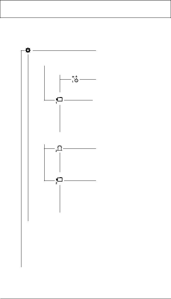
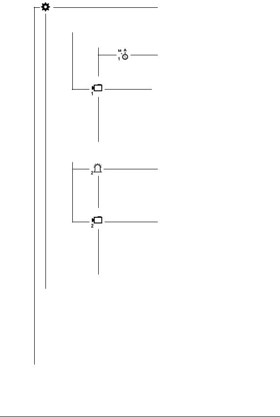
4.1Menu
Programming

 Parameter set 1

 Alarm set 1
Operating mode set 1


 Alarm contact set 1
Sensor parameter set 1

 Area of sensitivity set 1

 Object size/Perspective set 1

 Direction of movement set 1

 Parameter set 2 Alarm set 2

 Operating mode set 2

 Alarm contact set 2
Sensor parameter set 2

 Area of sensitivity set 2

 Object size/Perspective set 2

 Direction of movement set 2
 Copy parameter set


 Language

 Change code number


 System information
 Exit
Exit
– 10 – |
A1 February 03/Trb |
5 Programming
English
5.1Startup
The unit should be started up at room temperature.
Before starting up, ensure that all components are correctly connected. Follow mounting instructions!
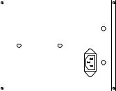
Menu screen
1 |
Work area/Live image |
|
3 |
|
|
|
|||
2 |
Help text |
1 |
|
|
3 |
Company logo |
4 |
||
|
||||
4 |
User navigation |
|
|
|
|
|
2 |
|
5.1.1Operation
When setting up, please use the menu tree and the help text in the lower monitor window. The following symbols are used for navigation:
 = Cancel (dismiss entry, return to higher level)
 = Confirm (accept entry, return to higher menu level)
= Correct (delete current entry)
= One level back
= Exit
Unless otherwise stated, the left mouse button is used for drawing and pasting and the right mouse button for deleting.
5.1.2Code number (default 00000) / Change code number
After switch-on or after selecting “Exit” from the programming screen, there is a delay of around 5 seconds before the mouse can be moved to enter the code mask.
Change code number : Enter the new code number twice.
– 11 – |
A1 February 03/Trb |
Programming, continued |
English |
|
|
5.2Programming
 Starting programming
 Parameter set 1 or
  = Parameter set 2
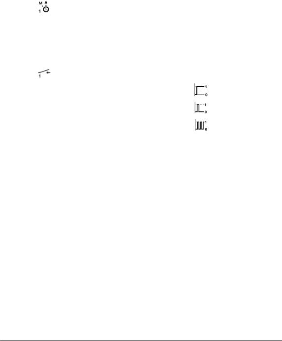
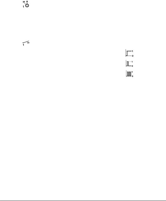
5.2.1 Alarm set 1 or 2
Operating type
Automatic acknowledgement, live image on alarm
Manual acknowledgement, live image on alarm
Manual acknowledgement, alarm image on alarm
See also chapter 6
Alarm contacts (contact output I see 3.4)
Continuous signal during object detection
Impulse on new object detection
Periodic signal during object detection
Signaling of alarms
|
LED red |
Relay II |
Output |
|
|
Blinking |
contacts |
||
|
|
|||
|
|
|
|
|
Automatic |
As long |
As long |
As long as |
|
as |
as |
object |
||
acknowl- |
||||
object |
object |
detected |
||
edgement |
||||
detected |
detected |
or impulse |
||
|
||||
|
|
|
|
|
Manual |
As long |
As long |
As long as |
|
as |
as |
object |
||
acknowl- |
||||
Alarm |
Alarm |
detected |
||
edgement |
||||
on |
on |
or impulse |
||
|
||||
|
|
|
|
– 12 – |
A1 February 03/Trb |

Programming, continued |
English |
|
|
5.2.2 Sensor parameter set 1 or 2
See chapter 3.1 (overlaid lines)
Area of sensitivity set 1 or 2
 The live image is shown with the sensitive, undarkened area. With the right mouse button pressed, square non-sensitive areas can be pulled up. After releasing the mouse button these are darkened and shown. Multiple non-sensitive areas of different sizes can be distributed on the image. With the left mouse button, non-sensitive areas can be deleted or modified by drawing over them; sensitive areas can be added with the right mouse button.
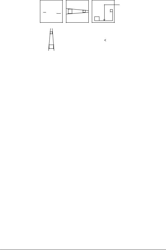
Drawing in object size/perspective set 1 or 2
 The live image is shown with a small rectangle. Its size is the factory-set default, not the minimum size. No perspective is set. Everything larger than the plotted rectangle is detected. The frame can be changed in size, moved about on the image, or another frame pulled up using the left mouse button. The larger frames show the minimum object size to be detected in the foreground. The smaller frames show the minimum object size in the background. The position of the frames relative to each other shows the perspective set. Note that the position of the perspective always only runs horizontally or vertically, even when the rectangles on the image are arranged diagonally. If one thinks of both rectangles as the endpoint of an “L” lying parallel to the image edges, the longer side indicates the position. If the relative sizes of the frames are changed, the colors or types of lines also change. The rectangles can be deleted by dragging a frame with the right mouse button. If both rectangles are deleted, the small rectangle reappears.
– 13 – |
A1 February 03/Trb |
Programming, continued |
English |
|
|
Example of perspective positioning
Longer side (horizontal perspective)
Horizontal
Vertical |
|
|
|
|
|
|
|
|
Longer side |
|
|
|
|
|
|
|
|
||
|
|
|
|
|
|
|
|
||
|
|
|
|
|
|
|
|
(vertical perspective) |
|
|
|
|
|
|
|
|
|
|
|
|
|
|
|
|
|
|
|
|
|
|
|
|
|
|
|
|
|
|
|
Direction of movement set 1 or 2
 The live image is shown with a small rectangle in the middle of the image and all movements lead to an alarm being triggered. No permitted direction of movement is plotted.
Plotting the permitted direction of movement:
The permitted direction of movement is plotted by pressing the left mouse button in the live image. This is marked by an arrow with two tolerance lines. These two lines represent the tolerance in the permitted direction of movement. If the cursor is moved to the arrow tips or the tolerance lines, the cursor symbol changes. The arrow and tolerance lines can be rotated and the tolerance lines opened up or made narrower with the left mouse button.
Pressing the mouse button in the opposite arrow direction results in the appearance of a second arrow with tolerance lines being plotted on the image. The arrows and tolerance lines can be deleted by dragging a frame over them with the right mouse button.
5.2.3Copy parameter sets
 Parameter set 2 becomes a copy of set 1, or 1 of set 2.
– 14 – |
A1 February 03/Trb |

Programming, continued |
English |
|
|
5.2.4Saving parameter sets
For this, use the service program VMD01Service.exe on a PC. Connect the PC’s serial interface to the unit’s RS232 interface via a null-modem cable. To save, call the program with the parameter ‘–pd’. The parameter data is saved in a file in the same directory as the software. The file name may look as follows “VMD01ParaXXXXX”. XXXXX here represents the unit ID. The parameter data can be played back in with the tool. The parameter ‘–pu’ and the parameter file are entered for this purpose. This allows copying of parameter sets from one unit to another.
– 15 – |
A1 February 03/Trb |

6 |
Operating instructions |
English |
|
|
|
6.1Acknowledge / Alarm images
All parts of the system are switched on, operational and programmed. The live image can be seen on the monitor. The green and red LEDs are lit. An operating mode has been programmed.
Operating mode
Automatic acknowledgement, live image on alarm
If an alarm has occurred, the live image is shown with overlaid masks. The alarm is automatically acknowledged. If a subsequent alarm is detected, the previous alarm images are deleted. The alarm memory always contains the newest alarm.
Manual acknowledgement, live image on alarm
If an alarm has occurred, the live image is shown with overlaid masks. The system remains armed. A subsequent alarm does not store new alarm images, but is signaled at the output contact. The alarm image memory always contains the oldest unacknowledged alarm. The live image appears after manual acknowledgement.
Manual acknowledgement, alarm image on alarm
If an alarm has occurred, the alarm image (No. 0) is shown with overlaid masks. The masks will disappear after 5 seconds. The system is still armed. A subsequent alarm does not store new alarm images, but is signaled at the output contact. The alarm image memory always contains the oldest unacknowledged alarm. The live image appears after manual acknowledgement.
Alarm acknowledgement
If an alarm occurs, the red LED blinks.
The alarm is acknowledged by pressing (> two seconds) the key/rotary switch. The red LED then switches from blinking to steadily lit (not for AQL).
– 16 – |
A1 February 03/Trb |

Operating instructions, continued |
English |
|
|
Access to alarm image memory:
Alarm images can be viewed before or after acknowledgement. To switch from live images to alarm images, briefly press the key/rotary switch.
No alarm images present =  .
.
If alarm images are present, a display “0“ appears in the monitor picture, i.e. the alarm occurred at this point in time.
Rotate the key/rotary switch to the:
left, for pre-alarm images “–” right, for post-alarm images “+”. The object causing the alarm is outlined in red in the alarm image and in the post-alarm image. The first detection of the object is outlined in yellow. Movement of the object is outlined with a green line between the yellow and red lines. See also chapter 3.1 (Overlaid lines for color and B/W signals). If an image is displayed for longer than 5 seconds, the lines will disappear. Upon switching further to pre or post-alarm images, these will first be displayed with masks. The alarm mode is exited by briefly pressing again. There is a switch to the live image if no operation in the alarm memory is carried out within 60 seconds.
– 17 – |
A1 February 03/Trb |

7 Technical data
English
7.11 channel variant
Main memory |
|
|
|
|
|
|
32MB RAM |
|||||||||||||||||||||||||||||
Video input |
|
|
|
|
|
|
1 x BNC, PAL (CCIR) / NTSC (EIA), |
|||||||||||||||||||||||||||||
|
|
|
|
|
|
|
|
|
|
|
|
|
|
|
|
|
|
|
|
|
|
|
|
|
|
|
|
|
|
|
|
|
|
|
75Ω internal, 1Vss (0.5–2.0Vss) |
|
Video output |
|
|
|
|
|
|
1 x BNC, PAL (CCIR) / NTSC (EIA), 1Vss |
|||||||||||||||||||||||||||||
Input contacts |
|
|
|
|
|
|
Internal pull-up |
|||||||||||||||||||||||||||||
Contact outputs |
Open collector 100mA/12V ext. switchable |
|||||||||||||||||||||||||||||||||||
Relay outputs |
|
|
|
|
|
|
max. 30V, max. 1A |
|||||||||||||||||||||||||||||
Connections (Rear) |
see Mounting |
|||||||||||||||||||||||||||||||||||
Connections (Front) |
see Mounting |
|||||||||||||||||||||||||||||||||||
Serial interface |
RS232 (Saving data/Mouse connector) |
|||||||||||||||||||||||||||||||||||
Weight |
|
|
|
|
|
|
|
|
|
|
|
|
|
|
|
|
|
|
approx. 0.5 kg |
|||||||||||||||||
|
|
|
|
|
|
|
|
|
|
|
|
|
|
|
|
|
|
|
|
|
|
|
|
|
|
|
|
|
|
|
|
|
|
|
(without power supply and mouse) |
|
Dimensions (H x W x D) |
approx. 110mm x 48mm x 207mm |
|||||||||||||||||||||||||||||||||||
Storage temperature |
233 K ... 343 K (–40° C ... +70°C) |
|||||||||||||||||||||||||||||||||||
Relative humidity in storage |
8% ... 80% (relative humidity) |
|||||||||||||||||||||||||||||||||||
Operational temperature |
273 K ... 318 K (+0° C ... +45°C) |
|||||||||||||||||||||||||||||||||||
Relative humidity in operation |
15% ... 80% (relative humidity) |
|||||||||||||||||||||||||||||||||||
Current consumption |
5W/1.2A |
|
||||||||||||||||||||||||||||||||||
Pin assignments: Power supply: |
|
|
||||||||||||||||||||||||||||||||||
6 |
|
|
|
|
|
|
|
|
|
|
|
|
|
1 |
|
|
|
|
|
|
|
|
|
PIN1 = +5V |
PIN4 = GND |
|||||||||||
|
|
|
|
|
|
|
|
|
|
|
|
|
|
|
|
6 |
|
|
|
|
|
|||||||||||||||
|
|
|
|
|
|
|
|
|
|
|
|
|
|
|
|
|
|
|
|
|
|
|
|
|
|
|
|
|
|
|
|
|
|
|
PIN2 = +5V |
PIN5 = nc |
|
|
|
|
|
|
|
|
|
|
|
|
|
|
|
|
|
|
|
|
|
|
|
|
|
|
|
|
|
|
|
|
|
|
|
||
|
|
|
|
|
|
|
|
|
|
|
|
|
|
|
|
|
|
|
|
|
|
|
|
|
|
|
|
|
|
|
|
|
|
|
PIN3 = nc |
PIN6 = GND |
|
|
|
|
|
|
|
|
|
|
|
|
|
|
|
|
|
|
|
|
|
|
|
|
|
|
|
|
|
1 |
|
|
|
|
|
||
Power supply in 19” rack |
|
|
||||||||||||||||||||||||||||||||||
D Input voltage |
100–240 VAC / 50–60Hz |
|||||||||||||||||||||||||||||||||||
D Output voltage |
5 VDC / 100VA |
|||||||||||||||||||||||||||||||||||
7.2Wall holder
Dimensions (H x W x D) |
approx. 205mm x 164mm x 10mm |
Weight |
approx. 0.4 kg |
For the model PAL or NTSC, please see the type label.
Subject to technical changes
– 18 – |
A1 February 03/Trb |
8 Notes
English
8.1General
If errors or malfunctions occur, the plug-in connectors should be checked first. A malfunction can sometimes be cured by briefly unplugging and re-plugging the power cord on the unit.
The unit may not be opened. Guarantee claims are rendered invalid if the seal is broken.
Description of the LEDs: See the Functions chapter.
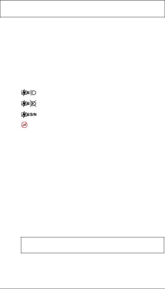
Superimposed malfunction indications for video signal malfunctions
= Camera blinded
= Scene lighting level too low
= Signal/noise ratio too low
= No video signal present
Reset to default setting
Unplug contact plugs and power supply from unit. Keep rotary switch pressed, plug power supply back in. The green LED lights. Keep the rotary switch pressed until the red LED lights (or blinks if an object is detected simultaneously). Immediately rotate the still-pressed rotary switch, wait until the red LED goes out and release the rotary switch. When the live image appears, the reset procedure is finished.
Notes
The video movement sensor is delivered with software already installed. For questions about the product, please consult your dealer.
Cleaning
Protect the unit from dust and moisture. Do not use aggressive cleaning agents.
All unusable parts of the video systems must be professionally disposed of.
– 19 – |
A1 February 03/Trb |

TABLE DES MATIERES |
Français |
|
|
Chapitre |
Page |
|
1 |
Introduction |
38 |
2 |
Montage |
39 |
3 |
Fonctions |
42 |
4 |
Structure du système |
44 |
5 |
Paramétrage |
45 |
6 |
Utilisation |
50 |
7 |
Données techniques |
52 |
8 |
Conseils |
53 |
Remarque :
Pour plus d’informations sur ce produit, son installation et son utilisation, visitez le site http://www.boschsecuritysystems.com
– 20 – |
A1 February 03/Trb |
1 |
Introduction |
Français |
|
|
|
Détecteur de mouvement vidéo monocanal de qualité supérieure pour intégration directe dans un système de télévision en circuit fermé analogique. Exploitation des signaux vidéo par analyse d’images et interprétation. Enregistrement des images de pré-alarme, d’alarme et de post-alarme.
Un complément d’informations sur la conception du projet et l’outil logiciel est disponible sous forme électronique auprès de votre revendeur ou de votre installateur.
Lois / normes / directives auxquelles l’appareil est conforme
–Loi sur la compatibilité électromagnétique (CEM) sur la base des normes suivantes
DIN EN 50081–1 (émissions) DIN EN 50130–4 (immunité)
–DIN EN 60950 (sécurité électrique)
–Environnement suivant IEC 68–2–2/niveau d’essai d’immunité I, 68–2–1, 68–2–30
Le produit porte la marque CE. Homologation : FCC
Homologation : Recognition Component Mark for Canada and the United States (Filenumber : E221534)
Contenu du module de base |
Accessoires |
||
– |
Appareil de base (VMD01–M50/M60) |
– |
Bloc d’alimentation enfichable |
|
|
|
VMD–PS |
– |
Mode d’emploi |
– |
Support mural VMD–WM |
– Connecteur Sub–D 15 pôles |
– |
Souris VMD–SM |
|
– Sachet avec pieds en caoutchouc et |
– Châssis 19” avec support |
||
|
pinces |
|
VMD–RA90 |
|
|
– Châssis 19” avec support |
|
|
|
|
sans unité d’alimentation / |
|
|
|
jeu de câbles / |
|
|
|
carte imprimée répartiteur, |
|
|
|
avec plaque obturatrice |
|
|
|
VMD–RA00 |
|
|
– |
Plaque obturatrice 19” |
|
|
|
VMD–RADC |
Caméra, moniteur, enregistreur, souris (pour le paramétrage) et câbles non fournis.
Uniquement pour le paramétrage
Contact d’alarme
– 21 – |
A1 February 03/Trb |
2 |
Montage |
Français |
|
|
|
2.1Instructions de montage générales
–Utilisez exclusivement le câble recommandé par le fabricant, faute de quoi la protection contre les interférences ne sera pas assurée.
–Pour garantir la sécurité de fonctionnement, seules les unités d’alimentation recommandées par le fabricant peuvent être utilisées. (Appareils individuels : bloc d’alimentation VMD–PS, lors du montage 19”, le bloc d’alimentation est intégré dans le châssis VMD–RA).
–Pour les questions relatives à l’installation, les conditions ambiantes, la sécurité des différents composants matériels, consultez impérativement la documentation du fabricant.
–Lors de l’installation, il convient de respecter ce mode d’emploi et les conditions de connexion en vigueur.
–Ce manuel ne décrit pas l’installation et la disposition de la caméra, du moniteur et de l’enregistreur.
2.1.1Variantes de montage
Pied de l’appareil
1. Enfoncer
2. Enfoncer
|
3. Enfoncer avec un objet épointé |
Ressort |
Pieds |
d’arrêt |
Boîtier vertical
Quatre pieds doivent être montés sous le boîtier. Il convient de veiller à une décharge de traction suffisante du câble de connexion.
Boîtier horizontal, empilable Attention !
Un maximum de quatre appareils peuvent être empilés horizontalement.
En cas d’empilage horizontal des boîtiers, les pieds doivent être montés sous les boîtiers. Le dernier appareil de la pile ne comporte pas de ressorts d’arrêt. Pour tous les autres appareils à empiler, les ressorts d’arrêt doivent être insérés dans les pieds et enfoncés dans les fentes du boîtier inférieur. Prévoyez une décharge de traction suffisante.
– 22 – |
A1 February 03/Trb |
Suite Montage |
Français |
|
|
2.1.2Support pour montage mural et au plafond (accessoire VMD–WM)
HAUT |
HAUT |
|
Trous pour |
Trous de centrage |
Trous pour |
décharge de traction |
du boîtier |
décharge de traction |
Vous pouvez utiliser le support mural comme gabarit de perçage. Avant le montage mural, vissez le support (trous de centrage du boîtier) sur l’appareil. Utilisez les trous de la plaque de montage pour la décharge de traction avec serre-câbles.
Attention !
Vous ne pouvez monter qu’un seul appareil au mur ou au plafond.
2.1.3Connexions / Face avant
|
3 |
4 |
|
|
|
|
|
|
1 2 |
|
|
1 |
L1 vert |
2 |
L2 rouge |
3 |
Poussoir / Commutateur rotatif |
4 |
Port souris, port série RS232 |
2.1.4Connexions / Face arrière
|
1 |
2 |
1 |
3 |
4 |
|
|
11 |
6 |
|
|
1 |
5 V c.c. |
|
|
2 |
Contacts E/S |
3 |
Sortie vidéo |
|
|
4 |
Entrée vidéo |
– 23 – |
A1 February 03/Trb |
Suite Montage |
Français |
|
|
2.2Châssis de montage 19” et câblage (Accessoires VMD–RA90)
Face avant
Configuration |
Equerre |
maximale |
de montage |
8 appareils |
|
Face arrière
 Unité d’alimentation
Vue de dessus (carte imprimée répartiteur)
Si = 2A
+5V |
|
||
Unité d’alimentation |
|
|
100 – 240 V |
|
|
||
|
|
|
|
Sens de pivotement
100 – 240 V
L NEG 5V– +5V


Pour le montage dans le tiroir, placez et insérez-y l’équerre de montage (jointe), vissez et procédez au câblage.
Attention !
La mise à la terre doit être effectuée conformément à IEN 60950.
2.2.1Châssis de montage 19” sans câblage (accessoire VMD–RA00)
Le châssis est fourni sans unité d’alimentation/jeu de câbles/carte imprimée répartiteur, avec plaque obturatrice.
– 24 – |
A1 February 03/Trb |

3 |
Fonctions |
Français |
|
|
|
3.1Lignes de brouillage pour les signaux couleur et N/B
Images en direct et d’archive |
Couleur |
Noir/blanc |
Objet d’alarme : |
Rouge |
Ligne hachurée avec contraste élevé |
|
|
|
Objet de pré-alarme : |
Jaune |
Ligne hachurée avec contraste faible |
|
|
|
Ligne de tracking : |
Vert |
Ligne hachurée |
|
|
|
Paramétrage |
Couleur |
Noir/blanc |
Zone sensible : |
Vert |
Ligne hachurée |
|
|
|
Perspective : |
Vert : avant-plan |
Lignes hachurées ; |
|
Bleu : arrière-plan |
Rectangle avant-plan : grands traits |
|
|
Rectangle arrière-plan : traits plus petits |
Directionnalité : |
Vert : direction |
Lignes hachurées ; |
|
Bleu : tolérance |
Flèche directionnelle avec petits traits |
|
|
Lignes de tolérance avec grands traits |
|
|
|
3.2Commutateur rotatif
Action |
Fonction |
|
Brève pression |
Activation de la mémoire d’images d’alarme |
|
|
|
|
Nouvelle brève pression |
Désactivation de la mémoire d’images d’alarme |
|
|
|
|
Longue pression (> 2 s) |
Confirmation de l’alarme |
|
|
|
|
Rotation vers la droite |
Progression dans l’archive des alarmes (+) |
|
|
|
|
Rotation vers la gauche |
Recul dans l’archive des alarmes (–) |
|
3.3Diodes électroluminescentes
LED |
Etat |
Fonction |
|
L1 vert |
Eteint |
Appareil hors tension |
|
|
|
|
|
|
Allumé |
Appareil en service sans panne |
|
|
Clignotant |
Panne de l’appareil comme message collectif |
|
|
Appareil défectueux et/ou panne du canal vidéo |
|
|
|
|
|
|
|
|
|
|
L2 rouge |
Eteint |
Aucune alarme, non amorcée |
|
(avec L1 allumé) |
|
||
|
|
|
|
|
|
|
|
|
Allumé |
Aucune alarme, amorcée |
|
|
|
|
|
|
Clignotant |
Objet détecté / alarme en attente |
|
|
|
|
|
L2 rouge |
Eteint |
Aucune défaillance du signal vidéo, |
|
(avec L1 clignotant) |
panne de l’appareil |
|
|
|
|
||
|
Allumé |
Aucun signal vidéo, aucune panne générale de l’appareil |
|
|
|
|
|
|
|
Défaillance du signal vidéo : |
|
|
Clignotant |
1. Signal utile / de bruit trop faible |
|
|
2. Caméra éblouie |
|
|
|
|
|
|
|
|
3. Eclairage de scène trop faible |
|
|
|
|
|
– 25 – |
A1 February 03/Trb |

Suite Fonctions |
Français |
|
|
3.4Configuration des contacts
Broche |
|
Fonction |
|
Spécification électr. |
|
||||||||||||||||||||||||
|
|
|
|
|
|
|
|
|
|
|
|
|
|
|
|
|
|
|
|
|
|
|
|
|
|
|
|
|
|
1 |
Entrée de contact I |
|
pull-up interne |
|
|
||||||||||||||||||||||||
|
ouvert : détecteur amorcé |
|
|
|
|
|
|
|
|
|
|||||||||||||||||||
|
sur Ground (broche 5) : détecteur pas amorcé |
|
|
|
|
|
|
|
|
||||||||||||||||||||
|
|
|
|
|
|
|
|
|
|
|
|
|
|
|
|
|
|
|
|
|
|
|
|
|
|
|
|
|
|
2 |
Entrée de contact II |
|
pull-up interne |
|
|
||||||||||||||||||||||||
|
ouvert : jeu de paramètres I actif |
|
|
|
|
|
|
|
|
|
|||||||||||||||||||
|
sur Ground (broche 5) : |
|
|
|
|
|
|
|
|
|
|||||||||||||||||||
|
jeu de paramètres II actif |
|
|
|
|
|
|
|
|
|
|||||||||||||||||||
|
|
|
|
|
|
|
|
|
|
|
|
|
|
|
|
|
|
|
|
|
|
|
|
|
|
|
|
|
|
3 |
Sortie de contact I |
|
Open-Collector, |
|
|
||||||||||||||||||||||||
|
basculement interne sur Ground : objet détecté |
max. 100 mA, 12 V |
|
|
|||||||||||||||||||||||||
|
ouvert : aucun objet détecté |
|
connexion externe |
|
|
||||||||||||||||||||||||
|
(signal continu, impulsion ou impulsion |
|
|
|
|
|
|
|
|
|
|||||||||||||||||||
|
périodique) |
|
|
|
|
|
|
|
|
|
|
|
|
|
|
|
|
|
|
|
|
|
|
|
|
|
|
|
|
|
|
|
|
|
|
|
|
|
|
|
|
|
|
|
|
|
|
|
|
|
|
|
|
|
|
|
|
|
|
4 |
Sortie de contact II |
|
Open-Collector, |
|
|
||||||||||||||||||||||||
|
basculement interne sur Ground : |
|
max. 100 mA, 12 V |
|
|
||||||||||||||||||||||||
|
défaillance du signal vidéo |
|
connexion externe |
|
|
||||||||||||||||||||||||
|
ouvert : signal vidéo correct |
|
|
|
|
|
|
|
|
|
|||||||||||||||||||
|
|
|
|
|
|
|
|
|
|
|
|
|
|
|
|
|
|
|
|
|
|
|
|
|
|
|
|
|
|
5 |
Ground |
|
|
|
|
|
|
|
|
|
|
|
|
|
|
|
|
|
|
|
|
|
|
|
|
|
|
|
|
6 |
Relais I |
|
|
|
|
|
|
|
|
|
|
|
|
|
|
|
|
|
|
|
|
max. 30 V, max. 1 A |
|
||||||
|
6/7 fermé : panne |
|
|
|
|
|
|
|
|
|
|||||||||||||||||||
|
|
|
|
|
|
|
|
|
|
|
|
|
|
|
|
|
|
|
|
|
|
|
|
|
|
|
|
||
7 |
Relais I (contact central) |
|
max. 30 V, max. 1 A |
|
|||||||||||||||||||||||||
|
|
|
|
|
|
|
|
|
|
|
|
|
|
|
|
|
|
|
|
|
|
|
|
|
|
|
|
|
|
8 |
Relais I |
|
|
|
|
|
|
|
|
|
|
|
|
|
|
|
|
|
|
|
|
max. 30 V, max. 1 A |
|
||||||
|
8/7 fermé : aucune panne |
|
|
|
|
|
|
|
|
|
|||||||||||||||||||
|
|
|
|
|
|
|
|
|
|
|
|
|
|
|
|
|
|
|
|
|
|
|
|
|
|
|
|
|
|
9 |
Relais II |
|
|
|
|
|
|
|
|
|
|
|
|
|
|
|
|
|
|
|
|
max. 30 V, max. 1 A |
|
||||||
|
9/10 fermé : aucune alarme |
|
|
|
|
|
|
|
|
|
|||||||||||||||||||
|
|
|
|
|
|
|
|
|
|
|
|
|
|
|
|
|
|
|
|
|
|
|
|
|
|
|
|
||
10 |
Relais II (contact central) |
|
max. 30 V, max. 1 A |
|
|||||||||||||||||||||||||
|
|
|
|
|
|
|
|
|
|
|
|
|
|
|
|
|
|
|
|
|
|
|
|
|
|
|
|
|
|
11 |
Relais II |
|
|
|
|
|
|
|
|
|
|
|
|
|
|
|
|
|
|
|
|
max. 30 V, max. 1 A |
|
||||||
|
11/10 fermé : alarme |
|
|
|
|
|
|
|
|
|
|||||||||||||||||||
|
|
|
|
|
|
|
|
|
|
|
|
|
|
|
|
|
|
|
|
|
|
|
|
|
|
|
|
|
|
12 |
Télécommande commutateur rotatif : |
|
pull-up interne |
|
|
||||||||||||||||||||||||
|
vers la gauche (–), retour dans l’arch. alarmes |
|
|
|
|
|
|
|
|
||||||||||||||||||||
|
|
|
|
|
|
|
|
|
|
|
|
|
|
|
|
|
|
|
|
|
|
|
|
|
|
|
|
|
|
13 |
Télécommandecommutateur rotatif : |
|
pull-up interne |
|
|
||||||||||||||||||||||||
|
– Basculement : Image en direct / arch. alarmes |
|
|
|
|
|
|
|
|
|
|||||||||||||||||||
|
– actif>2 s = sortie du mode alarme |
|
|
|
|
|
|
|
|
|
|||||||||||||||||||
|
|
|
|
|
|
|
|
|
|
|
|
|
|
|
|
|
|
|
|
|
|
|
|
|
|
|
|
|
|
14 |
Télécommandecommutateur rotatif : |
|
pull-up interne |
|
|
||||||||||||||||||||||||
|
vers la droite (+), progression dans l’arch. alarmes |
|
|
|
|
|
|
|
|
||||||||||||||||||||
|
|
|
|
|
|
|
|
|
|
|
|
|
|
|
|
|
|
|
|
|
|
|
|
|
|
|
|
||
15 |
Télécommande commutateur rotatif : Ground |
|
|
|
|
|
|
|
|
||||||||||||||||||||
|
|
|
|
|
|
|
|
|
|
|
|
|
|
|
|
|
|
|
|
|
|
|
|
|
|
|
|
|
|
Entrées de contact |
|
|
|
|
|
|
|
+5V |
Sorties de contact |
3/4 |
|
||||||||||||||||||
|
|
|
|
|
|
|
|
||||||||||||||||||||||
Télécommande |
1/2 |
|
|
|
|
|
|
|
|
|
|
|
|
|
|
|
|
|
|
|
|
|
|
|
|
|
|
|
|
|
|
|
|
|
|
|
|
|
|
|
|
|
|
|
|
|
|
|
|
|
|
|
|
|
|
|
|||
|
|
|
|
|
|
|
|
|
|
|
|
|
|
|
|
|
|
|
|
|
|
|
|
|
|
|
|
|
|
|
12/13/14 |
|
|
|
|
|
|
|
|
|
|
|
|
|
|
|
|
|
|
|
|
|
|
|
– |
||||
|
|
|
|
|
|
|
|
|
|
|
|
|
|
|
|
|
|
|
|
|
|
|
|
|
|
|
|
5/15 |
|
|
|
5/15 |
|
|
|
|
|
|
|
|
|
|
|
|
|
|
|
|
|
|
|
|
|
|
|
|
|
|
|
|
|
|
|
|
|
|
|
|
|
|
|
|
|
|
|
|
|
|
|
|
|
|
|
|
|
|
|
|
|
|
|
|
|
|
|
|
|
|
|
|
|
|
|
|
|
|
|
|
|
|
|
|
|
|
|
|
|
|
|
– 26 – |
A1 February 03/Trb |
4 |
Structure du système |
Français |
|
|
|
4.1Menus
Paramétrage

 Jeu de paramètres 1

 Alarmes – Jeu 1
Modes de fonctionnement – Jeu 1


 Contacts d’alarme – Jeu 1
Paramètres de détection – Jeu 1

 Zones sensibles – Jeu 1

 Tailles d’objets / perspectives – Jeu 1

 Direction du mouvement – Jeu 1

 Jeu de paramètres 2
Alarmes – Jeu 2

 Modes de fonctionnement – Jeu 2

 Contacts d’alarme – Jeu 2
Paramètres de détection – Jeu 2

 Zones sensibles – Jeu 2

 Tailles d’objets / perspectives – Jeu 2

 Direction du mouvement – Jeu 2

 Copie du jeu de paramètres


 Langue

 Modification du code


 Informations système

 Sortie
– 27 – |
A1 February 03/Trb |

5 |
Paramétrage |
Français |
|
|
|
5.1Mise en service
Mettez l’appareil en service à température ambiante.
Assurez-vous au préalable que tous les composants sont correctement branchés. Respectez les instructions de montage !
Zones des menus
1 |
Zone de travail / image en direct |
|
3 |
|
|
|
|||
2 |
Textes d’aide |
1 |
|
|
3 |
Logo de la société |
4 |
||
|
||||
4 |
Navigation utilisateur |
|
|
|
|
|
2 |
|
5.1.1Commande
Lors du paramétrage, respectez toujours l’arborescence des menus et les textes d’aide dans la fenêtre inférieure du moniteur. Les symboles suivants sont utilisés pour la navigation :
 = Abandon (rejet de la saisie, retour au niveau supérieur)
 = Confirmation (acceptation de la modification, retour au niveau de menu supérieur)
= Correction (suppression de la saisie actuelle)
= Retour au niveau précédent
= Sortie
En l’absence d’indications particulières, utilisez le bouton gauche de la souris pour pointer et ajouter et le bouton droit pour supprimer.
5.1.2Code (préréglage 00000) / modification du code
Après la mise sous tension ou la « sortie » de la zone de paramétrage, vous devez attendre environ 5 secondes avant de pouvoir accéder à la fenêtre du code à l’aide de la souris.
Modification du code : entrez deux fois le nouveau code.
– 28 – |
A1 February 03/Trb |
Suite Paramétrage |
Français |
|
|
5.2Paramétrage
 Lancement du paramétrage
 Jeu de paramètres 1 ou
 = Jeu de paramètres 2
5.2.1 Jeu d’alarmes 1 ou 2
Mode de fonctionnement
Confirmation automatique, image en direct en cas d’alarme
Confirmation manuelle, image en direct en cas d’alarme
Confirmation manuelle, image d’alarme en cas d’alarme
Voir également le chapitre 6
Contacts d’alarme(sortie de contact I, voir 3.4)
Signal continu pendant la détection d’objet
Impulsion lors d’une nouvelle détection d’objet
Signal périodique lors de la détection d’objet
Signalisation d’alarmes
|
LED rouge |
Relais II |
Contact |
|
clignotant |
sortie |
|
|
|
||
|
|
|
|
|
Pendant toute |
Pendant toute |
Pendant toute |
Confirmation |
la durée de |
la durée de |
la durée de dé- |
détection d’un |
détection d’un |
tection d’un ob- |
|
autom. |
objet |
objet |
jet ou impulsion |
|
|||
|
|
|
|
Confirmation |
Pendant toute |
Pendant toute |
Pendant toute |
la durée |
la durée |
la durée de dé- |
|
manuelle |
d’attente |
d’attente |
tection d’un ob- |
|
d’une alarme |
d’une alarme |
jet ou impulsion |
|
|
|
|
– 29 – |
A1 February 03/Trb |

Suite Paramétrage |
Français |
|
|
5.2.2 Jeu de paramètres de détection 1 ou 2
Reportez-vous à la section 3.1 (lignes de brouillage)
Zones sensibles – Jeu 1 ou 2
 Des zones sensibles non obscurcies apparaissent sur l’image en direct. Utilisez le bouton droit de la souris pour faire glisser des zones non sensibles carrées. Après avoir relâché le bouton de la souris, elles sont délimitées et obscurcies. Plusieurs zones non sensibles de taille différente peuvent être réparties sur l’image. A l’aide du bouton gauche de la souris, vous pouvez supprimer des zones non sensibles par écrasement ou les modifier, et ajouter des zones sensibles à l’aide du bouton droit.
Représentation de la taille d’un objet / perspective – Jeu 1 ou 2
 Un petit carré apparaît sur l’image en direct. Sa taille correspond au réglage par défaut, pas au minimum. Aucune perspective n’est définie. Tout objet plus grand que le carré représenté est détecté. A l’aide du bouton gauche de la souris, vous pouvez modifier la taille du cadre, le faire glisser sur l’image ou tracer un autre cadre. Le cadre plus grand indique la taille d’objet minimale à détecter à l’avant-plan. Le cadre plus petit indique la taille d’objet minimale à l’arrière-plan. La position des cadres les uns par rapport aux autres indique la perspective définie. Veillez à ce que la position de la perspective soit toujours horizontale ou verticale, même si les carrés sur l’image sont disposés en diagonale. Si l’on considère les deux carrés comme extrémités d’un « L » parallèle aux bords de l’image, le côté le plus long donne la position. En cas de modification des rapports de taille des cadres, les couleurs ou le type de ligne changent également. A l’aide du bouton droit de la souris, vous pouvez également supprimer les carrés en faisant glisser un cadre. Si les deux carrés sont supprimés, le petit carré réapparaît.
– 30 – |
A1 February 03/Trb |
 Loading...