


RZ25
IMPORTANT: IMPORTANT : IMPORTANTE:
Read Before Using Lire avant usage Leer antes de usar
Operating/Safety Instructions
Consignes de fonctionnement/sécurité
Instrucciones de funcionamiento y seguridad
RZ1
RZ25
For English Parlez-vous français? ¿Habla español?
See page 2 Voir page 16 Ver página 30
1-877-ROTOZIP (1-877-768-6947) www.rotozip.com
Call Toll Free
for Consumer Information
& Service Locations
Pour renseignement des
consommateurs et centres
de service, appelez au
numéro gratuit :
Llame gratis para
obtener información
para el consumidor y
ubicaciones de servicio
RZ 2610917368 9-04 10/1/04 8:09 AM Page 1

Read and understand all instructions. Failure to follow all instructions
listed below, may result in electric shock, fire and/or serious personal injury.
SAVE THESE INSTRUCTIONS
-2-
Work Area
Keep your work area clean and well lit.
Cluttered benches and dark areas invite
accidents.
Do not operate power tools in explosive
atmospheres, such as in the presence of
flammable liquids, gases, or dust. Power
tools create sparks which may ignite the dust
or fumes.
Keep by-standers, children, and visitors
away while operating a power tool.
Distractions can cause you to lose control.
Electrical Safety
Double Insulated tools are equipped with
a polarized plug (one blade is wider than
the other.) This plug will fit in a polarized
outlet only one way. If the plug does not
fit fully in the outlet, reverse the plug. If it
still does not fit, contact a qualified
electrician to install a polarized outlet. Do
not change the plug in any way. Double
Insulation eliminates the need for the three
wire grounded power cord and grounded
power supply system. Before plugging in the
tool, be certain the outlet voltage supplied is
within the voltage marked on the nameplate.
Do not use “AC only” rated tools with a DC
power supply.
Avoid body contact with grounded
surfaces such as pipes, radiators, ranges
and refrigerators. There is an increased risk
of electric shock if your body is grounded. If
operating the power tool in damp locations is
unavoidable, a Ground Fault Circuit Interrupter
must be used to supply the power to your tool.
Electrician’s rubber gloves and footwear will
further enhance your personal safety.
Don't expose power tools to rain or wet
conditions. Water entering a power tool will
increase the risk of electric shock.
Do not abuse the cord. Never use the cord
to carry the tools or pull the plug from an
outlet. Keep cord away from heat, oil, sharp
edges or moving parts. Replace damaged
cords immediately.
Damaged cords increase
the risk of electric shock.
When operating a power tool outside, use
an outdoor extension cord marked "W-A"
or "W." These cords are rated for outdoor use
and reduce the risk of electric shock. Refer to
“Recommended sizes of Extension Cords” in
the Accessory section of this manual.
Personal Safety
Stay alert, watch what you are doing and
use common sense when operating a
power tool. Do not use tool while tired or
under the influence of drugs, alcohol, or
medication. A moment of inattention while
operating power tools may result in serious
personal injury.
Dress properly. Do not wear loose clothing
or jewelry. Contain long hair. Keep your
hair, clothing, and gloves away from
moving parts. Loose clothes, jewelry, or long
hair can be caught in moving parts. Keep
handles dry, clean and free from oil and
grease.
Avoid accidental starting. Be sure switch is
“OFF” before plugging in. Carrying tools with
your finger on the switch or plugging in tools
that have the switch “ON” invites accidents.
Remove adjusting keys or wrenches before
turning the tool “ON”. A wrench or a key that
is left attached to a rotating part of the tool may
result in personal injury.
Do not overreach. Keep proper footing and
balance at all times. Proper footing and
balance enables better control of the tool in
unexpected situations.
Use safety equipment. Always wear eye
protection. Dust mask, non-skid safety shoes,
hard hat, or hearing protection must be used
for appropriate conditions.
Tool Use and Care
Use clamps or other practical way to
secure and support the workpiece to a
stable platform. Holding the work by hand or
!
WARNING
Power Tool Safety Rules
RZ 2610917368 9-04 10/1/04 8:09 AM Page 2

-3-
Rotary Cutter Safety Rules
against your body is unstable and may lead to
loss of control.
Do not force tool. Use the correct tool for
your application. The correct tool will do the
job better and safer at the rate for which it is
designed.
Do not use tool if switch does not turn it
“ON” or “OFF”. Any tool that cannot be
controlled with the switch is dangerous and
must be repaired.
Disconnect the plug from the power source
before making any adjustments, changing
accessories, or storing the tool. Such
preventive safety measures reduce the risk of
starting the tool accidentally.
Store idle tools out of reach of children and
other untrained persons. Tools are
dangerous in the hands of untrained users.
Maintain tools with care. Keep cutting tools
sharp and clean. Properly maintained tools,
with sharp cutting edges are less likely to bind
and are easier to control. Any alteration or
modification is a misuse and may result in a
dangerous condition.
Check for misalignment or binding of
moving parts, breakage of parts, and any
other condition that may affect the tools
operation. If damaged, have the tool
serviced before using. Many accidents are
caused by poorly maintained tools. Develop a
periodic maintenance schedule for your tool.
Use only accessories that are recom-
mended by the manufacturer for your
model. Accessories that may be suitable for
one tool, may become hazardous when used
on another tool.
Service
Tool service must be performed only by
qualified repair personnel. Service or
maintenance performed by unqualified
personnel could result in a risk of injury. For
example: internal wires may be misplaced or
pinched, safety guard return springs may be
improperly mounted.
When servicing a tool, use only identical
replacement parts. Follow instructions in
the Maintenance section of this manual.
Use of unauthorized parts or failure to follow
Maintenance Instructions may create a risk of
electric shock or injury. Certain cleaning
agents such as gasoline, carbon tetrachloride,
ammonia, etc. may damage plastic parts.
Hold tool by insulated gripping surfaces
when performing an operation where the
cutting tool may contact hidden wiring or
its own cord. Contact with a "live" wire will
make exposed metal parts of the tool "live"
and shock the operator. If cutting into existing
walls or other blind areas where electrical
wiring may exist is unavoidable, disconnect
all fuses or circuit breakers feeding this
worksite.
Always make sure the work surface is free
from nails and other foreign objects.
Cutting into a nail can cause the bit and the
tool to jump and damage the bit.
Never hold the workpiece in one hand and
the tool in the other hand when in use.
Never place hands near or below cutting
surface. Clamping the material and guiding
the tool with both hands is safer.
Never lay workpiece on top of hard
surfaces, like concrete, stone, etc...
Protruding cutting bit may cause tool to jump.
Always wear safety goggles and dust
mask. Use only in well ventilated area.
Using personal safety devices and working in
safe environment reduces risk of injury.
After changing the bits or making any
adjustments, make sure the collet nut and
any other adjustment devices are
securely tightened. Loose adjustment
device can unexpectedly shift, causing loss
of control, loose rotating components will be
violently thrown.
Never start the tool when the bit is
engaged in the material. The bit cutting
edge may grab the material causing loss of
control of the cutter.
RZ 2610917368 9-04 10/1/04 8:09 AM Page 3
Always hold the tool with two hands
during start-up. The reaction torque of the
motor can cause the tool to twist.
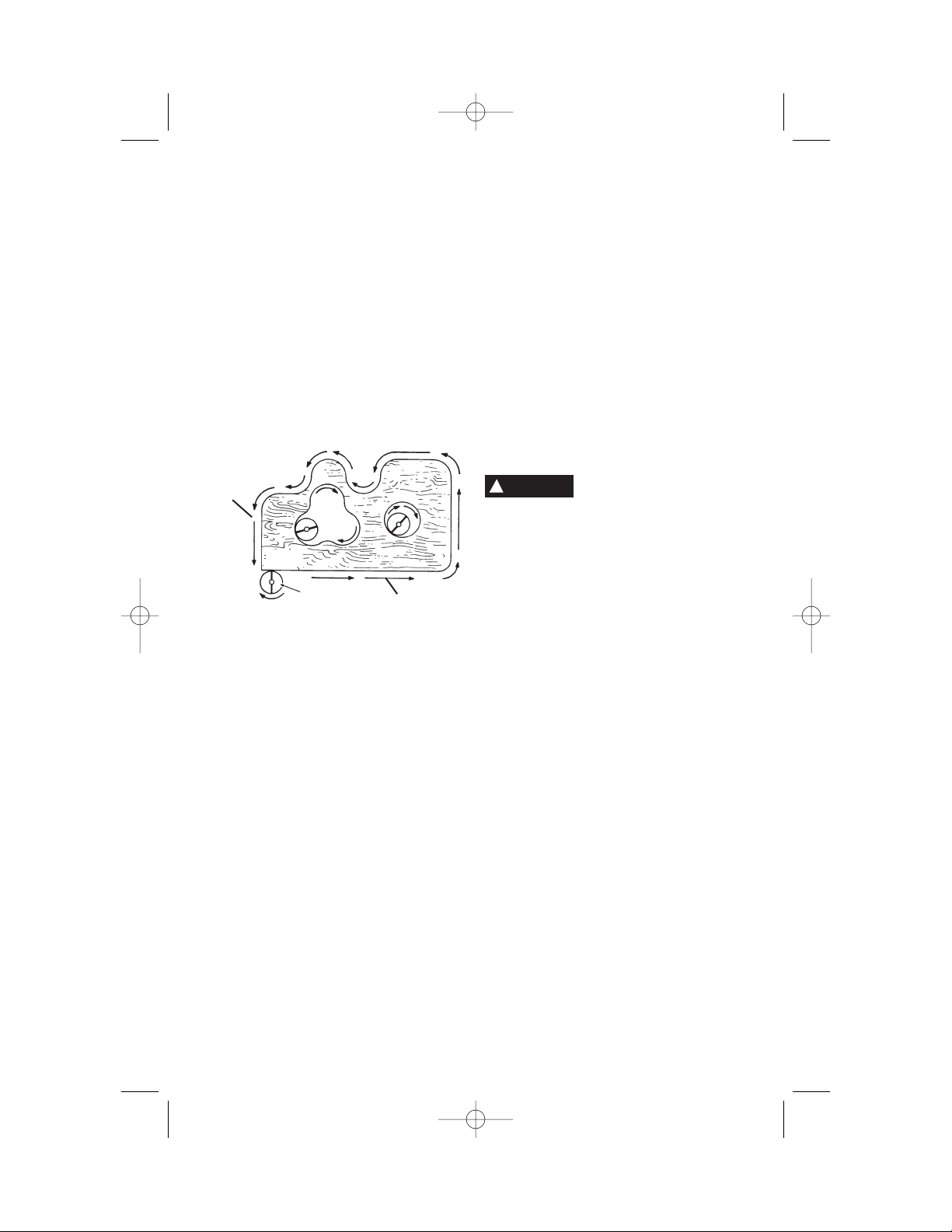
When routing or cutting, the direction of
feed with the bit’s cutting edge into the
material is very important. Always feed
the bit into the material in the same
direction as the cutting edge is exiting
from the material. When viewing the tool
from the top, the bit rotates clockwise. If the
tool is between the workpiece and you body,
then feed the tool to your right. If the
workpiece is between the tool and your body,
then feed the tool to your left. Feeding the
tool in the wrong direction causes the cutting
edge of the bit to climb out of the work and
pull the tool in the direction of this feed.
Never use dull or damaged bits. Sharp
bits must be handled with care. Damaged
bits can snap during use. Dull bits require
more force to push the tool, possibly causing
the bit to break.
Never touch the bit during or immediately
after the use. After use the bit is too hot to
be touched by bare hands.
Never lay the tool down until the motor
has come to a complete standstill. The
spinning bit can grab the surface and pull the
tool out of your control.
Never use bits that have a cutting
diameter greater than the opening in the
base.
Do not use the tool for drilling purposes.
This tool is not intended to be used with drill
bits.
Always use the tool with the depth guide
securely attached and positioned flat
against material being cut. The guide
securely positioned on the material improves
the stability and control of your tool.
Do not use the Zipmate attachment
without the hard auxiliary control handle.
The soft band handle does not provide a
sufficient control for grinding operation.
Some dust created by
power sanding, sawing,
grinding, drilling, and other construction
activities contains chemicals known to
cause cancer, birth defects or other
reproductive harm. Some examples of
these chemicals are:
• Lead from lead-based paints,
• Crystalline silica from bricks and cement
and other masonry products, and
• Arsenic and chromium from chemically-
treated lumber.
Your risk from these exposures varies,
depending on how often you do this type of
work. To reduce your exposure to these
chemicals: work in a well ventilated area, and
work with approved safety equipment, such
as those dust masks that are specially
designed to filter out microscopic particles.
-4-
!
WARNING
BIT
WORK
DIRECTION OF
FEED
START
HERE
RZ 2610917368 9-04 10/1/04 8:09 AM Page 4
-5-
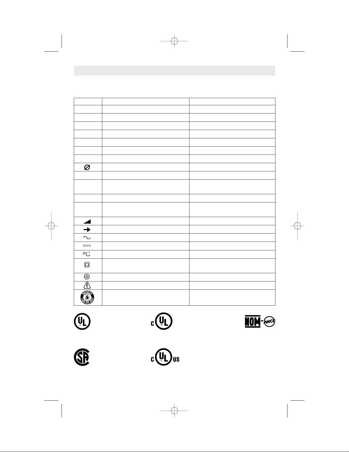
IMPORTANT: Some of the following symbols may be used on your tool. Please study them
and learn their meaning. Proper interpretation of these symbols will allow you to operate the
tool better and safer.
Symbol Name Designation/Explanation
V Volts Voltage (potential)
A Amperes Current
Hz Hertz Frequency (cycles per second)
W Watt Power
kg Kilograms Weight
min Minutes Time
s Seconds Time
Diameter Size of drill bits, grinding wheels, etc.
n
0
No load speed Rotational speed, at no load
.../min Revolutions or reciprocation per minute Revolutions, strokes, surface speed,
orbits etc. per minute
0 Off position Zero speed, zero torque...
1, 2, 3, ... Selector settings Speed, torque or position settings.
I, II, III, Higher number means greater speed
Infinitely variable selector with off Speed is increasing from 0 setting
Arrow Action in the direction of arrow
Alternating current Type or a characteristic of current
Direct current Type or a characteristic of current
Alternating or direct current Type or a characteristic of current
Class II construction Designates Double Insulated
Construction tools.
Earthing terminal Grounding terminal
Warning symbol Alerts user to warning messages
Ni-Cad RBRC seal Designates Ni-Cad battery recycling
program
Symbols
0
This symbol designates
that this tool is listed by
Underwriters Laboratories.
This symbol designates
that this tool is listed by
the Canadian Standards
Association.
This symbol designates
that this tool is listed to
Canadian Standards by
Underwriters Laboratories.
This symbol
designates
that
this tool
complies
to NOM
Mexican
Standards.
This symbol designates that
this tool is listed by
Underwriters Laboratories,
and listed to Canadian
Standards by Underwriters
Laboratories.
RZ 2610917368 9-04 10/1/04 8:09 AM Page 5
-6-
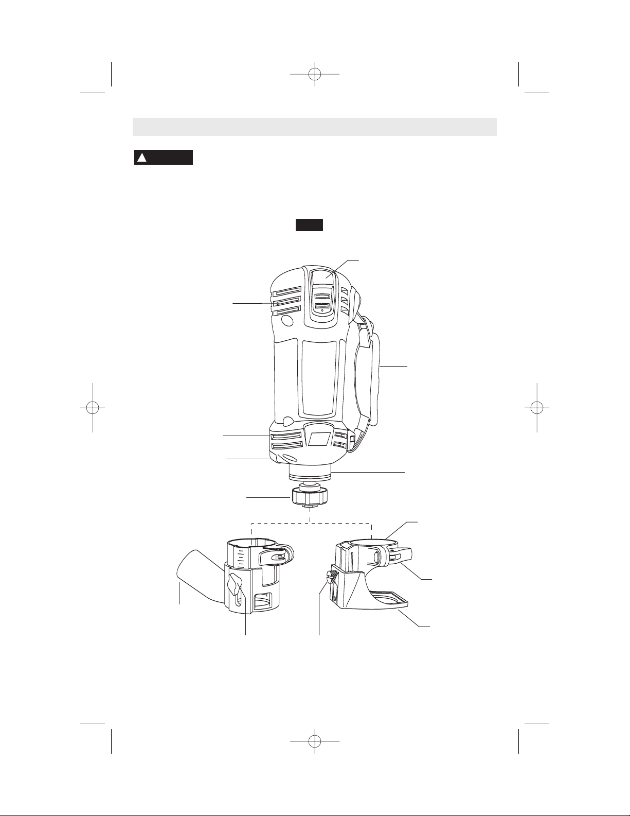
Functional Description and Specifications
Disconnect the plug from the power source before making any
assembly, adjustments or changing accessories. Such preventive safety
measures reduce the risk of starting the tool accidentally.
!
WARNING
NOTE: For tool specifications refer to nameplate on your tool.
DEPTH
GUIDE
DUST HOOD
(Not included,
available as accessory)
SHAFT LOCK
DEPTH GUIDE
BRACKET
LOCK LEVER
INTAKE
AIR VENTS
BUMP-OFF SLIDE
"ON/OFF" SWITCH
SOFT BAND
HANDLE
KEYLESS
CHUCK/COLLET NUT
EXHAUST
AIR VENTS
DEPTH GUIDE
LOCKING
SCREW
COLLAR
FIG. 1
DEPTH GUIDE
LOCKING
KNOB
Spiral Saw™
RZ 2610917368 9-04 10/1/04 8:09 AM Page 6
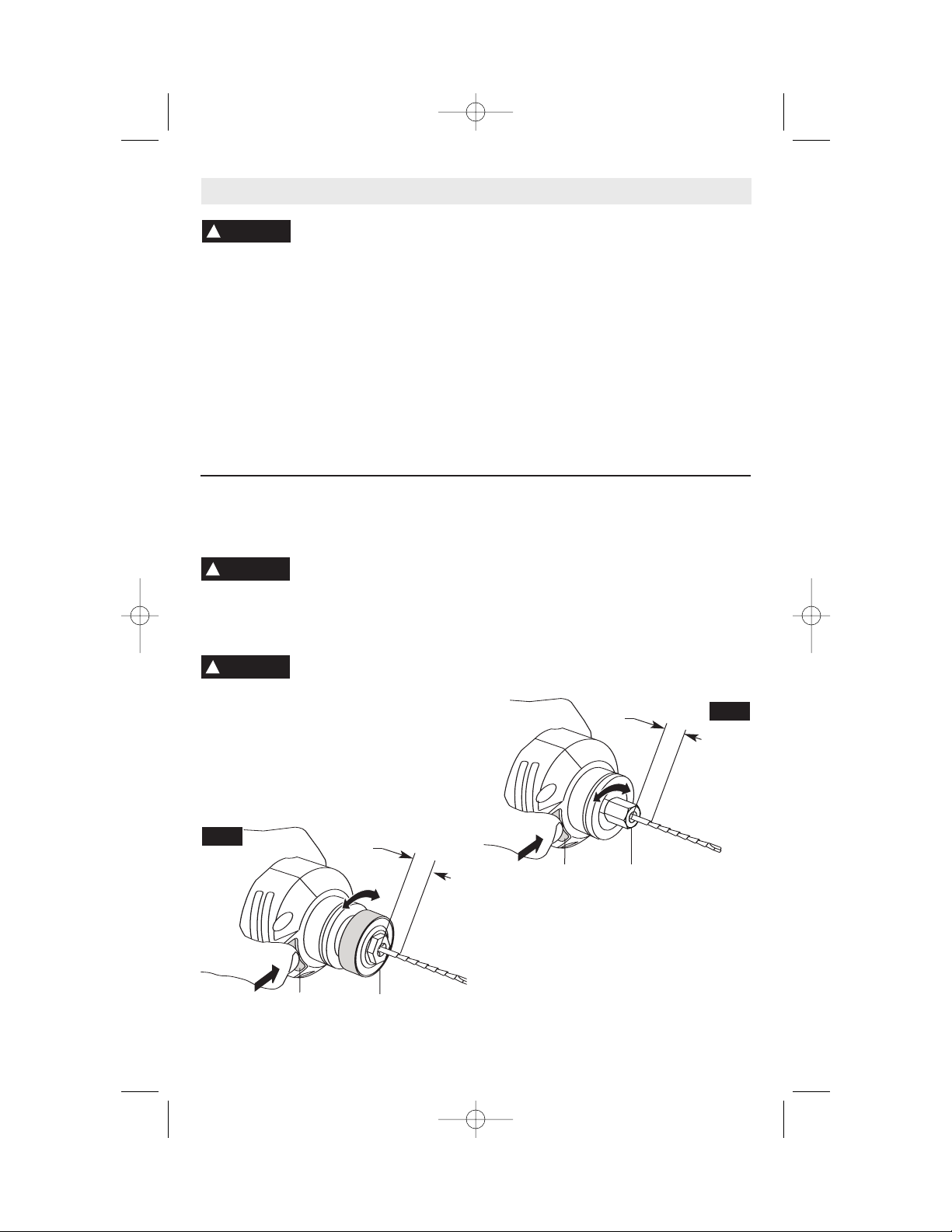
INSTALLING BITS (Keyless models)
The bits are held by a keyless collet system
designed specifically for spiral saw bits with
1/8" (.125"), 1/4" (.250") or 5/32" (.156") shanks.
The bit flutes are sharp and
should be handled with
caution.
Depress and hold the shaft-lock in and rotate
the keyless chuck and shaft until the shaft-
lock engages and holds the shaft.
To prevent damage to tool.
Never use the shaft lock as a
braking devise to stop the tool from rotating.
Rotate the keyless chuck (counter-clockwise)
(Fig. 5). Remove the old bit (if there is one)
insert the new bit as far in as possible, but
not so far that the bit flutes engage the jaws
of the chuck (leave approximately 1/8" of
shank exposed) Re-engage the shaft-lock
and securely tighten the keyless chuck
(clockwise) by hand.
Note: When using 1/4" & 5/32" bits it may be
necessary to use a wrench on the front of the
keyless chuck to securely tighten the bit.
INSTALLING BITS (Standard models)
The bits are held by a collet system. Use either
the 1/8" (.125"), 1/4" (.250") or 5/32" (.156")
collet depending on the size of the bit shank.
Depress and hold the shaft-lock in and rotate
the collet nut and shaft until the shaft-lock
engages and holds the shaft.
Use the standard equipment wrench to
loosen nut (counter-clockwise) (Fig. 6).
Remove the old bit (if there is one) insert the
new bit as far in as possible, but not so far
that the bit flutes engage the collet (leave
approximately 1/8" of shank exposed)
Re-engage the shaft-lock and tighten the nut
(clockwise) by hand and then with the
wrench until bit is held securely.
-7-
Disconnect the plug from
the power source before
making any assembly, adjustments or
changing accessories. Such preventive
safety measures reduce the risk of starting
the tool accidentally. Make certain that the
collet nut is securely tightened before turning
the tool on.
REMOVING AND INSTALLING THE
DEPTH GUIDE ASSEMBLY
The depth guide assembly consists of the
depth guide, locking screw and bracket.
In order to remove the depth guide from the
tool, release the locking lever and pull the
entire assembly straight off of the tool. To
reattach the assembly, fully replace the guide
onto the tool collar and lock the clamp lever
(Fig. 1).
REMOVING AND INSTALLING THE
DUST
HOOD ASSEMBLY
(Not included, available as accessory)
The dust hood is sized to accept 35mm
vacuum hoses.
The dust hood assembly consists of the dust
hood, locking knob and bracket.
In order to remove the dust hood assembly
from the tool, release the locking lever and
pull the entire assembly straight off of the
tool. To reattach the assembly, fully replace
the guide onto the tool collar and lock the
clamp lever (Fig. 1).
Assembly
!
WARNING
!
CAUTION
!
WARNING
KEYLESS
CHUCK
SHAFT
LOCK
1/8"
FIG. 2
COLLET
NUT
FIG. 3
SHAFT
LOCK
1/8"
RZ 2610917368 9-04 10/1/04 8:09 AM Page 7
-8-
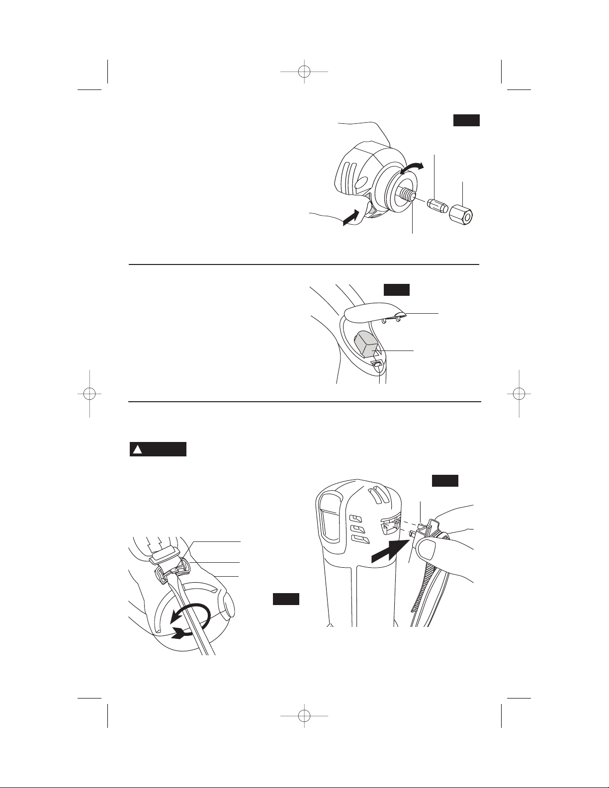
REMOVING AND INSTALLING
THE SOFT BAND HANDLE (Old Style)
Always use auxiliary
handle for maximum
control over torque reaction or kick-back.
Using the tool without the handle could
cause loss of control.
To remove, insert a flat tip screwdriver
between tab and clip as shown, rotate
screwdriver counter-clockwise lifting tab until
clip releases from housing (Fig. 6).
To attach, first insert one side of latch into tool
housing, then firmly push the other latch into
housing while applying pressure in direction
of arrow until clip locks securely into housing
(Fig. 6a).
Repeat this procedure on opposite end of
strap.
CHANGING THE COLLET
The 1/8" collet is used with 1/8" diameter
bits, the 1/4" collet is used with 1/4" diameter
bits and the 5/32" collet is used with 5/32"
diameter bits. To change collets, first
remove the bit. Continue to loosen and
unscrew the collet nut until you can remove it
from the tool. Remove the collet and replace
it with the other (Fig. 4). (Each collet is
double-ended, and either end is acceptable
to use.) By hand, re-tighten the collet nut
around the collet in a clockwise direction.
You are now ready to insert a new bit as
instructed in Installing Bits (Fig. 2 or 3).
COLLET
COLLET
NUT
OUTPUT SHAFT
FIG. 4
TAB
CLIP
HOUSING
FIG. 6
FIG. 6a
LATCH
CLIP
!
WARNING
REMOVING AND INSTALLING THE HARD
AUXILIARY CONTROL HANDLE
Turn the tool OFF and unplug it. Firmly
grasp the tool. Lift open handle release
button cover, depress release button and
remove handle (Fig. 5).
Gently engage the two (2) front latches on
handle into the tool and push handle until it
snaps securely into place.
HANDLE
RELEASE
BUTTON
COVER
HANDLE
RELEASE
BUTTON
FIG. 5
RZ 2610917368 9-04 10/1/04 8:09 AM Page 8
-9-
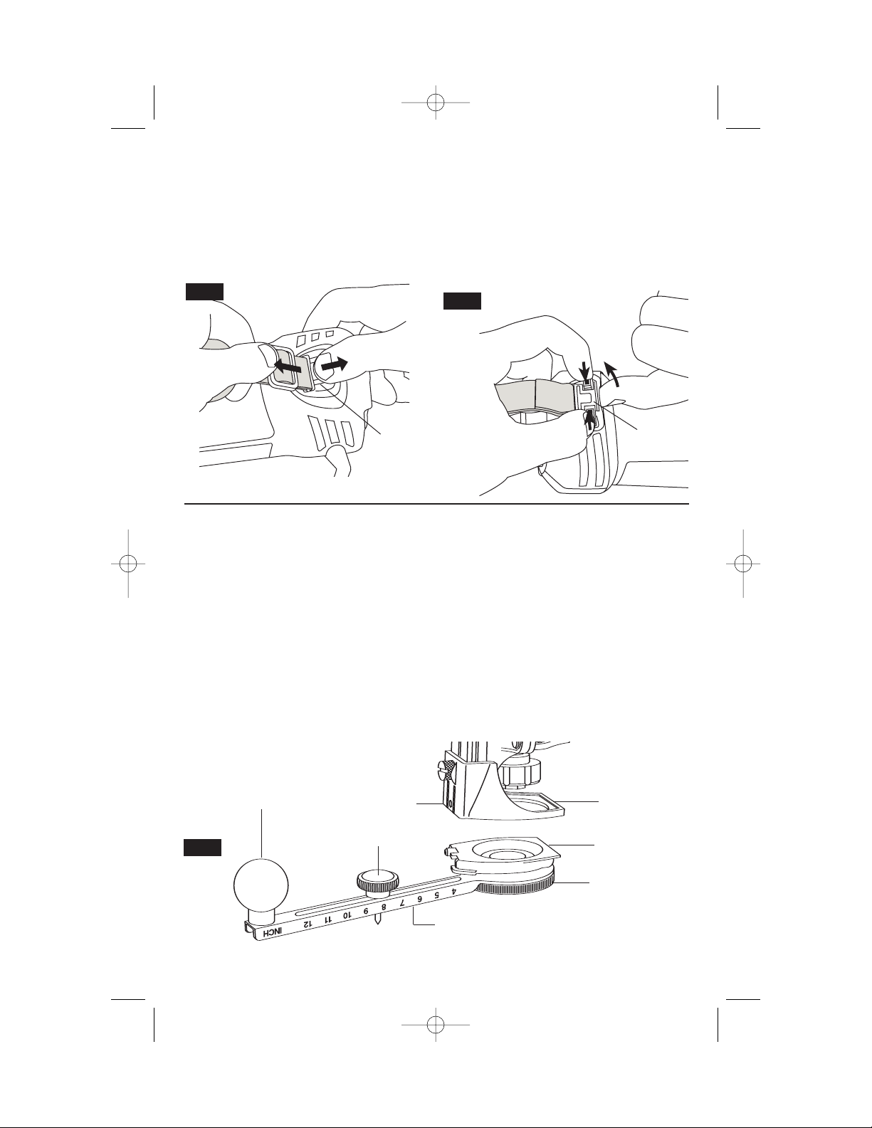
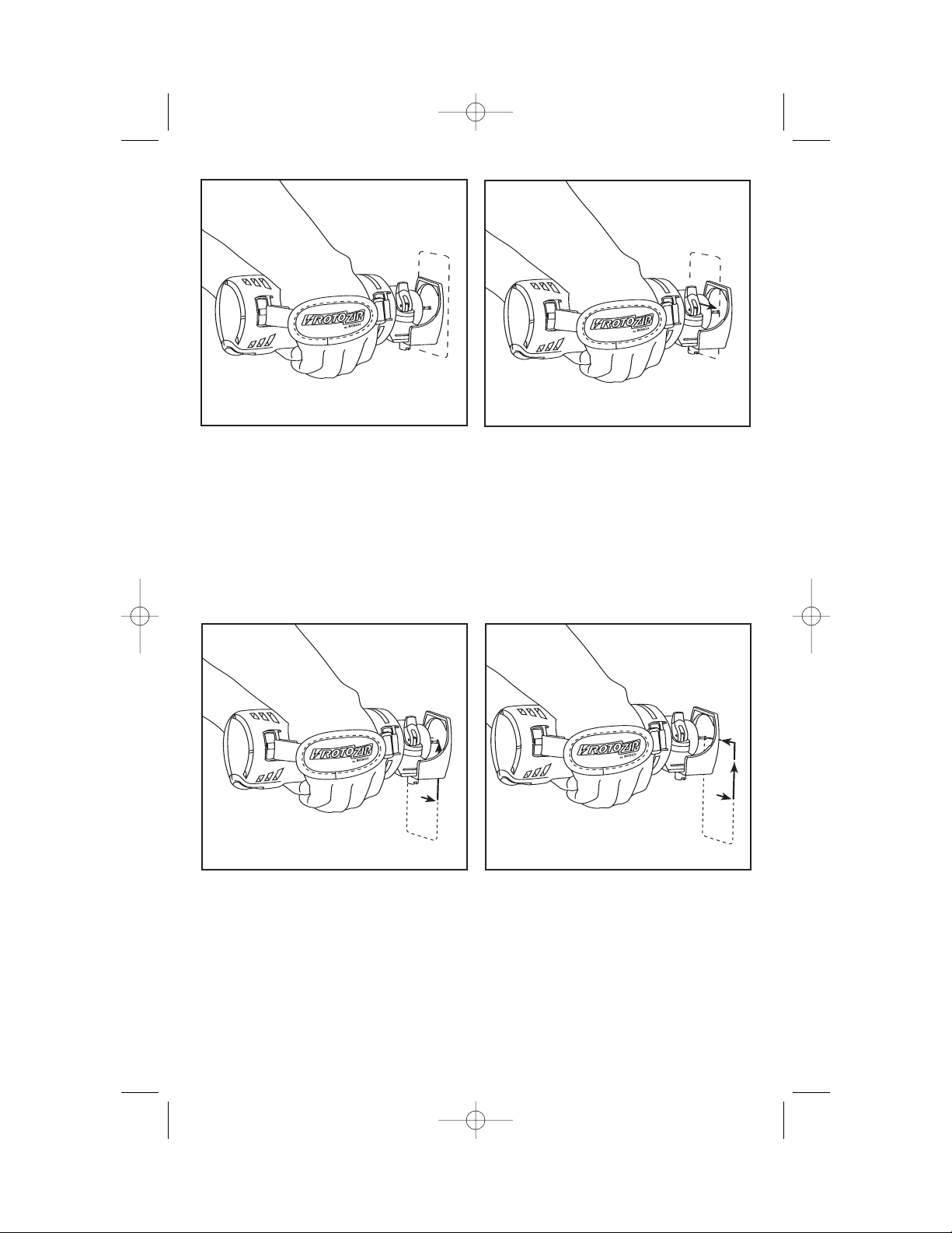
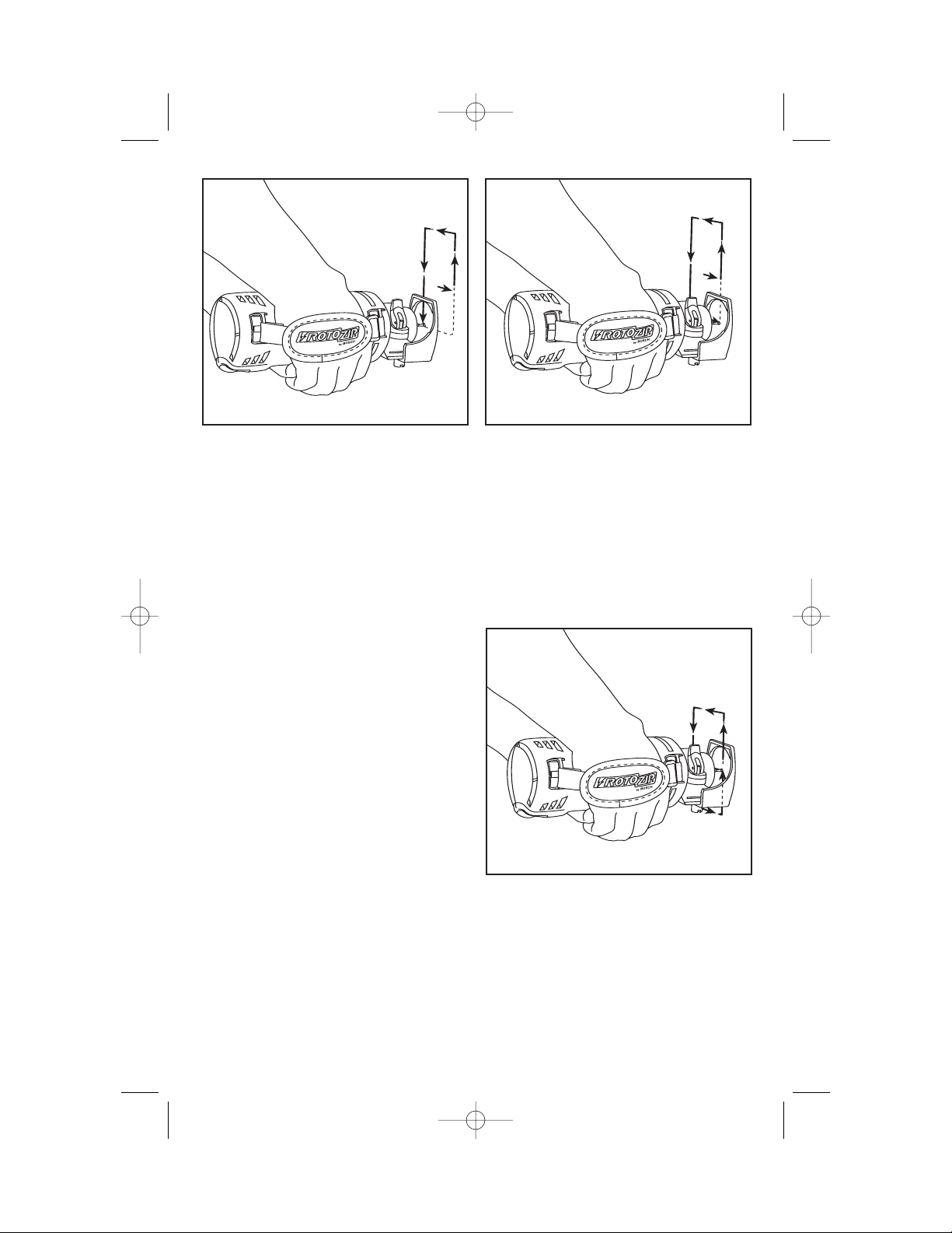
REMOVING AND INSTALLING
THE SOFT HANDLE (New Style)
1 Depress and hold top clip release (Fig. 7).
2 Pull strap away from tool (Fig. 7).
While top clip hook release is depressed, pull
handle strap straight away from tool (Fig. 7).
3 Squeeze from each side and hold both
bottom clip releases (Fig. 8).
4 Lift the back of the clip up and away from
tool (Fig. 8).
While depressing both bottom clip release
tabs, lift the back of the clip away from the
tool (Fig.8).
FIG. 7
TOP CLIP
FIG. 8
BOTTOM
CLIP
ATTACHING CIRCLE CUTTING GUIDE
(Not included, available as accessory)
Your tool is equipped with a circle cutting
guide that can easily be attached directly to
the depth guide, or the optional dust hood
accessory.
1. To attach, position adapter plate and circle
guide as shown and snap into depth guide or
dust hood as shown (Fig. 9).
2. To remove, simply lift tab on depth guide
and remove circle guide and adapter plate.
This attachment allows you to cut perfect
circles from 3.5 to 12” in diameter using your
Bosch power tool.
Loosen pivot knob and slide to desired
diameter of hole to be cut. Line up knob with
diameter size of circle you wish to cut.
For English (IN), use the scale on the side of
the metal rule. For metric (CM) use the scale
the opposite side of the metal rule.
Start cutting in a clockwise direction using
consistent moderate pressure. If you need to
reposition your hands, back tool off work
slightly, in a counter clockwise direction. Re-
start cutting in a clockwise direction.
Continue cutting your circle until you have
cut the complete shape, and turn off tool.
ADAPTER
PLATE
DEPTH
GUIDE
CIRCLE
CUTTING
GUIDE
PIVOT KNOB
ROUND
KNOB
METAL RULE
FIG. 9
TAB
RZ 2610917368 9-04 10/1/04 8:09 AM Page 9
MAKE A FEW PRACTICE CUTS
After installing the Zip Bit into the tool and
adjusting your depth guide, you should make
a few practice cuts with the tool before
attempting an actual job.
A few exercises will give you the necessary
practice to make clean, professional cuts.
Step 1
Make certain that the collet nut is securely
tightened before turning the tool on.
Step 2
Hold the tool firmly and turn the tool ON to
your desired speed.
IMPORTANT USER TIP
Step 3
While holding the tool firmly, insert the Zip Bit
into the material at a 45° angle (Fig. 12).
Step 4
Slowly bring it to a 90° angle to begin the cut
(Fig. 13). The base guide should be flush to
the material surface. For all materials
(EXCEPT cutting around outlet boxes in
drywall), steer the tool in a clockwise
direction with slow, steady pressure to make
the cut.
Step 5
After completing your cut, turn off the tool
and carefully remove it from the material.
Do not attempt to use this tool to make cut-
outs around any fixture or opening which has
live electrical wires, or any wall which may
have live electrical wiring behind it, as the Zip
Bit could conduct current to the tool, creating
an electrocution hazard for the operator.
Shut off breakers or remove fuses to
disconnect the circuit. Always hold the tool
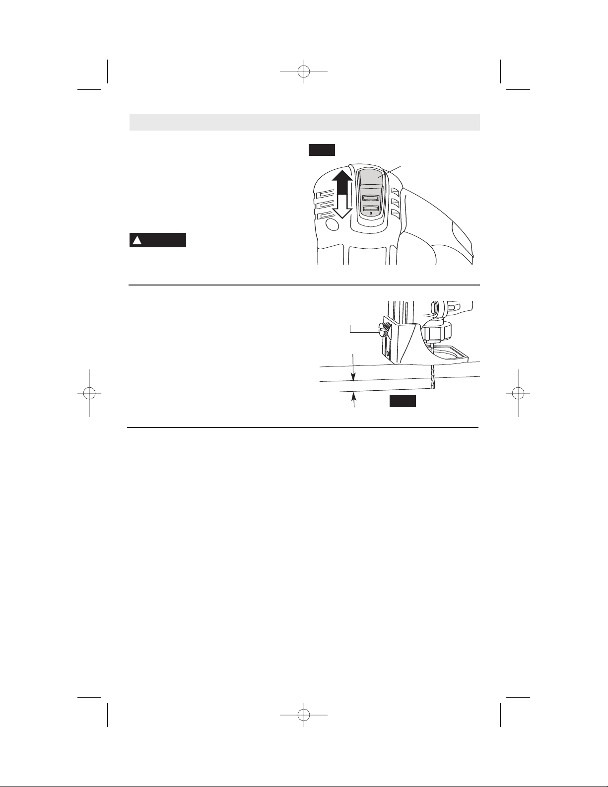
DEPTH GUIDE ADJUSTMENT
Use the depth guide to adjust the depth of
cut. Using the end of the standard wrench,
loosen (counter clockwise) the screw enough
to enable the depth guide to slide up or down
to the desired depth of cut (about 1/8"
greater than material thickness) and
retighten the locking screw (clockwise)
(Fig. 11).
1/8"
DEPTH GUIDE
LOCKING
SCREW
FIG. 11
-10-
Operating Instructions
BUMP-OFF SLIDE "ON/OFF" SWITCH
This tool is switched "ON" by the slide switch
located on the front of the motor housing
(Fig. 10).
TO TURN THE TOOL "ON" slide the switch
button up.
TO TURN THE TOOL "OFF" slide the switch
button down or "0" position.
Hold the tool with both
hands while starting, since
torque from the motor can cause the tool to
twist.
!
WARNING
0
1
BUMP-OFF SLIDE
"ON/OFF" SWITCH
FIG. 10
RZ 2610917368 9-04 10/1/04 8:09 AM Page 10
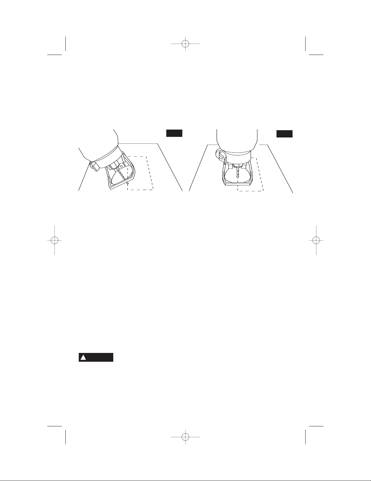
FIG. 12
FIG. 13
-11-
by its thermoplastic housing, and always
wear eye protection when operating a Spiral
Saw power tool.
NOTE: Because of the rotating cutting
action of the Zip Bit, there will be a slight pull
when cutting. The slower you cut, the more
control you have. Excessive pressure or fast
cutting will cause excessive heat and may
shorten the life of the Zip Bit.
NOTE: When cutting on a vertical surface,
avoid ending your cut at the bottom of the
hole. If possible, start and end your cut at
the top so the scrap part will not drop onto
the rotating Zip Bit. Turn the tool off and
remove it from the material.
MAKING DRYWALL CUT OUTS
After assembling the bit into the tool as
described earlier, it will be necessary to
review the instructions provided below and
make some practice cut-outs with this tool
before attempting an actual job. The best
method is to take some scrap pieces and nail
or screw them in place over wall studs which
have an electrical box or other feature in
place. A few such exercises will give you the
necessary practice to make clean,
professional cutouts around whatever is
behind the drywall you are installing.
Do not attempt to use this
tool to make cut-outs
around any fixture or opening which has
live electrical wires, or on any wall which
may have live electrical wiring behind it,
as the bit could conduct current to the
tool, creating an electrocution hazard for
the operator. Shut off breakers or remove
fuses to disconnect the circuit. Always hold
the tool by its thermoplastic housing, and
always wear eye protection when operating
this device.
Step 1: Be certain that the box or fixture
which requires a cut-out is firmly mounted
and all wires or other obstructions around the
opening are pushed back out of the way. The
drywall cut-out bit uses the outer edge of the
box or fixture as a guide, so it is important
that there is nothing in the way which can
prevent it from guiding completely around the
opening. For the purposes of this instruction
manual, the procedure discussed will be to
make a cut-out around a standard 2 1/8" x 3
3/4" electrical box.
ILLUSTRATED INSTRUCTIONS FOR PERFECT OUTLET
OPENINGS IN DRYWALL
The following procedure will illustrate cutting out a standard 2 1/8" X 3 3/4" electrical box.
!
WARNING
RZ 2610917368 9-04 10/1/04 8:09 AM Page 11
Step 4
While keeping the Zip Bit in contact with the
outside of the box move the tool counter
clockwise while applying light inward and
upward pressure until you feel and hear it
come to the corner. As you round the corner
apply light pressure left and downward.
Step 5
While moving slowly and continuously along
the top contour you will feel the Zip Bit come
to the next corner. Round the corner and
apply light down and inward pressure until
the bottom corner is reached.
-12-
Step 2
Slide switch to turn the tool on. While holding
the Spiral Saw power tool firmly with both
hands plunge the Zip Bit through the mark
you made. Then guide the Zip Bit to the right
until you feel and hear the Zip Bit touch the
inside edge of the box.
Step 3
Pull the Zip Bit out far enough to slip it over
the edge of the box so it is now against the
outside of the box.
RZ 2610917368 9-04 10/1/04 8:09 AM Page 12
-13-
Step 6
Move the Zip Bit right and upward maintaining
light continuous pressure toward the box.
Step 7
Round the right bottom corner and begin
moving the bit upward while applying light
pressure left toward the box until you meet
initial upward cut. Push Spiral Saw power tool
switch to off.
Step 8
The completed box, executed quickly, neatly
and in a fraction of the time taken by other
methods.
These step-by-step instructions are
generalized to acquaint you with the Spiral
Saw power tool operation. After some
practice, you may develop a motion
technique with which you are more
comfortable. However, you must always
begin the cut somewhat centrally, and MOVE
THE SPIRAL SAW POWER TOOL ONLY
COUNTERCLOCKWISE to take advantage
of the “hugging” action of the rotating Zip Bit
along the contours of the template.
Remember to use a smooth continuous
motion.
RZ 2610917368 9-04 10/1/04 8:09 AM Page 13
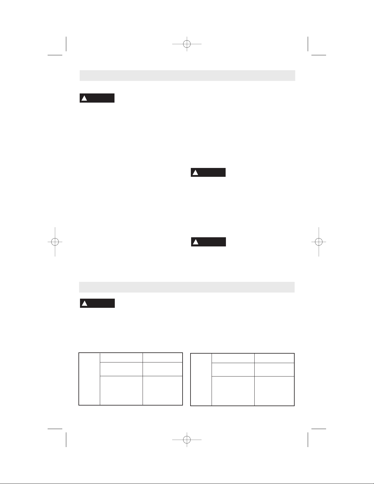
If an extension cord is
necessary, a cord with
adequate size conductors that is capable
of carrying the current necessary for your
tool must be used. This will prevent
excessive voltage drop, loss of power or
overheating. Grounded tools must use 3-
wire extension cords that have 3-prong plugs
and receptacles.
NOTE: The smaller the gauge number, the
heavier the cord.
!
WARNING
Tool’s
Ampere
Rating
Cord Size in A.W.G.
Wire Sizes in mm
2
3-6
6-8
8-10
10-12
12-16
18 16 16 14 0.75 0.75 1.5 2.5
18 16 14 12 0.75 1.0 2.5 4.0
18 16 14 12 0.75 1.0 2.5 4.0
16 16 14 12 1.0 2.5 4.0 —
14 12 — — — — — —
25 50 100 150 15 30 60 120
Cord Length in Feet Cord Length in Meters
Extension Cords
Tool’s
Ampere
Rating
Cord Size in A.W.G.
Wire Sizes in mm
2
3-6
6-8
8-10
10-12
12-16
16 14 1.5 2.5
14 12 2.5 4.0
14 12 2.5 4.0
14 12 4.0 —
—— ——
50 100 30 60
Cord Length in Feet Cord Length in Meters
-14-
Service
Preventive maintenance
performed by unauthorized
personnel may result in misplacing of
internal wires and components which
could cause serious hazard. We
recommend that all tool service be performed
by a Bosch Factory Service Center or Autho-
rized Bosch Service Station.
TOOL LUBRICATION
Your Bosch tool has been properly lubricated
and is ready to use. It is recommended that
tools with gears be regreased with a special
gear lubricant at every brush change.
CHUCK LUBRICATION
The wrenchless chuck has been properly
lubricated and is ready to use. If the chuck's
jaws begin to stick during use, the chuck
requires lubrication. To lubricate the chuck,
first remove debris from the inside of the
chuck with compressed air. Apply a pea-
sized amount of general-purpose grease to
the sides of the jaws, and adjust the chuck
through its full range of motion to distribute
the grease.
CARBON BRUSHES
The brushes and commutator in your tool
have been engineered for many hours of
dependable service. To maintain peak
efficiency of the motor, we recommend every
two to six months the brushes be examined.
Only genuine Bosch replacement brushes
specially designed for your tool should be
used.
BEARINGS
After about 300-400 hours of operation, or at
every second brush change, the bearings
should be replaced at Bosch Factory Service
Center or Authorized Bosch Service Station.
Bearings which become noisy (due to heavy
load or very abrasive material cutting) should
be replaced at once to avoid overheating or
motor failure.
Cleaning
To avoid accidents always
disconnect the tool from
the power supply before cleaning or
performing any maintenance. The tool may
be cleaned most effectively with compressed
dry air. Always wear safety goggles when
cleaning tools with compressed air.
Ventilation openings and switch levers must
be kept clean and free of foreign matter. Do
not attempt to clean by inserting pointed
objects through openings.
Certain cleaning agents
and solvents damage
plastic parts. Some of these are: gasoline,
carbon tetrachloride, chlorinated cleaning
solvents, ammonia and household
detergents that contain ammonia.
!
WARNING
!
WARNING
Maintenance
!
CAUTION
RECOMMENDED SIZES OF EXTENSION CORDS
120 VOLT ALTERNATING CURRENT TOOLS
RECOMMENDED SIZES OF EXTENSION CORDS
120 VOLT ALTERNATING CURRENT TOOLS
(Model RZ25 only)
RZ 2610917368 9-04 10/1/04 8:09 AM Page 14
 Loading...