


 Loading...
Plena Mixer Amplifier
Installation and User Instructions
en PLE-2MA120-EU
PLE-2MA240-EU

Plena Mixer Amplifier | Installation and User Instructions | Important safeguards |
en | 2 |
|
|
Important safeguards
Before installing or operating this product, always read the Safety Instructions, which are available as a separate document (9922 141 7014x). These instructions are supplied together with all equipment that can be connected to the mains.
Thank you for choosing a Bosch Security Systems product!
Bosch Security Systems | 2007-10 | PLE-2MA120-EU, PLE-2MA240-EU en

Plena Mixer Amplifier | Installation and User Instructions | Table of contents |
en | 3 |
|
|
Table of contents
|
Important safeguards ................................................................................................................................................... |
2 |
||
|
Table of contents ........................................................................................................................................................... |
3 |
||
1. |
Introduction .................................................................................................................................................................... |
5 |
||
1.1 |
Purpose ..................................................................................................................................................................................... |
5 |
||
1.2 |
Digital document ..................................................................................................................................................................... |
5 |
||
1.3 |
Intended audience .................................................................................................................................................................. |
5 |
||
1.4 |
Related documentation .......................................................................................................................................................... |
5 |
||
1.5 |
Alerts .......................................................................................................................................................................................... |
5 |
||
1.6 |
Icons ........................................................................................................................................................................................... |
5 |
||
|
1.6.1 |
Note icons ........................................................................................................................................................................... |
5 |
|
|
1.6.2 Caution, Warning, and Danger icons ........................................................................................................................... |
5 |
||
1.7 |
Conversion tables ................................................................................................................................................................... |
6 |
||
2. |
Description ..................................................................................................................................................................... |
7 |
||
2.1 |
The Plena product range ....................................................................................................................................................... |
7 |
||
2.2 |
Contents of box ....................................................................................................................................................................... |
7 |
||
2.3 |
The Plena Mixer Amplifier ...................................................................................................................................................... |
7 |
||
2.4 |
Controls, connectors and indicators .................................................................................................................................. |
9 |
||
|
2.4.1 |
Front panel .......................................................................................................................................................................... |
9 |
|
|
2.4.2 Plena PLE-WP2Z3S wall panel ..................................................................................................................................... |
9 |
||
|
2.4.3 |
Rear panel ........................................................................................................................................................................ |
10 |
|
3. |
Installation ................................................................................................................................................................... |
13 |
||
3.1 |
Unpack unit ............................................................................................................................................................................ |
13 |
||
3.2 |
Install unit in rack (optional) ............................................................................................................................................... |
13 |
||
3.3 |
Check settings/connections .............................................................................................................................................. |
13 |
||
3.4 |
Connect unit to mains ......................................................................................................................................................... |
13 |
||
4. |
Connections and settings ........................................................................................................................................ |
15 |
||
4.1 |
Connecting inputs ................................................................................................................................................................ |
15 |
||
|
4.1.1 |
DC supply (battery) ........................................................................................................................................................ |
15 |
|
|
4.1.2 Priority microphone (input 1) ....................................................................................................................................... |
16 |
||
|
4.1.3 Secondary microphone (input 2) ................................................................................................................................ |
17 |
||
|
4.1.4 Additional microphones (inputs 3 through 6) .......................................................................................................... |
17 |
||
|
4.1.5 |
Emergency inputs ........................................................................................................................................................... |
18 |
|
|
4.1.6 |
Music source inputs ....................................................................................................................................................... |
20 |
|
4.2 |
Connecting outputs ............................................................................................................................................................. |
21 |
||
|
4.2.1 Zone 1 and 2 ................................................................................................................................................................... |
21 |
||
|
4.2.2 |
Call only ............................................................................................................................................................................ |
21 |
|
|
4.2.3 |
Music only ........................................................................................................................................................................ |
21 |
|
|
4.2.4 Line out/ loop through ................................................................................................................................................... |
21 |
||
|
4.2.5 |
Connecting speakers ..................................................................................................................................................... |
22 |
|
4.3 |
Unit settings .......................................................................................................................................................................... |
23 |
||
|
4.3.1 |
Rear panel settings ........................................................................................................................................................ |
23 |
|
|
4.3.2 Pin settings and labelling .............................................................................................................................................. |
25 |
||
Bosch Security Systems | 2007-10 | PLE-2MA120-EU, PLE-2MA240-EU en

Plena Mixer Amplifier | Installation and User Instructions | Table of contents |
en | 4 |
|||
|
|
|
||
5. |
Operation ..................................................................................................................................................................... |
27 |
||
5.1 |
Switch on and off ................................................................................................................................................................. |
27 |
||
|
5.1.1 |
Switch on ......................................................................................................................................................................... |
27 |
|
|
5.1.2 |
Switch off ......................................................................................................................................................................... |
27 |
|
5.2 |
Microphone/line controls .................................................................................................................................................... |
28 |
||
5.3 |
Music controls ....................................................................................................................................................................... |
28 |
||
|
5.3.1 |
Source selection ............................................................................................................................................................. |
28 |
|
|
5.3.2 |
Volume control ................................................................................................................................................................ |
28 |
|
5.4 |
Tone control .......................................................................................................................................................................... |
28 |
||
|
5.4.1 |
Introduction ...................................................................................................................................................................... |
28 |
|
|
5.4.2 |
Microphone/line tone control ....................................................................................................................................... |
28 |
|
|
5.4.3 |
Music tone control .......................................................................................................................................................... |
28 |
|
5.5 |
Output controls ..................................................................................................................................................................... |
29 |
||
|
5.5.1 |
Zone selection ................................................................................................................................................................. |
29 |
|
|
5.5.2 |
Master volume control ................................................................................................................................................... |
29 |
|
6. |
Technical data ............................................................................................................................................................. |
31 |
||
6.1 |
Electrical ................................................................................................................................................................................. |
31 |
||
|
6.1.1 |
Mains power supply ....................................................................................................................................................... |
31 |
|
|
6.1.2 |
Battery power supply ..................................................................................................................................................... |
31 |
|
|
6.1.3 |
Power consumption ....................................................................................................................................................... |
31 |
|
|
6.1.4 |
Performance .................................................................................................................................................................... |
31 |
|
|
6.1.5 |
RJ-45 input 2 x ................................................................................................................................................................ |
31 |
|
|
6.1.6 |
Mic/line input 6 x ............................................................................................................................................................. |
31 |
|
|
6.1.7 |
Music inputs 3x ............................................................................................................................................................... |
32 |
|
|
6.1.8 |
Emergency / telephone 1 x .......................................................................................................................................... |
32 |
|
|
6.1.9 |
Loop through insert 1 x ................................................................................................................................................. |
32 |
|
|
6.1.10 |
Master/music output 1 x ............................................................................................................................................... |
32 |
|
|
6.1.11 |
Loudspeaker outputs 100 V* ....................................................................................................................................... |
32 |
|
|
6.1.12 |
Loudspeaker output 8 ohm* ........................................................................................................................................ |
32 |
|
6.2 |
Mechanical ............................................................................................................................................................................. |
32 |
||
6.3 |
Environmental ........................................................................................................................................................................ |
32 |
||
Bosch Security Systems | 2007-10 | PLE-2MA120-EU, PLE-2MA240-EU en
Plena Mixer Amplifier | Installation and User Instructions | Introduction |
en | 5 |
|
|
1 Introduction 1.6 Icons
1.1Purpose
The purpose of these Installation and User Instructions is to provide information required for installing, configuring and operating a Plena Mixer Amplifier.
1.2Digital document
These Installation and User Instructions are also available as a digital document in the Adobe Portable Document Format (PDF).
1.3Intended audience
These Installation and User Instructions are intended for installers and users of a Plena system.
1.6.1Note icons
The icons used in combination with Notes provide extra information about the Note. See the following examples:
Note
General icon for notes.
Note
Consult the indicated source of information.
1.4Related documentation
Safety Instructions (9922 141 1036x).
1.5Alerts
Four types of alerts are used in this manual. The alert type is closely related to the effect that may be caused if it is not observed. These alerts - from least severe effect to most severe effect - are:
•Note
Alert containing additional information. Usually, not observing a note alert does not result in damage to the equipment or personal injuries.
•Caution
The equipment can be damaged if the alert is not observed.
•Warning
Persons can be (severely) injured, or the equipment can be seriously damaged, if the alert is not observed.
•Danger
Not observing the alert can result in death.
1.6.2Caution, Warning, and Danger
icons
The icons used in combination with Caution, Warnings, and Dangers indicate the type of hazard present. See the following examples:
Caution, Warning, Danger
General icon for Cautions, Warnings and
Dangers.
Caution, Warning, Danger
Icon for risk of electric shock.
Caution, Warning, Danger
Icon for risk of electrostatic discharge.
Bosch Security Systems | 2007-10 | PLE-2MA120-EU, PLE-2MA240-EU en

Plena Mixer Amplifier | Installation and User Instructions | Introduction |
en | 6 |
|
|
1.7Conversion tables
In this manual, SI units are used to express lengths, masses, temperatures etc. These can be converted to non-metric units using the following information.
table 1.1: Conversion of units of length
1 in = |
25.4 mm |
1 mm = |
0.03937 in |
1 in = |
2.54 cm |
1 cm = |
0.3937 in |
1 ft = |
0.3048 m |
1 m = |
3.281 ft |
1 mi = |
1.609 km |
1 km = |
0.622 mi |
table 1.2: Conversion of units of mass |
|
||
1 lb = |
0.4536 kg |
1 kg = |
2,2046 lb |
table 1.3: Conversion of units of pressure |
|
||
1 psi = |
68.95 hPa |
1 hPa = |
0.0145 psi |
Note
1 hPa = 1 mbar.
table 1.4: Conversion of units of temperature
° F = |
9 |
. ( ° C + 32) |
° C = |
5 |
. ( ° F |
32) |
|
° F = |
5 |
|
|
° C = |
9 |
|
|
Bosch Security Systems | 2007-10 | PLE-2MA120-EU, PLE-2MA240-EU en

Plena Mixer Amplifier | Installation and User Instructions | Description |
en | 7 |
|
|
2Description
2.1The Plena product range
The Plena Mixer Amplifier is part of the Plena product range. Plena provides public address solutions for places where people gather to work, worship, trade, or relax. It is a family of system elements that are combined to create public address systems tailored for virtually any application
The Plena product range includes:
•mixers
•preamplifiers
•power amplifiers
•a music source unit
•a digital message manager
•a feedback suppressor
•call stations
•an All-in-One system
•a voice alarm system
•a timer
•a charger
•a loop amplifier
The various elements are designed to complement each other thanks to matched acoustical, electrical and mechanical specifications.
2.2Contents of box
The packaging box contains the following contents:
•PLE-2MA120-EU, or PLE-2MA240-EU
•Labels and colored pins for indicating favorite settings
•Power cord
•Plena Bonus CD
•Mounting brackets (LBC 1901/00)
2.3The Plena Mixer Amplifier
The Plena Mixer Amplifier is a high performance, professional public address unit for mixing up to six separate microphone/line signals, and any one of three separate music signals. For a schematic overview of the Plena Mixer Amplifier, see figure 2.1 on the next page.
The volume of each microphone/line signal can be individually adjusted to obtain the required mix; the mixed output is controlled via the master volume control and separate high/low tone controls.
The unit is easy to use, and provides a crisp call or clear music. The amplifier also has enhanced features such as ducking level control, priority, labelling, and setting indicators.
All Microphone/line inputs can be switched between microphone level and line level sensitivity. The inputs are balanced but can also be used unbalanced. Phantom power can be selected via a DIP switch to provide power to condenser microphones. Input channels 1 and 2 can take priority over all other microphone and music inputs:
•Input 1 can be activated by contact closure on a PTT (push to talk). A chime can be configured to precede an announcement.
•Input 2 can be switched automatically if a signal is available at the input, for example. if someone speaks into the microphone (VOX activation).
A telephone/100 V emergency input with VOX activation is also provided for easy integration with another PA system or a telephone paging system. It has its own volume control and overrides all other inputs, including the call station and inputs 1 and 2.
The unit also has a line output to add amplifiers for larger systems that require more output power. This output can be switched to music only, for example, so that music on hold can be provided for the telephone system. Loop through input and output connections enable external sound processing equipment (for example, an equalizer or Plena feedback suppressor) to be connected between the preamplifier and the power amplifier stages. A feedback suppressor can ensure feedback-free, clear speech for all microphones.
Users can create custom labels for inputs, music sources, and output zones. These labels can be attached to the special holders at the front of the mixer amplifier. Colored pins can also be inserted at various positions around the volume and tone dial controls to indicate favorite settings for a particular application.
Bosch Security Systems | 2007-10 | PLE-2MA120-EU, PLE-2MA240-EU en

Plena Mixer Amplifier | Installation and User Instructions | Description |
en | 8 |
|
|
An LED meter monitors the master output before the zone selection. This signal is also present on the headphone connector below the output meter. For total reliability and ease of use, a limiter is integrated into the output stage to restrict output if the user applies too much signal.
The unit has 24 VDC backup input with built in
24 VDC battery charger. A separate battery charger is, therefore, not required. The charger charges the battery with a 0.5 A constant current until the battery voltage reaches 27.4 VDC. The charger then switches over to constant voltage charging (also known as float charging).
Note
When using the unit with backup power of 24 V, make sure that the unit is always powered ON. When the unit is switched OFF, the batteries will be drained as this will be regarded as a power source. Consequently the unit will revert to
24 VDC power from the 24 V input
|
|
0 |
Call Only |
|
CALL STATION |
Call Station Control |
|
||
0 |
0 |
|||
|
|
|||
|
|
0 |
Zone 1 |
|
XLR+Ph |
|
|
||
|
|
|
|
Amplifier |
100V |
|
Phantom |
|
|
|
|
|
|
|
Power |
|
8 Ohm |
0 |
I NS |
I NS |
Zone 1 |
|
Out |
In |
|
|
|
Click |
0 |
|
|
suppression |
|
|
|
Bal. input |
|
Zone 2 |
LINE/MIC |
Music only / Line out |
LINE/MIC
 201
201
115V,230V
LINE/MIC
D.C.supply
CUSL
Wall Panel input micro controller
figure 2.1: Schematic overview of the Plena Mixer Amplifier
Bosch Security Systems | 2007-10 | PLE-2MA120-EU, PLE-2MA240-EU en
Plena Mixer Amplifier | Installation and User Instructions | Description |
en | 9 |
|
|
2.4Controls, connectors and indicators
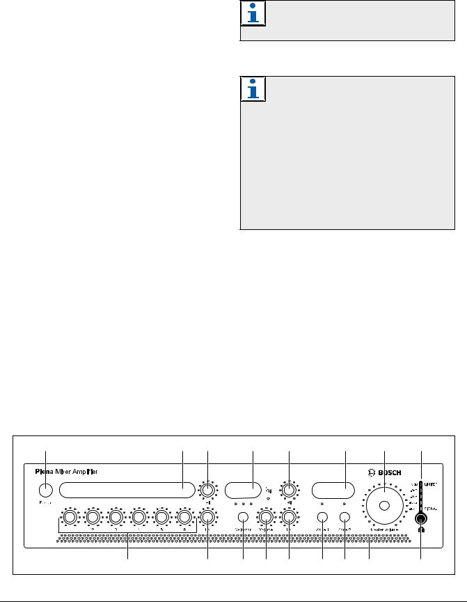
2.4.1Front panel
See figure 2.2 for an overview of the controls and indicators.
1 Power button.
2Label holder for user-defined description of microphone/line inputs - custom labels can be
created by user.
3 Master high tone control for microphone/line inputs. 4 Label holder for user-defined description of music sources - custom labels can be created by user.
5 Master high tone control for music inputs.
6 Label holder for user-defined description of zone names - custom labels can be created by user.
7Master volume control - controls all inputs except emergency and call station.
8 Output level meter (-18 db, 0 db)
9Input level control:
•microphone/line 1
•microphone/line 2
•microphone/line 3
•microphone/line 4
•microphone/line 5
•microphone/line 6
10Master low tone control for microphone/line inputs.
11Music source selector (for music inputs 1, 2, and 3).
12Music source volume control.
13Master low tone control for music inputs.
14Zone 1 selection button.
15Zone 2 selection button
16 Air inlet holes.
Note
Do not obstruct the airflow into the unit.
17 Headphone socket.
Note
Users can create custom labels for the: microphone/line inputs, description of the music sources, and audio output zones 1 and 2. These labels can be attached to the mixer amplifier at position numbers 2, 4, and 6 (see figure 2.2). Colored pins can also be inserted at various positions around the dial controls to indicate the favorite settings for a particular application. For more information on inserting and removing pins, see section 4.3.2.
2.4.2Plena PLE-WP2Z3S wall panel
The optional Plena PLE-WP2Z3S wall panel can be used to remotely control the unit from a maximum of four remote locations. The appearance of the wall panel is matched to the Bosch loudspeaker volume controls.
The zone can be activated or deactivated, and the music source can be easily changed. The status of each zone and music source is indicated by an LED.
A standard CAT 5 cable is used to connect the wall panel to the mixer-amplifier. The maximum distance is 200 m. Please refer to the relevant datasheet for more information.
1 |
2 |
3 |
|
4 |
5 |
|
6 |
7 |
8 |
|
|
|
|
|
|
|
|
|
B |
9 |
|
10 |
11 |
12 |
13 |
14 |
15 |
16 |
17 |
figure 2.2: Front panel
Bosch Security Systems | 2007-10 | PLE-2MA120-EU, PLE-2MA240-EU en

|
Plena Mixer Amplifier | Installation and User Instructions | Description |
|
en | 10 |
||||||
|
|
|
|
|
|
|
|
||
|
2.4.3 Rear panel |
13 |
Tel. emergency/100V input, Euro style pluggable |
||||||
|
See figure 2.3 for an overview of the connectors and |
|
|
screw terminal connector - VOX function. This input |
|||||
|
switches: |
|
|
has highest priority. |
|
|
|||
|
|
|
|
14 |
Call station input, RJ-45 connector - PLE-2CS or |
||||
1 |
Cooling fan. |
|
|
PLE-2CS-MM, chimes are in call station. This input |
|||||
|
|
|
|
|
|
has second highest priority. |
|
|
|
|
|
|
|
15 |
Remote control wall-panel-input, RJ-45 connector. |
||||
|
|
|
|
||||||
|
|
|
Note |
|
|
Wall panel incorporates: BGM source selection, and |
|||
|
|
|
Always allow adequate space at the rear of the |
|
|
zone on/off control. |
|
|
|
|
|
|
unit for ventilation. |
16 |
Telephone emergency/100V input volume control - |
||||
|
|
|
|
|
|
control range -25 dB to 0dB (see number 13). |
|
|
|
|
|
|
|
|
|
|
|
||
2 |
Microphone/line 1 input, XLR connector - DIP |
17 |
Chime volume control for microphone/line input 1 |
||||||
|
|
switch settings for: chime, PTT (push to talk), |
|
|
(see numbers 2 and 3). |
|
|
||
|
|
mic/line, speech filter, and phantom power (see |
18 |
Ducking level control for microphone/line inputs 1 |
|||||
|
|
number 4). Input is wired in parallel with |
|
|
and 2 and call stations. |
|
|
||
|
|
microphone/line 1, Euro style pluggable screw |
19 |
Music input (number 1 disc), 2x RCA/cinch |
|
|
|||
|
|
terminal connector (see number 3). |
|
|
connectors. Stereo, summed mono. |
|
|
||
3 |
Microphone/line 1 input with trigger, Euro style |
20 |
Music input (number 2 radio), 2x RCA/cinch |
|
|
||||
|
|
pluggable screw terminal connector - DIP switch |
|
|
connectors. Stereo, summed mono. |
|
|
||
|
|
settings for: chime, PTT (push to talk), mic/line, |
21 |
Music input (number 3 auxiliary), 2x RCA/cinch |
|||||
|
|
speech filter, and phantom power (see number 4). |
|
|
connectors. Stereo, summed mono. |
|
|
||
|
|
Input is wired in parallel with microphone/line 1, |
22 |
Pre-out, amp in insert, 2x RCA/cinch connector - |
|||||
|
|
XLR connector (see number 2). |
|
|
can be used for EQ or feedback suppressor. |
|
|
||
4 |
DIP switch for microphone/line 1 and microphone/ |
23 |
Master switch for line out or music (see number 24). |
||||||
|
|
line 2 (see numbers 2 and 3, and 5 respectively). |
24 |
Music master output, XLR connector - switch setting |
|||||
5 |
Microphone/line 2 input, XLR connector - DIP |
|
|
for line out, or music only (see number 23). |
|
|
|||
|
|
switch settings for speech filter, mic/line, VOX, and |
25 |
Outputs and 24 VDC in/out: |
|
|
|||
|
|
phantom power (see number 4). |
|
• |
Zone 1 output, Euro style pluggable screw terminal |
||||
6 |
Microphone/line 3 input, XLR connector - DIP |
|
|
connector - 100 V, and 8 Ohm. |
|
|
|||
|
|
switch settings for mic/line, and phantom power |
|
• |
Zone 2 output, Euro style pluggable screw terminal |
||||
|
|
(see number 7). |
|
|
connector - 100 V, and 8 Ohm. |
|
|
||
7 |
DIP switch for microphone/line 3 and microphone/ |
|
• |
Call only, Euro style pluggable screw terminal |
|||||
|
|
line 4 (see numbers 6 and 8 respectively). |
|
|
connector 100 V. |
|
|
||
8 |
Microphone/line 4 input, XLR connector - DIP |
|
• |
24 VDC in/out: |
|
|
|||
|
|
switch settings for mic/line, and phantom power |
|
|
• Input: 24 VDC backup power. |
|
|
||
|
|
(see number 7). |
|
|
• Output: built in charger, maximum 0.5 A. |
|
|
||
9 |
Microphone/line 5 input, XLR connector - DIP |
|
|
regulated output current. If battery charging is |
|||||
|
|
switch settings for mic/line, and phantom power |
|
|
not required, output can be used for volume |
||||
|
|
(see number 10). |
|
|
overrides or other purposes. |
|
|
||
10 |
DIP switch for microphone/line 5 and microphone/ |
26 |
Mains fuse. |
|
|
||||
|
|
line 6 (see numbers 9 and 11 respectively). |
27 |
Earth connection screw. |
|
|
|||
11 |
Microphone/line 6 input, XLR connector - DIP |
|
|
|
|
|
|
||
|
|
switch settings for mic/line, and phantom power |
|
|
|
|
|
|
|
|
|
(see number 10). |
|
|
Note |
|
|
||
12 |
Mains voltage switch, C13 - 115/230 |
|
|
The unit must be earthed. |
|
|
|||
|
|
VAC 50/60 Hz. |
|
|
|
|
|
|
|
|
|
28 |
Mains connector (3-pole). |
|
|
||||
|
|
|
|
|
|
||||
Bosch Security Systems | 2007-10 | PLE-2MA120-EU, PLE-2MA240-EU en
Plena Mixer Amplifier | Installation and User Instructions | Description |
en | 11 |
|
|
1 |
2 |
3 |
4 |
|
5 |
|
6 |
7 |
8 |
9 |
10 |
11 |
12 |
13 |
|
14 15 16 |
17 |
18 |
19 |
20 |
21 |
22 23 |
24 |
25 |
|
26 27 28 |
|
figure 2.3: Rear panel
Bosch Security Systems | 2007-10 | PLE-2MA120-EU, PLE-2MA240-EU en
Loading...