


 Loading...
*9000443032* 9000443032 940429
Ø Montageanleitung
Ú Installation instructions Þ Notice de montage
â Istruzioni per il montaggio é Installatievoorschrift
× Monteringsvejledning ó Monteringsanvisning
ê Monteringsveiledning Ý Asennusohje
Û Instrucciones de montaje ì Instruções de montagem
Ù Οδηγίες εγκατάστασης
Ö Montážní návod ë Instrukcja montażu
î Инструкция по монтажу
ô Montaj kılavuzu
PLQ
|
|
|
|
|
& |
|
|
|
|
|
|
|
|
|
|
% |
|
|
|
|
|
|

PLQ

PLQ |
|
|
|
PD[ |
|
|
|
|
|
|
|
|
% |
|
|
|
|
|
|
' |
|
|
|
( |
|
PLQ |
|
PLQ |
PLQ
PLQ
 PLQ
PLQ
de
Ø
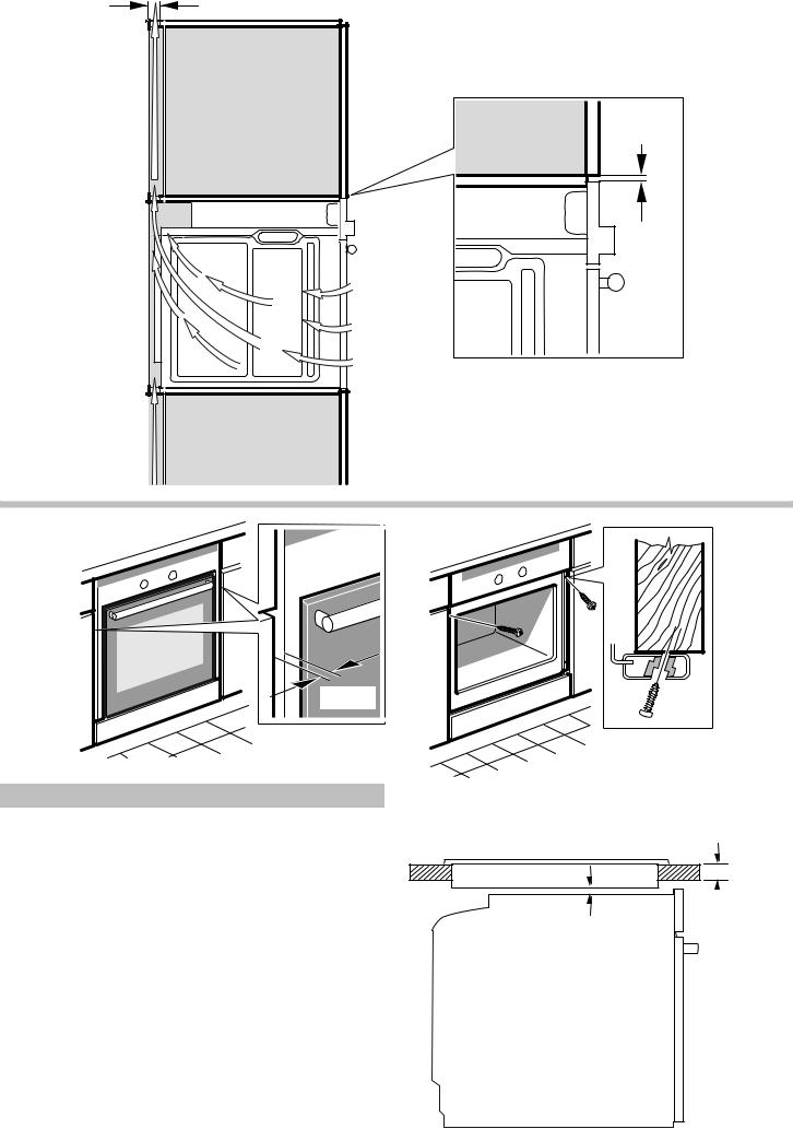
Möbel vorbereiten -Bild 1
■Nur ein fachgerechter Einbau nach dieser Montageanweisung garantiert einen sicheren Gebrauch.Bei Schäden durch falschen Einbau haftet der Monteur.
■Einbaumöbel müssen bis 90 °C temeperaturbeständig sein, angrenzende Möbelfronten bis 70 °C.
■Alle Ausschnittarbeiten an Möbel und Arbeitsplatte vor dem Einsetzen der Geräte durchführen. Späne entfernen, dieFunktion von elektrischen Bauteilen kann beeinträchtigt werden.
■Vorsicht beim Einbau! Teile, die während der Montage zugänglich sind, können scharfkantig sein. Zur Vermeidung von Schnittverletzungen Schutzhandschuhe tragen
■Die Geräte-Anschlussdose muss im Bereich der schraffierten Fläche B oder außerhalb des Einbauraumes liegen.
■Zwischen Gerät und angrenzenden Möbelfronten ist ein Luftspalt von 5 mm erforderlich.
■Nicht befestigte Möbel mit einem handelsüblichen Winkel C an der Wand befestigen.
Gerät unter Arbeitsplatte - Bild 1
Zur Belüftung des Gerätes muss der Zwischenboden einen Lüftungsausschnitt aufweisen.
Arbeitsplatte auf Einbaumöbel befestigen.
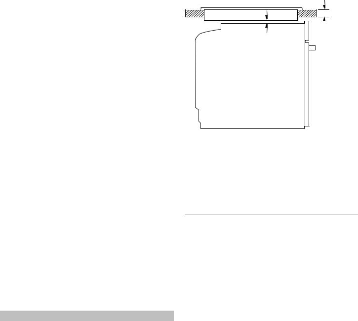
Wird das Gerät unter einem Kochfeld eingebaut, müssen die folgenden Mindestmaße eingehalten werden (gegebenenfalls inklusive Unterkonstruktion):
 D
D
E

Kochfeldart |
a |
a |
b |
|
aufgesetzt |
flächenbündig |
|
|
|
|
|
Induktionskochfeld |
37 mm |
38 mm |
5 mm |
|
|
|
|
Vollflächen- |
43 mm |
48 mm |
5 mm |
Induktionskochfeld |
|
|
|
|
|
|
|
Gaskochfeld |
32 mm |
42 mm |
5 mm |
|
|
|
|
Elektrokochfeld |
22 mm |
24 mm |
2 mm |
Aufgrund des notwendigen Mindestabstandes b ergibt sich die mindeste Arbeitsplattenstärke a.
Die Montageanleitung des Kochfeldes beachten.
Gerät im Hochschrank - Bild 2+4
Der Einbau des Gerätes ist auch im Hochschrank möglich.
Zur Belüftung des Backofens müssen die Zwischnböden einen Spalt von ca. 20 mm zur Anstellwand aufweisen.
Gerät nur so hoch einbauen, dass Backbleche problemlos entnommen werden können.
Eckeinbau - Bild 3
Damit die Gerätetür geöffnet werden kann, beim Eckeinbau Maße D berücksichtigen. Das Maß E ist abhängig von der Dicke der Möbelfront unter dem Griff.
Gerät anschließen
Das Gerät entspricht der Schutzklasse 1 und darf nur mit Schutzleiter-Anschluss betrieben werden.
Bei allen Montagearbeiten muss das Gerät spannungslos sein.
Das Gerät darf nur mit der mitgelieferten Anschlussleitung angeschlossen werden. Stecken Sie die Anschlussleitung an der Geräterückseite an (Click!).
Eine längere Anschlussleitung ist beim Kundendienst erhältlich.
Die Anschlussleitung darf nur durch eine Originalleitung, beziehbar über den Kundendienst, ersetzt werden.
Der Berührungsschutz muss durch den Einbau gewährleistet sein.
Anschlussleitung mit Schutzkontakt-Stecker
Das Gerät darf nur an eine vorschriftsmäßig installierte Schutz- kontakt-Steckdose angeschlossen werden.
Wenn der Stecker nach dem Einbau nicht mehr erreichbar ist muss installationsseitig eine allpolige Trennvorrichtung mit einem Kontaktabstand von mind. 3 mm vorhanden sein.
Anschlussleitung ohne Schutzkontakt-Stecker
Nur ein konzessionierter Fachmann darf das Gerät anschließen. Für ihn gelten die Bestimmungen des regionalen Elektrizitätsversorgers.
In der Installation muss ein allpoliger Trennschalter mit mindestens 3 mm Kontaktöffnung vorhanden sein. Phaseund Neutral- (“Null-“) Leiter in der Anschlussdose identifizieren. Bei Falschanschluss kann das Gerät beschädigt werden.
Nur nach Anschlussbild anschließen. Spannung siehe Typenschild. Die Adern der Netzanschlussleitung entsprechend der Farbcodierung anschließen: grün-gelb = Schutzleiter <, blau = (Null) Neutral-Leiter, braun = Phase (Außenleiter).
Nur GB und Australien
Mindestens mit einem 16 A Stecker anschließen oder mit 16 A absichern.
Nur Schweden, Finnland und Norwegen
Das Gerät kann auch mit dem beigelegten Stecker mit dem Schutzkontakt-System angeschlossen werden. Dieser muss nach dem Einbau zugänglich sein. Ist dies nicht der Fall, muss installationsseitig wieder ein allpoliger Trennschalter mit mindestens 3 mm Kontaktöffnung eingesetzt werden.
Gerät befestigen - Bild 5
■Gerät ganz einschieben und mittig ausrichten.
■Gerät festschrauben.
■Der Spalt zwischen Arbeitsplatte und Gerät darf nicht durch zusätzliche Leisten verschlossen werden.
Ausbau
Gerät spannungslos machen. Befestigungsschrauben lösen. Gerät leicht anheben und ganz herausziehen.
en
Ú
Preparing the units - Fig. 1
■The safe operation of this appliance can only be guaranteed if it has been installed to a professional standard in accordance with these installation instructions. The installer is liable for damage incurred as a result of incorrect installation.
■Fitted units must be heat-resistant up to 90 °C, and neighbouring unit fronts up to 70 °C.
■Cut-out work on the units and worktop should be performed before fitting the appliances. Remove any shavings or the function of the electrical components may be impaired.
■Caution during installation. Parts that are accessible during installation may have sharp edges. Wear protective gloves to prevent cuts
■The power socket for the appliance must either be located in the hatched area B or else away from the installation space.
■A gap of 5 mm is required between the appliance and surrounding unit fronts.
■Secure freestanding units to the wall using a standard bracket
C.
Appliance under worktop – Fig. 1
To ventilate the appliance, the intermediate floor must have a ventilation cut-out.
Secure the worktop to the fitted units.
If the appliance is installed under a hob, the following minimum dimensions must be adhered to (including substructure, if applicable):
 D
D
E
Hob type |
a |
a |
b |
|
Fixed |
Flush with sur- |
|
|
|
rounding surfaces |
|
Induction hob |
37 mm |
38 mm |
5 mm |
|
|
|
|
Full-surface induction hob |
43 mm |
48 mm |
5 mm |
|
|
|
|
Gas hob |
32 mm |
42 mm |
5 mm |
|
|
|
|
Electric hob |
22 mm |
24 mm |
2 mm |
The minimum worktop thickness a results from the minimum required dimension b.
Observe the installation instructions for the hob.
Appliance in a tall unit Figs 2+4
The appliance may also be installed in a tall unit.
There must be a gap between the intermediate floors and the mounting wall of approx. 20 mm in order to provide ventilation to the oven.
Only fit the appliance at a height where removing baking trays does not present a problem.
Corner installation Fig. 3
To ensure that the appliance door can be opened in the case of corner installation, take account of dimension D. Dimension E is dependent on the thickness of the unit front under the handle.
Connecting the appliance to the power supply
The appliance corresponds to protection class I and may only be operated with a protective earth connection.
The appliance must be disconnected from the power supply for all installation work.
The appliance must only be connected with the power cable provided. Connect the power cable to the back of the appliance (listen for the click).
A longer power cable can be obtained from the after-sales service.
The power cable may only be replaced by a cable from the original manufacturer, obtainable via the after-sales service.
Contact protection must be ensured by the installation.
Power cable with a plug with earthing contact
The appliance must only be connected to a properly installed protective contact socket.
If the plug is no longer accessible following installation, an allpole isolating switch must be present on the installation side with a contact gap of at least 3 mm.
Power cable without a plug with earthing contact
Only allow a licenced professional to connect the appliance. He is subject to the regulations of the local electricity provider.
An all-pole isolating switch with at least a 3 mm contact gap must be fitted in the installation. Identify the phase and neutral (zero) conductor in the connection socket. Incorrect connection may cause damage to the appliance.
only connect as per the connection diagram. See the rating plate for the voltage. Connect the wires of the mains power cable according to the colour coding: green/yellow = PE conductor <, blue = neutral conductor, brown = phase (external conductor).
UK and Australia only
Connect using at least a 16 A plug or protect with a 16 A fuse.
Only in Sweden, Finland and Norway
The appliance can also be connected using the plug provided which has an earthing contact system. This must still be accessible after installation. If this is not the case, an all-pole isolating switch must be used on the installation side with a contact gap of at least 3 mm.
Securing the appliance Fig. 5
■Fully insert the appliance and centre it.
■Screw the appliance into place.
■The gap between the worktop and the appliance must not be closed by additional battens.
Removal
Disconnect the appliance from the power supply. Undo the securing screws. Raise the appliance slightly and pull it out completely.
fr
Þ
Préparation du meuble - fig. 1
■Uniquement une installation effectuée selon cette notice de montage garantit une utilisation en toute sécurité. En cas de dommages résultant d'une installation incorrecte, l'installateur est responsable.
■Les meubles d'encastrement doivent résister à des températures jusqu'à 90 °C , les façades des meubles attenants à des températures jusqu'à 70 °C.
■Effectuer tous les travaux de découpe sur le meuble et sur le plan de travail avant d'encastrer les appareils. Enlever les copeaux, le fonctionnement des composants électriques peut être compromis.
■Attention lors de l'encastrement! Des éléments accessibles pendant le montage peuvent posséder des arêtes vives. Porter des gants de protection pour éviter des coupures
■La prise de raccordement de l'appareil doit se situer dans la zone de la surface B ou à l'extérieur de la zone d'encastrement.
■Une fente d'aération de 5mm est nécessaire entre l'appareil et les façades des meubles attenants.
■Les meubles non fixés doivent être vissés au mur avec une équerre usuelle du commerce C.
L'appareil sous le plan de travail - fig. 1
Pour l'aération de l'appareil, le faux-plancher doit présenter une découpe de ventilation.
Fixer le plan de travail sur le meuble d'encastrement.
Si l'appareil est encastré sous une table de cuisson, les cotes minimales suivantes doivent être respectées (le cas échéant, construction support incluse) :
 D
D
E
Type de table de cuisson a |
a |
b |
|
|
posé |
affleurant |
|
|
|
|
|
Table de cuisson à induc- |
37 mm |
38 mm |
5 mm |
tion |
|
|
|
Table de cuisson à induc- |
43 mm |
48 mm |
5 mm |
tion |
|
|
|
pleine surface |
|
|
|
|
|
|
|
Table de cuisson gaz |
32 mm |
42 mm |
5 mm |
|
|
|
|
Table de cuisson élec- |
22 mm |
24 mm |
2 mm |
trique |
|
|
|
En raison de la distance minimale nécessaire b, l'épaisseur minimale du plan de travail qui en découle est a.
Respecter la notice de montage de la table de cuisson.
Appareil dans une armoire fig. 2+4
L'appareil peut également être encastré dans une armoire.
Pour l'aération du four, les faux-planchers doivent présenter une fente d'env. 20 mm vers le mur d'adossement.
Encastrer l'appareil à une telle hauteur que les plaques à pâtisserie pourront être retirées sans problème.
Encastrement angulaire fig. 3
Afin de pouvoir ouvrir la porte de l'appareil, respecter les cotes D en cas d'encastrement angulaire. La cote E est fonction de l'épaisseur de la façade du meuble sous la poignée.
Raccordement de l'appareil
L'appareil répond à la classe de protection 1 et doit uniquement être utilisé avec une prise de terre.
L'appareil doit être mis hors tension pour tous les travaux de montage.
L'appareil doit uniquement être raccordé avec le câble de raccordement fourni. Connectez le câble de raccordement sur le panneau arrière de l'appareil (click !).
Un câble de raccordement plus long est en vente auprès du service après-vente.
Le câble de raccordement doit uniquement être remplacé par un câble d'origine, qui peut être commandé au service aprèsvente.
L'encastrement doit garantir la protection contre les contacts accidentels.
Câble de raccordement avec fiche avec terre
L'appareil doit être raccordé impérativement à une prise avec terre installée de manière réglementaire.
Si, après l'encastrement de l'appareil, la prise n'est plus accessible, il faudra installer, côté secteur, un sectionneur omnipolaire avec un interstice d'ouverture de contact d'au moins 3 mm.
Câble de raccordement sans fiche avec terre
Seul un spécialiste agréé est habilité à raccorder l'appareil. Il doit appliquer les réglementations du fournisseur d'électricité régional.
Un sectionneur omnipolaire avec un interstice d'ouverture de contact d'au moins 3 mm doit être présent dans l'installation. Identifier le conducteur de phase et le conducteur neutre dans la prise de raccordement. En cas de branchement erroné, l'appareil peut subir des dommages.
Loading...