


2 609 140 081 - Buch Seite 1 Dienstag, 20. Januar 2004 8:52 08
GWS 6-100 (E) GWS 6-115 (E) GWS 8-100 C (CE) GWS 8-115 C (CE) GWS 8-125 C (CE) PROFESSIONAL
* Des idées en action.
Bedienungsanleitung Operating instructions Instructions d’emploi Instrucciones de servicio Manual de instruções Istruzioni d’uso Gebruiksaanwijzing Betjeningsvejledning Bruksanvisning Brukerveiledningen Käyttöohje
δηγία ειρισµ ύ
Kullan∂m k∂lavuzu

2 609 140 081 - Buch Seite 2 Dienstag, 20. Januar 2004 8:52 08
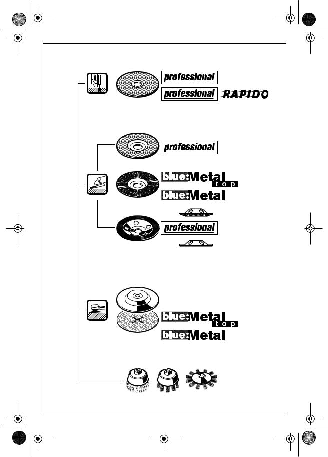
(M 10) 2 605 703 030 (M 14) 1 605 703 099
(M 14) 1 600 210 039
(M 14) 1 603 340 031
 (M 10) 2 603 340 018 (M 14) 1 603 340 040
(M 10) 1 607 950 040 (M 14) 2 607 950 043
1 602 025 024
 1 601 329 013
Ø 100 mm 2 605 510 155


 Ø 115 mm 2 605 510 156 Ø 125 mm 2 605 510 172
Ø 100 –125 mm 1 610 510 197


 2 x 2 605 730 036
2 605 438 343
2 • 2 609 140 081 • 04.01
2 609 140 081 - Buch Seite 3 Dienstag, 20. Januar 2004 8:52 08
3 • 2 609 140 081 • 04.01

2 609 140 081 - U4+5 Seite 4 Dienstag, 20. Januar 2004 8:05 08
1
2
3
|
4 |
|
|
|
5 |
|
|
6 |
|
|
|
7 |
|
|
|
|
12 |
|
12 |
8 |
|
|
|
|
13 |
|
16 |
9 |
|
|
|
|
14 |
|
GWS 6-100 E |
|
|
|
GWS 6-115 E |
|
|
|
GWS 8-100 CE |
10 |
|
15 |
GWS 8-115 CE |
|
GWS 8-125 CE |
||
11 |
|
|
|
|
|
PROFESSIONAL |
|
4 + 5 • 2 609 140 081 • 04.01 |
|
|
|
2 609 140 081 - Buch Seite 1 Dienstag, 20. Januar 2004 8:52 08
Tool Specifications
Angle Grinder GWS … |
|
6-100 |
6-100 E |
6-115 |
6-115 E |
||||||||
PROFESSIONAL |
|
|
|
|
|
|
|
|
|
|
|
|
|
Order number |
|
0 601 375 0.. |
0 601 375 7.. |
0 601 375 0.. |
0 601 375 7.. |
||||||||
Rated input power* |
[W] |
670 |
670 |
670 |
670 |
||||||||
Output power* |
[W] |
400 |
400 |
400 |
400 |
||||||||
No-load speed |
[rpm] |
11 000 |
|
2 800 – |
11 000 |
|
2 800 – |
||||||
|
|
|
|
|
11 000 |
|
|
|
11 000 |
||||
Grinding disc dia., max. |
[mm] |
100 |
100 |
115 |
115 |
||||||||
Grinder spindle thread |
|
M 10 |
M 10 |
M 14 |
M 14 |
||||||||
Constant Electronic Control |
|
– |
– |
– |
– |
||||||||
Speed Preselection |
|
– |
● |
– |
● |
||||||||
Weight without cable, approx. |
[kg] |
1.4 |
1.4 |
1.4 |
1.4 |
||||||||
Protection class |
|
|
|
/ II |
|
|
/ II |
|
|
/ II |
|
|
/ II |
|
|
|
|
|
|
|
|
|
|
|
|
|
|
Angle Grinder GWS … |
|
|
8-100 C |
8-100 CE |
8-115 C/ |
8-115 CE/ |
|||||||
PROFESSIONAL |
|
|
|
|
|
|
|
8-125 C |
8-125 CE |
||||
Order number |
|
|
0 601 377 ... |
0 601 378 ... |
0 601 377 ... |
0 601 378 ... |
|||||||
Rated input power* |
[W] |
|
850 |
850 |
850 |
850 |
|||||||
Output power* |
[W] |
|
490 |
490 |
490 |
490 |
|||||||
No-load speed |
[rpm] |
|
11 000 |
|
2 800 – |
11 000 |
|
2 800 – |
|||||
|
|
|
|
|
11 000 |
|
|
|
11 000 |
||||
Grinding disc dia., max. |
[mm] |
|
100 |
100 |
115/125 |
115/125 |
|||||||
Grinder spindle thread |
|
|
M 10 |
M 10 |
M 14 |
M 14 |
|||||||
Constant Electronic Control |
|
|
● |
● |
● |
● |
|||||||
Speed Preselection |
|
|
– |
● |
– |
● |
|||||||
Weight without cable, approx. |
[kg] |
|
1.5 |
1.5 |
1.5 |
1.5 |
|||||||
Protection class |
|
|
|
/ II |
|
|
/ II |
|
|
/ II |
|
|
/ II |
Please observe the order number of your machine. The trade names of the individual machines may vary.
* The values given are valid for nominal voltages [U] of 230/240 V. For lower voltages and models for specific countries, these values can vary.
Speed Preselection
(GWS 6-100 E, GWS 6-115 E, GWS 8-100 CE, GWS 8-115 CE, GWS 8-125 CE)
Material |
Application |
Tool |
Thumbwheel |
Plastic |
Polishing |
Lamb’s wool hood |
1 |
|
Finish polishing |
Felt polishing disk |
1 |
Metal |
Finish grinding |
Buffing disk |
1 |
|
Removing paint |
Sanding sheet |
2 – 3 |
Wood, Metal |
Brushing, Removing rust |
Cup brush, sanding sheet |
3 |
Metal, Stone |
Grinding |
Grinding disk |
4 – 6 |
Metal |
Roughing |
Grinding disc |
6 |
13 • 2 609 140 081 • TMS • 15.01.04 |
English - 1 |
2 609 140 081 - Buch Seite 2 Dienstag, 20. Januar 2004 8:52 08
Machine Elements |
|
Intended Use |
|
|
|
The numbering of the device elements refers to the illustration of the machine on the graphics page.
While reading the operating instructions, unfold the graphics page for the device and leave it open.
1Thumbwheel for speed preselection (GWS 6-100 E, GWS 6-115 E, GWS 8-100 CE, GWS 8-115 CE, GWS 8-125 CE)
2On/Off switch
3Auxiliary handle
4Spindle lock button
5Grinder spindle
6Protection guard
7Screw
8Mounting flange
(for the M 14 grinding spindle with O-ring)
9Grinding-/cutting disc*
10Clamping nut
11


 quick-clamping nut* (for M 14 grinder spindle)
12Hand guard*
13Rubber sanding plate*
14Sanding sheet*
15Round nut*
16Cup brush*
17Mounting flange M 10
*Not all of the accessories illustrated or described are included as standard delivery.
Noise/Vibration Information
Measured values determined according to EN 50 144.
Typically the A-weighted noise levels of the machine are: Sound pressure level: 89 dB (A); sound power level: 102 dB (A).
Wear hearing protection!
The typically weighted acceleration is 5.0 m/s2.
The machine is intended for cutting, roughing and brushing metal and stone materials without using water. For cutting stone, a cutting guide is required.
For machines with electronic control: With approved sanding tools, the machine can be used for sanding and polishing.
Information on Structures
Slots in structural walls are subject to the Standard DIN 1053, Part 1 or country-specific regulations.
These regulations are to be observed under all circumstances. Before beginning work, consult the responsible structural engineer, architects or the construction supervisor.
For Your Safety
Working safely with this machine is possible only when the operating and safety information are read completely and the instructions contained therein are strictly followed. In addition, the
general safety notes in the enclosed booklet must be observed. Before using for the first time, ask for a practical demonstration.
■Wear protective glasses and hearing protection.
■Wear additional protection equipment for your safety, such as protective gloves, sturdy shoes, hard hat and apron.
■The dust that is produced while working can be detrimental to health, inflammable or explosive. Suitable safety measures are required.
Examples: Some dusts are regarded as carcinogenic. Use suitable dust/chip extraction and wear a dust respirator.
■Dust from light alloys can burn or explode. Always keep the workplace clean, as blends of materials are particularly dangerous.
■If the mains cable is damaged or cut through while working, do not touch the cable but immediately pull the mains plug. Never use the machine with a damaged cable.
14 • 2 609 140 081 • TMS • 15.01.04 |
English - 2 |
2 609 140 081 - Buch Seite 3 Dienstag, 20. Januar 2004 8:52 08
■Connect machines that are used in the open via a residual current device (RCD) with an actuating current of 30 mA maximum. Do not operate the machine in rain or moisture.
■When working with the machine, always hold it firmly with both hands and provide for a secure stance.
■Secure the workpiece. A workpiece clamped with clamping devices or in a vice is held more secure than by hand.
■Always direct the cable to the rear away from the machine.
■Always switch the machine off and wait until it has come to a standstill before placing it down.
■For power outage or when the mains plug is pulled, unlock the On/Off switch immediately and turn it to the off position. This prevents uncontrolled restarting.
■The machine must be used only for dry cutting/ grinding.
■For all work with the machine, the auxiliary handle must be mounted.
■Hold the power tool only by the insulated gripping surfaces, when performing an operation where the cutting tool may run into hidden wiring or its own cord.
Contact with a “live” wire will make exposed metal parts of the tool “live” and shock the operator.
■Use appropriate detectors to determine if utility lines are hidden in the work area or call the local utility company for assistance.
Contact with electric lines can lead to fire and electric shock. Damaging a gas line can lead to explosion. Penetrating a water line causes property damage or may cause an electric shock.
■For work with grinding or cutting discs, the protection guard 6 must be mounted. For work with the rubber sanding plate 13 or with the cup brush 16/disc brush/flap disc, the hand guard 12 (accessory) is to be mounted.
■Use dust extraction when working with stone. The vacuum cleaner must be approved for masonry dust. When cutting stone, use the cutting guide.
■Do not work with materials containing asbestos.
■Use only grinding tools with a permissible speed at least as high as the no-load speed of the machine.
■Check grinding tools before use. The grinding tool must be properly mounted and turn freely. Perform a test run for at least 30 seconds without load. Do not use damaged, out-of-round or vibrating grinding tools.
■Protect the grinding tool from impact, shock and grease.
■Apply the machine to the workpiece only when switched on.
■Keep hands away from rotating grinding tools.
■Pay attention to the direction of rotation. Always hold the machine so that sparks and grinding dust fly away from the body.
■When grinding metal, flying sparks are produced. Take care that no persons are endangered. Due to danger of fire, no combustible materials should be located in the vicinity (spark flight zone).
■Be careful when cutting grooves, e. g. in structural walls: See Information on Structures.
■Blocking the cutting disc leads to jerking reaction forces on the machine. In this case switch off the machine immediately.
■Observe the dimensions of the grinding discs.
The hole diameter must fit mounting flange 8 (M 14), 17 (M 10). Do not use any reducers or adapters.
■Never use cutting discs for rough grinding. Do not exert any lateral pressure on the cutting discs.
■Observe the manufacturer’s instructions for mounting and using grinding tools.
■Caution! The grinding tool runs on after the machine is switched off.
■Do not clamp the machine in a vice.
■Never allow children to use the machine.
■Bosch is only able to ensure perfect operation of the machine if the original accessories intended for it are used.
15 • 2 609 140 081 • TMS • 15.01.04 |
English - 3 |
2 609 140 081 - GB Seite 4 Dienstag, 20. Januar 2004 11:34 11
Mounting the
Protective Devices
■Before any work on the machine itself, pull the mains plug.
Protection Guard
■For work with grinding or cutting discs, the protection guard 6 must be mounted.
Place the protection guard 6 on the spindle collar. Adjust the position of the protection guard 6 to the requirements of the work process. Clamp with the screw 7.
The closed side of the protection guard 6 must always point to the operator.
Auxiliary Handle
■For all work with the machine, the auxiliary handle must be mounted.
Screw the auxiliary handle 3 on the right or left of the machine head depending on the working method.
Hand Guard
For work with the rubber sanding plate 13 or with the cup brush 16/disc brush/flap disc, the hand guard 12 (accessory) is to be mounted. The hand guard 12 is fastened with the auxiliary handle 3.
Mounting the Grinding Tools
■Before any work on the machine itself, pull the mains plug.
Use only grinding tools with a permissible speed at least as high as the no-load speed of the machine.
Grinding and cutting discs become very hot while working; do not touch until they have cooled.
■Clean the grinder spindle and all parts to be mounted. For clamping and loosening the grinding tools, lock the grinder spindle 5 with the spindle lock button 4.
Actuate the spindle lock button 4 only when the grinder spindle is at a standstill!
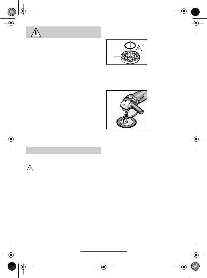
Grinding-/Cutting Disc
■ Observe the dimensions of the grinding discs. The hole diameter must fit mounting flange 8 (M 14), 17 (M 10). Do not use any reducers or adapters.
For mounting, see the illustration page.
Screw on the clamping nut 10 and tighten with the two-pin spanner (see Section “Quick Clamping Nut”).
|
Mounting flange for |
||
|
grinding |
spindle |
|
|
M 14 |
|
|
8 |
An |
O-ring (plastic |
|
part) |
is |
inserted in |
|
|
the |
|
mounting |
|
flange 8 |
around the |
|
|
spigot. |
|
|
If the O-ring is missing or is damaged, it must in all cases be replaced (Order No. 1 600 210 039) before the mounting flange 8 is mounted.
17 |
Mounting flange for grinding spindle M 10
The supporting flange 17 can be used on both sides.
Do not use any reducers or adapters.
After mounting the grinding tool and before switching on, check that the grinding tool is correctly mounted and that it can turn freely.
Flap Disc
(for M 14 grinder spindle)
Depending on the application, remove the protection guard 6 and mount the hand guard 12. Place the special mounting flange 8 (accessory, Order No. 2 605 703 028) and the flap disc on the grinder spindle 5. Screw on the clamping nut 10 and tighten with the two-pin spanner.
Rubber Sanding Plate 13
Depending on the application, remove the protection guard 6 and mount the hand guard 12.
For mounting, see the illustration page.
Screw on the round nut 15 and tighten with the two-pin spanner.
16 • 2 609 140 081 • TMS • 15.01.04 |
English - 4 |
2 609 140 081 - Buch Seite 5 Dienstag, 20. Januar 2004 8:52 08
Cup Brush 16/Disc Brush
(for M 14 grinder spindle)
Depending on the application, remove the protection guard 6 and mount the hand guard 12.
The grinding tool must be able to be screwed onto the grinding spindle 5 until it rests firmly against the grinder spindle flange at the end of the grinder spindle threads. Tighten with an open-end spanner.
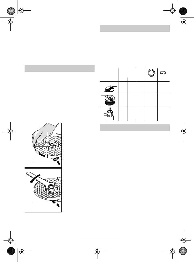
Quick Clamping Nut 


(for M 14 grinder spindle)
Instead of the clamping nut 10, the quick-clamp- ing nut 11 (accessory) can be used. Grinding tools can then be mounted without using tools.
The quick-clamping nut 11 may be used only for grinding and cutting discs.
Use only a flawless, undamaged quick-clamp- ing nut 11.
When screwing on, take care that the side with printing does not point to the grinding disc. The arrow must point to the index mark 18.
18 |
11 |
4 |
4 |
Lock the grinder spindle with the spindle lock button 4. Tighten the quickclamping nut by forcefully turning the grinding disc in the clockwise direction.
A properly tightened undamaged, quickclamping nut can be loosened by hand turning the knurled ring in anticlockwise direction.
Never loosen a tight quick-clamping nut with pliers but use a two-pin spanner. Insert the two-pin spanner as shown in the illustration.
Approved Grinding Tools
All grinding tools mentioned in this operating manual instruction can be used.
The permissible speed [rpm] or the circumferential speed [m/s] of the grinding tools used must at least match the values given in the table.
Therefore, always observe the permissible rotational/circumferential speed on the label of the grinding tool.
|
|
max. |
|
|
|
||
|
|
[mm] |
[mm] |
|
|
||
|
|
D |
b |
d |
[rpm] |
[m/s] |
|
d |
|
100 |
6 |
16.0 |
11 000 |
80 |
|
|
D |
115 |
6 |
22.2 |
11 000 |
80 |
|
b |
125 |
6 |
22.2 |
11 000 |
80 |
||
|
|||||||
D |
|
100 |
– |
– |
11 000 |
80 |
|
|
115 |
– |
– |
11 000 |
80 |
||
|
|
||||||
|
|
125 |
– |
– |
11 000 |
80 |
|
d |
|
70 |
30 |
M 10 |
11 000 |
45 |
|
b |
|
||||||
|
75 |
30 |
M 14 |
11 000 |
45 |
||
D |
|
|
|
|
|
|
|
Starting Operation
Observe correct mains voltage: The voltage of the power source must agree with the voltage specified on the nameplate of the machine. Equipment marked with 230 V can also be connected to 220 V.
To start the machine, press the On/Off switch 2 forward.
To lock-on, press the On/Off switch 2 down at the front until it engages.
To switch off the machine, release the On/Off switch 2 or press the rear tip of it down.
Test run!
Check the grinding tool before use. The grinding tool must be properly mounted and rotate freely. Perform a test run of at least 30 seconds without load. Do not use damaged, out-of-round or vibrating grinding tools.
17 • 2 609 140 081 • TMS • 15.01.04 |
English - 5 |
 Loading...