


Applications manual
For tankless and point of use water heaters

2 | Applications manual
Table of Contents
1 Introduction |
3 |
|
2 Bosch Water Heating Models |
3 |
|
2.1 |
Sizing tankless water heaters |
4 |
2.2 Bosch GWH 715 ES |
6 |
|
2.3 Bosch GWH C 800 ES |
7 |
|
2.4 |
Outdoor Installation for GWH 715 ES and GWH C 800 ES |
8 |
2.5 Bosch GWH 345 ESR |
9 |
|
2.6 Bosch GWH 450 ESR |
10 |
|
2.7 Bosch GWH 425 EF |
11 |
|
2.8 Bosch GWH 425 HN |
12 |
|
2.9 Bosch GWH 425 PN |
13 |
|
2.10 Bosch GWH 260 PN |
14 |
|
2.11 Powerstream Pro RP17PT, RP27PT |
15 |
|
2.12 Powerstream Pro RP1P, RP2P, RP3P, RP7P, RP9P, RP12PT |
16 |
|
2.13 Ariston Pro GL2.5Ti, GL4Ti, GL8Ti |
17 |
|
3 Domestic Water Heating Applications |
18 |
|
3.1 |
Point-of-use applications |
18 |
3.2 |
Whole house applications |
22 |
4 High Volume Potable Water Heating |
26 |
|
4.1 |
Parallel unit applications |
26 |
4.2 |
Cascade unit applications |
28 |
4.3 |
External storage tank loading applications |
29 |
5 Open Loop Space Heating |
32 |
|
5.1 |
External storage tank |
32 |
5.2 |
Indirect tank applications |
42 |
6 Maintenance Drawings |
44 |
|
6.1 |
Descaling procedure |
44 |
6.1 |
Descaling procedure diagram |
45 |
Application manual | 11.2007 |
Bosch Water Heating |

Applications manual |
| 3 |
|
|
1 Introduction
The Bosch Applications Manual is intended to present some of the most common applications of the Bosch line of tankless and point of use water heaters. Application drawings are shown with both piping and corresponding electrical schematics where applicable. Auxiliary equipment depicted does not necessarily represent any one manufacturer or specific model number. There are a wide variety of techniques, practices and piping strategies possible when installing water heating appliances. It is the responsibility of the installing contractor to determine the most suitable arrangement for the application.
Although this manual covers many common applications for our products, system possibilities are virtually endless. Should you encounter an application that is not covered in this manual or have any questions regarding any of its content, we encourage you to contact your local sales representative or us directly at Bosch Water Heating.
This is not a substitute for any of the product’s installation manuals. All specifications subject to change.
Installation must conform with local codes or, in the absence of local codes, the National Fuel Gas Code ANSI Z 223.1/NFPA 54. In Canada: Installation must conform with CGA B149.(1,2) INSTALLATION CODES and/or local installation codes.
2 Bosch Water Heating Models
This section describes the water heaters available from Bosch Water Heating. The information given in each section provides a general overview to the specifications of that particular model. More detailed information is contained in the installation manuals. Download these manuals at www.BoschPro.com.
Bosch Water Heating |
Applications manual | 11.2007 |

4 | |
Applications manual |
|
|
2.1 Sizing tankless water heaters
Definitions
Major applications (2 GPM or more): Washing machine, bath tub, shower nozzle
Minor applications(1.5 GPM or less): Low flow shower head, bathroom sink, kitchen sink
Rule of thumb sizing
The tables below provide a general rule of thumb when sizing for most residential applications. For commercial applications or for a more detailed sizing method, use the instructions below in conjunction with the charts on the next page.
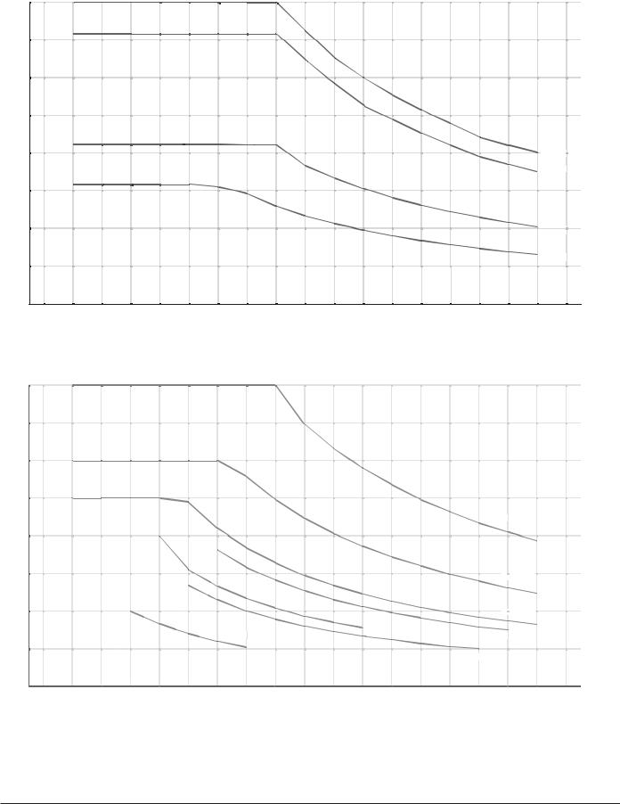
Sizing by Chart
Measure the flow rates at each fixture that will be used simultaneously and add them together. If only one application will be used at a time measure each fixture and use the maximum flow rate observed.
Rule of Thumb Sizing
Model Number |
Number of Major |
Number of Minor |
|
Applications |
Applications |
|
|
|
GWH 715 ES |
2 |
0 |
|
|
|
GWH C 800 ES |
2 |
1 |
|
|
|
GWH 425 HN/PN/EF |
1 |
1 |
|
|
|
GWH 425 HN/PN/EF |
0 |
2 |
|
|
|
GWH 260 PN |
1 |
0 |
|
|
|
RP17PT |
1 |
0 |
|
|
|
RP27PT |
1 |
1 |
|
|
|
Using a known volume container, record several fill times. Perform the calculation below to determine the flow rate (a one gallon fill time of 30 seconds is 2.0 gallons per minute (GPM):
Flow rate (GPM) = |
Volume (gallons) |
x 60 |
sec |
|
Fill time (sec) |
min |
|||
|
|
Using a thermometer, measure the incoming water temperature. Subtract this temperature from the desired hot water temperature to get the degree rise. So, if the desired hot water temperature is 120F and incoming temperature is 55F, the desired degree rise is 65F.
This example requires a flow rate of 2.0 GPM at a 65˚F rise. The data point is shown on each graph. Since the demand is above the GWH 260 PN capacity, this application would require a GWH 425 HN/PN/EF gas tankless water heater. The electrical model used for this application would be the RP27PT electric tankless water heater.
Application manual | 11.2007 |
Bosch Water Heating |
Applications manual |
| 5 |
|
|
GPM |
|
|
|
|
|
|
|
|
8 |
|
|
|
|
|
|
|
|
7 |
|
|
|
|
|
|
|
|
6 |
|
|
|
|
|
|
|
|
5 |
|
|
|
|
|
|
|
|
4 |
|
|
|
|
|
|
|
GWH C 800 ES |
|
|
|
|
|
|
|
|
GWH 715 ES |
3 |
|
|
|
|
|
|
|
|
2 |
|
|
|
|
|
|
|
GWH 425 PN/HN |
|
|
|
|
|
|
|
|
GWH 260 PN/HN |
1 |
|
|
|
|
|
|
|
|
0 |
|
|
|
|
|
|
|
|
10 |
20 |
30 |
40 |
50 |
60 |
70 |
80 |
90 |
Degree rise (°F)
Gas Appliance Sizing Chart
GPM
4.0
3.5
3.0
2.5
RP27PT
2.0
1.5 |
|
|
|
|
|
|
|
|
|
|
|
|
|
|
|
|
|
|
|
|
|
|
|
|
|
RP17PT |
|||
1.0 |
|
|
|
|
|
|
|
|
|
|
||||
|
|
RP3P |
|
RP7P |
|
|
|
|
|
|
RP12PT |
|
||
|
|
|
|
|
|
|
|
|
||||||
|
|
|
|
|
|
|
|
R |
P |
1P |
||||
|
|
|
|
|
|
|
|
|
||||||
0.5 |
|
|
|
|
|
|
RP |
|
9P |
|
|
|
|
|
|
|
|
|
|
|
|
|
|
|
|
|
|
||
0.0 |
|
|
|
|
|
|
|
|
|
|
|
|
|
|
10 |
20 |
30 |
40 |
50 |
60 |
70 |
80 |
90 |
||||||
Degree rise
Electric Appliance Sizing Chart
Note: Maximum flow rates dependant on site conditions
Bosch Water Heating |
Applications manual | 11.2007 |
6 |
2.2 Bosch GWH 715 ES
Features:
Electronic ignition and built in power vent 82% thermal efficiency
Vents vertically or horizontally with 3" or 4" stainless steel (AL294C)
Direct vent room-sealed combustion
Computerized temperature control — ensures temperature stability Model GWH 715 ES N for natural gas (NG) supply
Model GWH 715 ES L for liquid propane (LP) supply 15-year warranty
Qualifies for $300 tax credit
GWH 715 ES Technical Specifications
Gas input |
Natural Gas: 19,900 - 199,000 BTU |
|
|
|
|
|
LP Gas: 19,900 - 199,000 BTU |
|
|
|
|
Minimum flow to activate |
0.65 gallons per minute (gpm) |
|
|
|
|
Flow rates |
45˚F rise @ 7.2 gpm |
|
|
55˚F rise @ 5.9 gpm |
|
|
65˚F rise @ 5.0 gpm |
|
|
77˚F rise @ 4.2 gpm |
|
|
90˚F rise @ 3.6 gpm |
|
|
|
|
Thermal Efficiency |
NG: 82% LP: 82% |
|
Dimensions |
30½" h x 17⅞" w x 11¼" d |
|
Weight |
67 lbs. |
|
Modulating gas valve |
yes |
|
|
|
|
Ignition |
Electronic |
|
|
|
|
Accessories |
Outdoor kit (PTOK) |
|
|
Wireless Remote (TSTAT2) |
|
|
Tankless Link Cascading Kit (TLINK) |
|
|
Freeze Prevention Kit (8700400022) |
|
|
Water Filter Kit (8703305356) |
|
|
|
|
|
||
GWH 715 ES Installation Specifications |
|
|
Gas connection |
¾" Male NPT |
|
|
|
|
Water connections |
¾" Male NPT |
|
NG gas pressure |
Minimum: 4" W.C. |
|
|
Maximum: 14" W.C. |
|
|
|
|
LP gas pressure |
Minimum: 9" W.C. |
|
|
Maximum: 14" W.C. |
|
|
|
|
Water pressure |
Minimum: 30 PSI |
|
(Static) |
Minimum well pressure: 40 PSI |
|
|
Maximum: 150 PSI |
|
Electrical supply |
120VAC - plugs in |
|
Venting |
3" or 4" stainless steel (AL29-4C) |
|
|
direct vent |
|
|
room-sealed combustion |
|
|
|
|
Applications manual
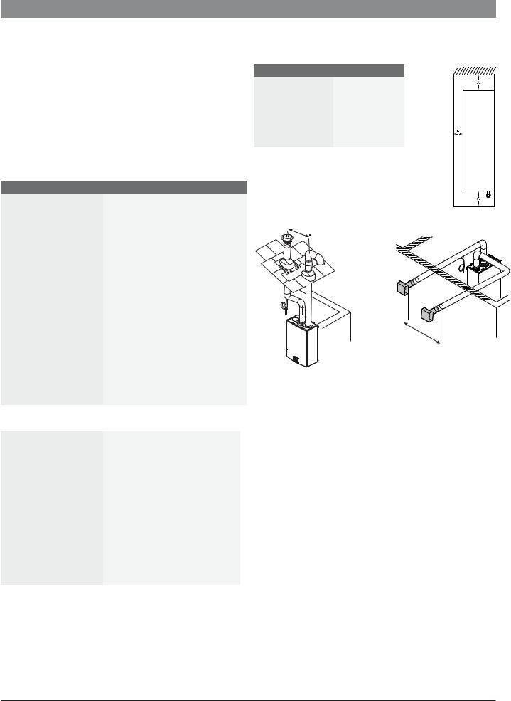
GWH 715 ES Installation Clearances
Top (A) |
12" |
|
|
Front (B) |
1" |
|
|
Back |
0" |
|
|
Sides |
1" |
|
|
Floor (C) |
12" |
|
|
3ft minimum distance
3ft minimum distance
Fig. 1 Venting configurations
Installation guidelines:
Venting:
Must be 3" or 4" AL29-4C sealed stainless steel vent pipe. Slope horizontal runs up to termination ¼" per foot. The last horizontal section of exhaust vent pipe between last elbow and termination must slope down to the termination ¼" per foot. Do not combination vent with any other appliance.
Install condensate drain where applicable. See manual for vent terminator clearances.
Gas piping:
Heater will not function properly without adequate supply gas pressure.
Any appliance connector should be ¾" minimum diameter
Plumbing:
Install the included pressure relief valve and pipe to suitable drain.
Minimum piping diameter is ¾".
Do not solder directly to the bottom of the unit. Use unions to facilitate easy future maintenance. Use full port ball valves for isolation valves.
Partially fill condensate drain tube loop (where applicable) with water prior to start up.
Application manual | 11.2007 |
Bosch Water Heating |

Applications manual |
| 7 |
|
|
2.3 Bosch GWH C 800 ES
Features:
Electronic ignition and built in power vent Condensing technology with 92% thermal efficiency
Vents vertically or horizontally with 3" or 4" PVC, CPVC or ABS (Schedule 40) vent pipe.
Direct vent room-sealed combustion with concentric venting option
Computerized temperature control — ensures temperature stability Model GWH C 800 ES N for natural gas (NG) supply
Model GWH C 800 ES L for liquid propane (LP) supply 15-year warranty
Qualifies for $300 tax credit
GWH C 800 ES Technical Specifications
Gas input |
Natural Gas: 19,900 - 199,000 BTU |
|
|
|
|
|
LP Gas: 19,900 - 199,000 BTU |
|
|
|
|
Minimum flow to activate |
0.65 gallons per minute (gpm) |
|
Flow rates |
45˚F rise @ 8.0 gpm |
|
|
55˚F rise @ 6.4 gpm |
|
|
65˚F rise @ 5.5 gpm |
|
|
77˚F rise @ 4.6 gpm |
|
|
90˚F rise @ 3.9 gpm |
|
|
|
|
Thermal Efficiency |
NG: 92% LP: 92% |
|
|
|
|
Dimensions |
30½" h x 17⅞" w x 11¼" d |
|
|
|
|
Weight |
74 lbs. |
|
|
|
|
Modulating gas valve |
yes |
|
|
|
|
Ignition |
Electronic |
|
Accessories |
Outdoor kit (PTOK) |
|
|
Wireless Remote (TSTAT2) |
|
|
Tankless Link Cascading Kit (TLINK) |
|
|
Freeze Prevention Kit (8700400022) |
|
|
Water Filter Kit (8703305356) |
|
|
Concentic Termination Kit |
|
|
(BWH60L46) |
|
|
||
GWH C 800 ES Installation Specifications |
|
|
Gas connection |
¾" Male NPT |
|
|
|
|
Water connections |
¾" Male NPT |
|
|
|
|
NG gas pressure |
Minimum: 4" W.C. |
|
|
Maximum: 14" W.C. |
|
|
|
|
LP gas pressure |
Minimum: 9" W.C. |
|
|
Maximum: 14" W.C. |
|
|
|
|
Water pressure |
Minimum: 30 PSI |
|
(Static) |
Minimum well pressure: 40 PSI |
|
|
Maximum: 150 PSI |
|
Electrical supply |
120VAC - plugs in |
|
Venting |
3" or 4" PVC, CPVC, or ABS |
|
|
(Schedule 40) direct vent sealed |
|
|
combustion |
|
|
|
|
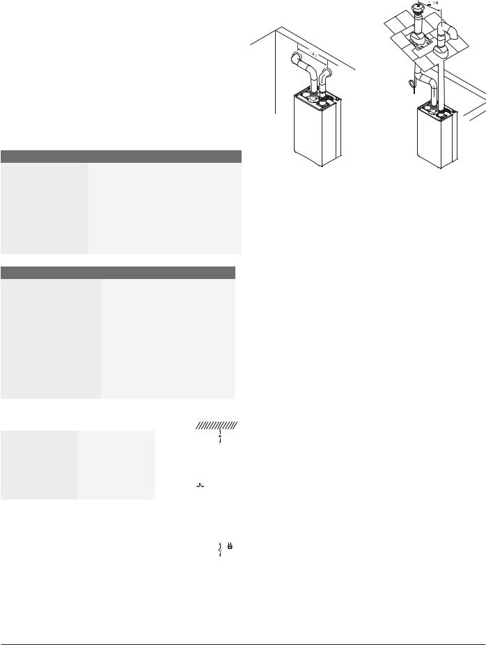
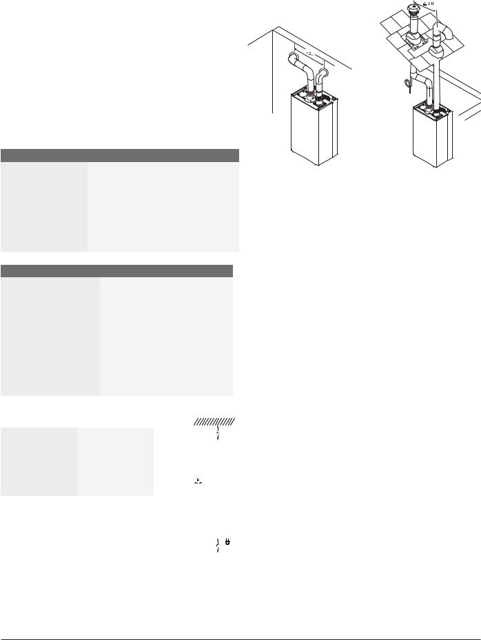
GWH C 800 ES Installation Clearances
Top (A) |
12" |
|
|
Front (B) |
1" |
|
|
Back |
0" |
|
|
Sides |
1" |
|
|
Floor (C) |
12" |
|
|
MAINTAIN 12 IN. |
|
|
(18 IN. FOR CANADA) |
VENT |
|
MINIMUM CLEARANCE |
||
ABOVE |
|
|
HIGHEST ANTICIPATED |
|
|
SNOW LEVEL. |
COMBUSTION |
|
MAXIMUM OF 24 IN. |
AIR |
|
ABOVE ROOF. |
||
|
ROOF BOOT/ |
|
|
FLASHING (FIELD |
|
|
SUPPLIED |
|
|
|
|
MINIMUM |
|
|
1” |
INTAKE |
|
|
EXHAUST |
INTAKE |
VENT |
|
||
|
|
EXHAUST |
|
|
COMBUSTION |
|
|
AIR |
DRAIN TEE |
|
DRAIN TEE |
|
|
Fig. 1 Venting configurations
Installation guidelines:
Venting:
Must be 3" or 4" PVC, CPVC or ABS (Schedule 40) vent pipe. Attach drain for internal condensate siphon and dispose of according to local codes.
Do not combination vent with any other appliance. Install an external condensate drain where applicable. See manual for vent terminator clearances.
Gas piping:
Heater will not function properly without adequate supply gas pressure.
Any appliance connector should be ¾" minimum diameter
Plumbing:
Install the included pressure relief valve and pipe to suitable drain.
Minimum piping diameter is ¾".
Do not solder directly to the bottom of the unit. Use unions to facilitate easy future maintenance. Use full port ball valves for isolation valves.
Partially fill condensate drain tube loop (where applicable)
Bosch Water Heating |
Applications manual | 11.2007 |

8 | Applications manual
2.4 Outdoor Installation for GWH 715 ES, |
Installation on wood siding |
|
|
|
|
|
|
|
|
|
|
|||
and GWH C 800 ES |
|
|
|
|
|
|
|
|
|
|
|
|
|
|
Outdoor Kit (PTOK) installation: |
|
|
|
|
|
|
|
|
|
|
|
|
|
|
The installation of this outdoor kit (PTOK) is required when |
|
|
|
|
|
|
|
|
|
|
|
|
|
|
installing either of the above appliances outdoors |
|
|
|
|
|
|
|
|
|
|
|
|
|
|
Outdoor cap easily retrofits to these indoor models |
|
|
|
|
|
|
|
|
|
|
|
|
|
|
Outdoor kit comes with Freeze Prevention which must be installed |
|
|
|
|
|
|
|
|
|
|
|
|
|
|
Exterior water piping should be protected if freezing conditions |
|
|
|
|
|
|
|
|
|
|
|
|
|
|
could exist |
|
|
|
|
|
|
|
|
|
|
|
|
|
|
Minimum clearances: |
|
|
|
|
|
|
|
|
|
|
|
|
|
|
|
|
|
|
|
|
|
|
|
|
|
|
|
|
|
|
|
|
|
|
|
|
|
|
|
|
|
|
|
|
|
|
|
|
|
|
|
|
|
|
|
|
|
|
|
|
|
|
|
|
|
|
|
|
|
|
|
|
|
|
|
|
|
|
|
|
|
|
|
|
|
|
|
|
|
|
|
|
|
|
|
|
|
|
|
|
|
|
|
|
|
|
|
|
|
|
|
|
|
|
|
|
|
|
|
|
|
|
|
|
|
|
|
|
|
|
|
|
|
|
|
|
|
|
|
|
|
|
|
|
|
|
|
|
|
|
|
|
|
|
|
|
|
|
|
|
|
|
|
|
|
|
|
|
|
|
|
|
|
|
|
|
|
|
|
|
|
|
|
|
|
|
|
|
|
|
|
|
|
|
|
|
|
|
|
|
|
|
|
|
|
|
|
|
|
|
|
|
|
|
|
|
|
|
|
|
|
|
|
|
|
|
|
|
|
|
|
|
|
|
|
|
|
|
|
|
|
|
|
|
|
|
|
|
|
|
|
|
|
|
|
|
|
|
|
|
|
|
|
|
|
|
|
|
|
|
|
|
|
|
|
|
|
|
|
|
|
|
|
|
Installation on vinyl siding:
Ref. |
Description |
Min. |
|
distances |
|||
|
|
||
A |
Directly below or adjacent to |
|
|
|
an opening; operable |
≥ 4 ft |
|
B |
|||
windows, doors and any fresh |
|||
|
|
||
C |
air openings |
|
|
|
|
|
|
D |
From any adjacent wall |
≥ 4 ft |
|
|
|
|
|
E |
Below a gutter, sanitary |
≥ 3 ft |
|
pipework, eaves or overhang |
|||
|
|
||
|
|
|
|
F |
Above ground |
≥ 1 ft |
|
|
|
|
|
G |
From a gas meter or gas |
≥ 5 ft |
|
regulator |
|||
|
|
||
Outdoor Installation Clearances |
|
||
Source: NFPA 54 National Fuel Gas Code |
|
||
|
ANSI Z223.1 |
|
|
Application manual | 11.2007 |
Bosch Water Heating |
Applications manual |
| 9 |
|
|
2.6 Bosch GWH 345 ESR
Features:
Specifically designed for recirculating applications Electronic ignition and built in power vent
GWH 345 ESR thermal efficiency of 82%
Vents vertically or horizontally with 3" stainless steel (AL29-4C) Direct vent room-sealed combustion
Computerized temperature control — ensures temperature stability
Model GWH 345 ESR N for natural gas (NG) supply Model GWH 345 ESR L for liquid propane (LP) supply 10-year warranty
GWH 345 ESR Technical Specifications
Gas input |
GWH 345 ESR: 32,000 - 95,000 Btu/h |
|
|
Maximum flow rates |
GWH 345 ESR: 3.5gpm @ 45°F rise |
|
|
Thermal Efficiency |
82% |
|
|
Dimensions |
27.5" h x 15.75" w x 11.75" d |
Weight |
47 lbs. |
Modulating gas valve |
yes |
Ignition |
Electronic |
|
|
GWH 345 ESR Installation Specifications
Gas connection |
¾" Male NPT |
||||
|
|
|
|
|
|
Water connections |
¾" Male NPT |
||||
NG gas pressure |
Minimum: 5.5" W.C. |
||||
|
|
Maximum: 14" W.C. |
|||
|
|
|
|
|
|
LP gas pressure |
Minimum: 11" W.C. |
||||
|
|
Maximum: 14" W.C. |
|||
|
|
|
|
|
|
Electrical supply |
120VAC - plugs in |
||||
|
|
|
|
|
|
Venting |
3" stainless steel (AL29-4C) |
||||
|
|
direct vent |
|||
|
|
room-sealed combustion |
|||
|
|
|
|
||
|
|
|
|||
GWH 450 ESR Installation Clearances |
|
|
|
||
Top (A) |
12" |
|
|
|
|
|
|
|
|
|
|
Front (B) |
1" |
|
|
|
|
|
|
|
|
|
|
Back |
0" |
|
|
|
|
|
|
|
|
|
|
Sides |
1" |
|
|
|
|
|
|
|
|
|
|
Floor (C) |
12" |
|
|
|
|
|
|
|
|
|
|
|
|
|
|
|
|
|
|
|
|
|
|
Fig. 1 Venting configurations
Installation guidelines:
Venting:
Must be 3" or 4" AL29-4C sealed stainless steel vent pipe.
Slope horizontal runs up to termination ¼" per foot. The horizontal section between last elbow and termination must slope down to the termination ¼" per foot.
Do not combination vent with any other appliance.
Always install an external condensate drain except when terminating horizontally with less than 3 feet of pipe.
See manual for vent terminator clearances.
Gas piping:
Heater will not function properly without adequate supply gas pressure.
Any appliance connector should be ¾" minimum diameter
Plumbing:
Install the included pressure relief valve and pipe to suitable drain.
Minimum piping diameter is ¾".
Do not solder directly to the bottom of the unit. Use unions to facilitate easy future maintenance. Use full port ball valves for isolation valves.
Partially fill condensate drain tube loop with water prior to start up.
Bosch Water Heating |
Applications manual | 11.2007 |
1 0 | |
Applications manual |
|
|
2.6 Bosch GWH 450 ESR
Features:
Specifically designed for recirculating applications Electronic ignition and built in power vent
GWH 450 ESR thermal efficiency of 81%
Vents vertically or horizontally with 3" stainless steel (AL29-4C) Direct vent room-sealed combustion
Computerized temperature control — ensures temperature stability
Model GWH 450 ESR N for natural gas (NG) supply Model GWH 450 ESR L for liquid propane (LP) supply 10-year warranty
GWH 450 ESR Technical Specifications
Gas input |
GWH 450 ESR: 45,000 - 120,000 Btu/h |
|
|
Maximum flow rates |
GWH 450 ESR: 4.5gpm @ 45°F rise |
|
|
Thermal Efficiency |
81% |
|
|
Dimensions |
27.5" h x 15.75" w x 11.75" d |
Weight |
47 lbs. |
Modulating gas valve |
yes |
Ignition |
Electronic |
|
|
GWH 450 ESR Installation Specifications
Gas connection |
¾" Male NPT |
||||
|
|
|
|
|
|
Water connections |
¾" Male NPT |
||||
NG gas pressure |
Minimum: 5.5" W.C. |
||||
|
|
Maximum: 14" W.C. |
|||
|
|
|
|
|
|
LP gas pressure |
Minimum: 11" W.C. |
||||
|
|
Maximum: 14" W.C. |
|||
|
|
|
|
|
|
Electrical supply |
120VAC - plugs in |
||||
|
|
|
|
|
|
Venting |
3" stainless steel (AL29-4C) |
||||
|
|
direct vent |
|||
|
|
room-sealed combustion |
|||
|
|
|
|
||
|
|
|
|||
GWH 450 ESR Installation Clearances |
|
|
|
||
Top (A) |
12" |
|
|
|
|
|
|
|
|
|
|
Front (B) |
1" |
|
|
|
|
|
|
|
|
|
|
Back |
0" |
|
|
|
|
|
|
|
|
|
|
Sides |
1" |
|
|
|
|
|
|
|
|
|
|
Floor (C) |
12" |
|
|
|
|
|
|
|
|
|
|
|
|
|
|
|
|
|
|
|
|
|
|
Fig. 1 Venting configurations
Installation guidelines:
Venting:
Must be 3" or 4" AL29-4C sealed stainless steel vent pipe.
Slope horizontal runs up to termination ¼" per foot. The horizontal section between last elbow and termination must slope down to the termination ¼" per foot.
Do not combination vent with any other appliance.
Always install an external condensate drain except when terminating horizontally with less than 3 feet of pipe.
See manual for vent terminator clearances.
Gas piping:
Heater will not function properly without adequate supply gas pressure.
Any appliance connector should be ¾" minimum diameter
Plumbing:
Install the included pressure relief valve and pipe to suitable drain.
Minimum piping diameter is ¾".
Do not solder directly to the bottom of the unit. Use unions to facilitate easy future maintenance. Use full port ball valves for isolation valves.
Partially fill condensate drain tube loop with water prior to start up.
Application manual | 11.2007 |
Bosch Water Heating |
Applications manual |
| 11 |
|
|
2.7 Bosch GWH 425 EF
Features:
Electronic ignition and built in power vent Thermal efficiency of 82%
Vents with 4" stainless steel or galvanized vent pipe Specifically designed for horizontal vent terminations Modulating gas valve — ensures temperature
stability
Model GWH 425 EF N for natural gas (NG) supply Model GWH 425 EF L for liquid propane (LP) supply 15-year warranty
Qualifies for $300 tax credit (LP only)
GWH 425 EF Technical Specifications
Gas input |
Natural Gas: |
28,000 - 130,000 Btu/h |
|||||
|
LP Gas: |
28,000125,000 Btu/h |
|||||
|
|
|
|
|
|
||
Minimum flow to |
0.5 gallons per minute (GPM) |
||||||
activate |
|
|
|
|
|
|
|
Maximum flow rates |
4.6 gpm @ 45°F rise |
||||||
|
|
|
|
|
|
||
Thermal Efficiency |
NG: 80% LP: 82% |
||||||
|
|
|
|
|
|
||
Dimensions |
29.75" h x 18.25" w x 8.75" d |
||||||
Weight |
44 lbs. |
|
|
|
|
|
|
Modulating gas valve |
yes |
|
|
|
|
|
|
Ignition |
Electronic |
|
|
|
|
|
|
|
|
|
|
|
|||
|
|
|
|
|
|||
GWH 425 EF Installation Specifications |
|
||||||
Gas connection |
½" Male NPT |
||||||
|
|
|
|
|
|
||
Water connections |
½" Male NPT |
||||||
|
|
|
|
|
|
||
NG gas pressure |
Minimum: 7" W.C. |
||||||
|
|
Maximum: 14" W.C. |
|||||
|
|
|
|
|
|
||
LP gas pressure |
Minimum: 11" W.C. |
||||||
|
|
Maximum: 14" W.C. |
|||||
|
|
|
|
|
|
||
Electrical supply |
120VAC - plugs in |
|
|||||
Venting |
4" stainless steel (AL29-4C) |
||||||
|
|
or 26 gauge galvanized |
|||||
|
|
|
|
|
|
||
|
|
|
|
|
|
||
GWH 425 EF Installation Clearances |
|
|
|
|
|
||
Top (A) |
12" |
|
|
|
|
|
|
|
|
|
|
|
|
|
|
Front (B) |
4" |
|
|
|
|
|
|
|
|
|
|
|
|
|
|
Back |
0" |
|
|
|
|
|
|
|
|
|
|
|
|
|
|
Sides |
4" |
|
|
|
|
|
|
|
|
|
|
|
|
|
|
Floor (C) |
12" |
|
|
|
|
|
|
|
|
|
|
|
|
|
|
|
|
|
|
|
|
|
|
|
|
|
|
|
|
|
|
Fig. 1 Venting configurations
Installation guidelines:
Venting:
4" AL29-4C sealed stainless steel or 26 gauge galvanized vent pipe.
Slope horizontal runs up to termination ¼" per foot. Do not combination vent with any other appliance. See manual for vent terminator clearances.
Gas piping:
Heater will not function properly without adequate supply gas pressure.
Any appliance connector should be ¾" minimum diameter
Plumbing:
Install the included pressure relief valve and pipe to suitable drain.
Minimum piping diameter is ½".
Do not solder directly to connections on the bottom of the unit. Use full port ball valves for isolation valves.
Bosch Water Heating |
Applications manual | 11.2007 |
1 2 | |
Applications manual |
|
|
2.8 Bosch GWH 425 HN
Features:
Hydro-generated ignition 80% thermal efficiency
Endless hot water for one major application at a time Venting: 5" double wall B-vent — natural draft
Modulating gas valve — constant temperature at varying flow rates Model GWH 425 HN N for natural gas (NG) supply
Model GWH 425 HN L for liquid propane (LP) supply 15-year warranty
Qualifies for $300 tax credit
GWH 425 HN Technical Specifications
Gas input |
Natural Gas: 30,735 - 117,000 BTU |
|
|
|
LP Gas: 30,735 - 117,000 BTU |
|
|
Minimum flow to activate |
0.6 gallons per minute (gpm) |
Flow rates |
45˚F rise @ 4.2 gpm |
|
55˚F rise @ 3.4 gpm |
|
65˚F rise @ 2.9 gpm |
|
77˚F rise @ 2.4 gpm |
|
90˚F rise @ 2.1 gpm |
|
|
Thermal Efficiency |
NG: 80% LP: 80% |
|
|
Dimensions |
25.75" h x 16.75" w x 8.5" d |
|
|
Weight |
33 lbs. |
|
|
Modulating gas valve |
yes |
|
|
Ignition |
Hydro-generated |
Accessories |
Horizontal vent kit (AQ4) - power |
|
vent kit for horizontal venting |
|
|
|
|
GWH 425 HN Installation Specifications |
|
Gas connection |
¾" Male NPT |
|
|
Water connections |
¾" Male NPT |
NG gas pressure |
Minimum: 7" W.C. |
|
Maximum: 14" W.C. |
|
|
LP gas pressure |
Minimum: 11" W.C. |
|
Maximum: 14" W.C. |
|
|
Water pressure |
Minimum: 30 PSI |
(Static) |
Minimum well pressure: 40 PSI |
|
Maximum: 150 PSI |
|
|
Electrical supply |
120VAC - plugs in |
|
|
Vertical venting |
5" minimum diameter - natural |
|
draft |
|
|
Horizontal venting |
AQ4 horizontal vent kit required |
|
for horizontal terminations |
|
|
GWH 425 HN Installation Clearances
Top (A) |
12" |
|
|
Front (B) |
4" |
|
|
Back |
0" |
|
|
Sides |
4" |
|
|
Floor (C) |
12" |
|
|
LIS TED VE NT C AP
MINIMUM 6
FE ET (1.8M)
LIS TED G AS VE NT
E S TAB LIS H A ONE
F OOT R IS E B E F OR E
ANY E LB OW S
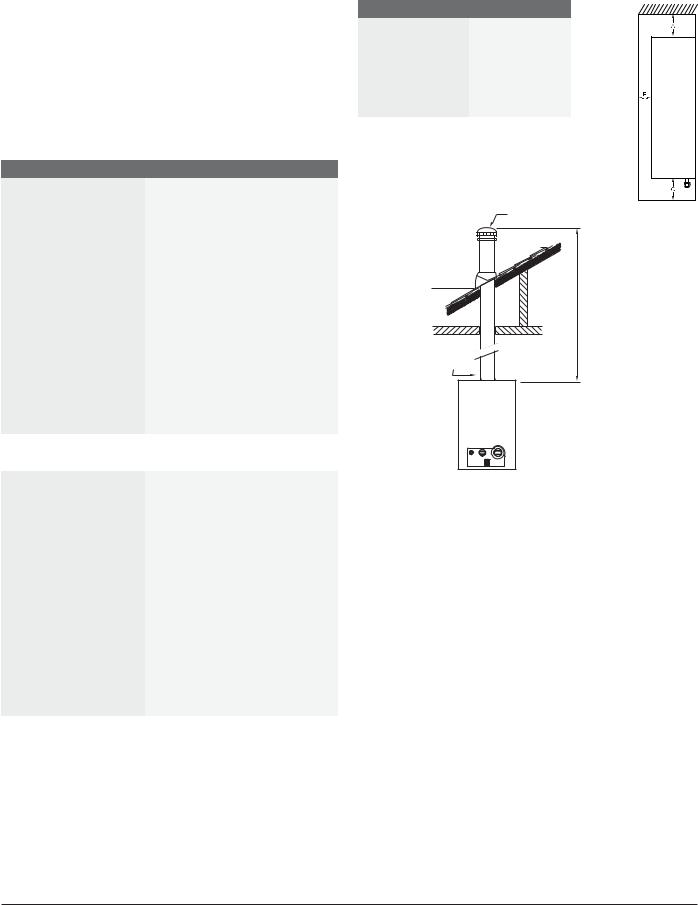
Fig. 2 Venting configuration
Installation guidelines:
Venting:
5" minimum diameter — do not reduce vent size Refer to installation manual for vent material options
Do not combination vent with any power vented appliances
Establish a one-foot rise before any elbows
Minimum vent height - 6 feet
Horizontal sections must slope upwards at least ¼" for every foot of the horizontal length and be properly supported
Gas piping:
Heater will not function properly without adequate supply gas pressure
Any appliance connector should be ¾" minimum diameter
Plumbing:
Install the included pressure relief valve and pipe to suitable drain Minimum piping diameter is ¾"
Do not solder directly to connections on the bottom of the unit Use full port ball valves for isolation valves
Application manual | 11.2007 |
Bosch Water Heating |
Applications manual |
| 13 |
|
|
2.9 Bosch GWH 425 PN
Features:
Standing pilot ignition 78% thermal efficiency
Endless hot water for one major application at a time
Modulating gas valve — constant temperature at varying flow rates Model GWH 425 PN N for natural gas (NG) supply
Model GWH 425 PN L for liquid propane (LP) supply 15-year warranty
GWH 425 PN Technical Specifications
Power input |
Natural Gas: 31,000 - 117,000 BTU |
|
|
|
LP Gas: 31,000 - 117,000 BTU |
|
|
Minimum flow to activate |
0.6 gallons per minute (gpm) |
Flow rates |
45˚F rise @ 4.2 gpm |
|
55˚F rise @ 3.4 gpm |
|
65˚F rise @ 2.9 gpm |
|
77˚F rise @ 2.4 gpm |
|
90˚F rise @ 2.1 gpm |
|
|
Thermal Efficiency |
NG: 78% LP: 78% |
|
|
Dimensions |
25.75" h x 16.75" w x 8.5" d |
|
|
Weight |
33 lbs. |
Modulating gas valve |
yes |
Ignition |
Standing pilot |
Accessories |
Horizontal vent kit (AQ4) - power |
|
vent kit for horizontal venting |
|
|
|
|
GWH 425 PN Installation Specifications |
|
Gas connection |
¾" Male NPT |
|
|
Water connections |
¾" Male NPT |
NG gas pressure |
Minimum: 7" W.C. |
|
Maximum: 14" W.C. |
|
|
LP gas pressure |
Minimum: 11" W.C. |
|
Maximum: 14" W.C. |
|
|
Water pressure |
Minimum: 30 PSI |
|
Maximum: 150 PSI |
|
|
Electrical supply |
120VAC - plugs in |
Vertical venting |
5" minimum diameter - natural |
|
draft |
|
|
Horizontal venting |
AQ4 horizontal vent kit required |
|
for horizontal terminations |
|
|
GWH 425 PN Installation Clearances
Top (A) |
12" |
|
|
Front (B) |
4" |
|
|
Back |
0" |
|
|
Sides |
4" |
|
|
Floor (C) |
12" |
|
|
LIS TED VE NT C AP
MINIMUM 6
FE ET (1.8M)
LIS TED G AS VE NT
E S TAB LIS H A ONE
F OOT R IS E B E F OR E
ANY E LB OW S
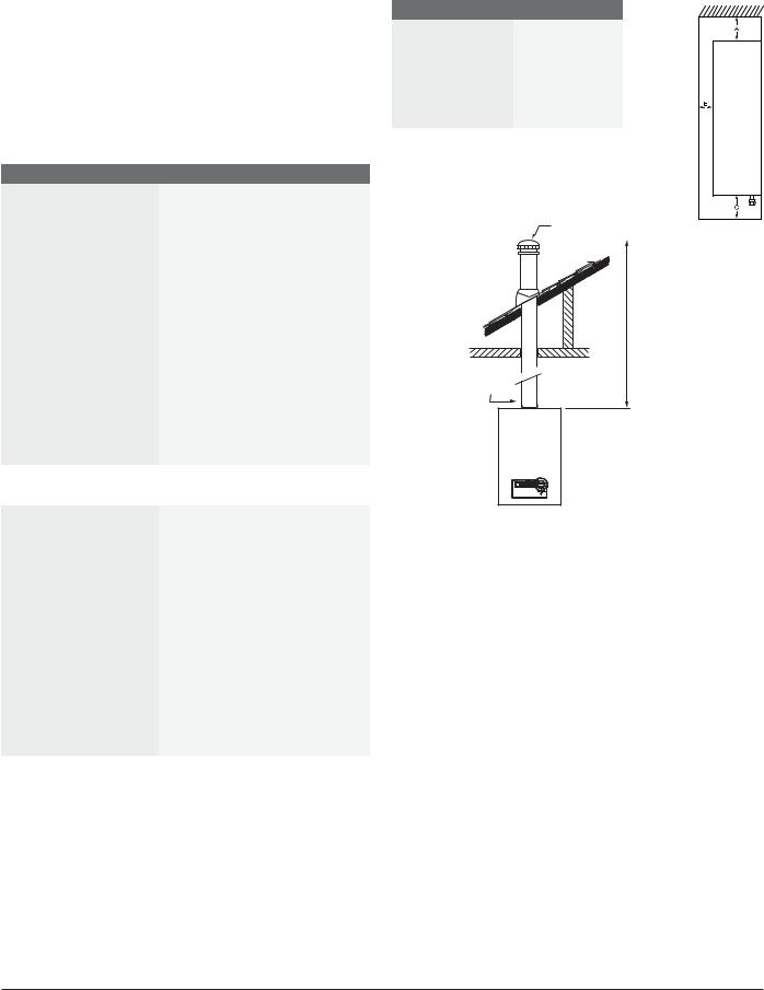
Fig. 4 Venting configuration
Installation guidelines:
Venting:
5" minimum diameter — do not reduce vent size. Refer to installation manual for vent material options
Do not combination vent with any power vented appliances.
Establish a one-foot rise before any elbows
Minimum vent height - 6 feet.
Horizontal sections must slope upwards at least ¼" for every foot of the horizontal length and be properly supported.
Gas piping:
Heater will not function properly without adequate supply gas pressure.
Any appliance connector should be ¾" minimum diameter
Plumbing:
Install the included pressure relief valve and pipe to suitable drain.
Minimum piping diameter is ¾".
Do not solder directly to the bottom of the unit. Use full port ball valves for isolation valves.
Bosch Water Heating |
Applications manual | 11.2007 |
1 4 | |
Applications manual |
|
|
2.10 Bosch GWH 260 PN
Features:
Standing pilot ignition 78% thermal efficiency
Mounts on wall for easy installation
Venting: 4" double wall B-vent — natural draft
Modulating gas valve — constant temperature at varying flow rates Model GWH 260 PN N for natural gas (NG) supply
Model GWH 260 PN L for liquid propane (LP) supply 15-year warranty
GWH 260 PN Installation Clearances
Top (A) |
12" |
|
|
Front (B) |
4" |
|
|
Back |
0" |
|
|
Sides |
4" |
|
|
Floor (C) |
12" |
|
|
GWH 260 PN Technical Specifications
Gas input |
Natural Gas: 30,735 - 74,900 BTU |
|
|
|
LP Gas: 30,735 - 74,900 BTU |
|
|
Minimum flow to activate |
0.6 gallons per minute (gpm) |
|
|
Flow rates |
45˚F rise @ 2.6 gpm |
|
55˚F rise @ 2.1 gpm |
|
65˚F rise @ 1.7 gpm |
|
77˚F rise @ 1.5 gpm |
|
90˚F rise @ 1.3 gpm |
|
|
Thermal Efficiency |
NG: 78% LP: 78% |
Dimensions |
28.8" h x 12.2" w x 8.5" d |
|
|
Weight |
25 lbs. |
|
|
Modulating gas valve |
yes |
|
|
Ignition |
Standing pilot |
|
|
|
|
GWH 260 PN Installation Specifications |
|
Gas connection |
¾" Male NPT |
|
|
Water connections |
¾" Male NPT |
|
|
NG gas pressure |
Minimum: 7" W.C. |
|
Maximum: 14" W.C. |
|
|
LP gas pressure |
Minimum: 11" W.C. |
|
Maximum: 14" W.C. |
|
|
Water pressure |
Minimum: 30 PSI |
(Static) |
Minimum well pressure: 40PSI |
|
Maximum: 150 PSI |
|
|
Electrical supply |
120VAC - plugs in |
|
|
Venting |
4" double wall B-vent - natural |
|
draft |
|
|
LIS TED VE NT C AP
MINIMUM 6
FE ET (1.8M)
LIS TED G AS VE NT
E S TAB LIS H A ONE
F OOT R IS E B E F OR E
ANY E LB OW S
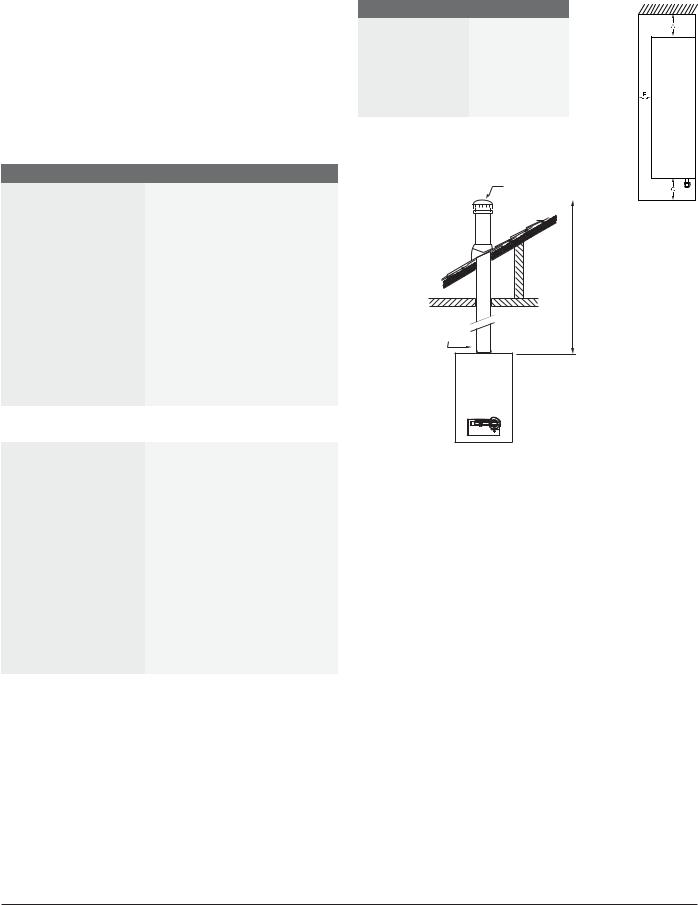
Fig. 4 Venting configuration
Installation guidelines:
Venting:
4" minimum diameter — do not reduce vent size. Refer to installation manual for vent material options
Do not combination vent with any power vented appliances.
Establish a one-foot rise before any elbows
Minimum vent height - 6 feet.
Horizontal sections must slope upwards at least ¼" for every foot of the horizontal length and be properly supported.
Gas piping:
Heater will not function properly without adequate supply gas pressure.
Any appliance connector should be ¾" minimum diameter
Plumbing:
Install the included pressure relief valve and pipe to suitable drain.
Minimum piping diameter is ¾".
Do not solder directly to the bottom of the unit. Use full port ball valves for isolation valves.
Application manual | 11.2007 |
Bosch Water Heating |

Applications manual |
| 15 |
|
|
2.11 Powerstream Pro RP17PT, RP27PT
Features:
Over 90% efficiency rating
10-year warranty on heat exchanger Durable polymer construction External temperature control knob Thermal cut-out for safety
Flow sensor to provide a constant output temperature Provides an ENDLESS supply of hot water
Weighs less than 25 pounds and fits virtually anywhere
No temperature/pressure relief valve necessary (unless required by local codes)
|
|
Technical Specifications |
|
|
Model |
RP17PT |
RP27PT |
|
|
|
|
Efficiency |
90% |
94% |
|
Dimensions |
15 ½" x 15 ¼" x 4 ½" |
15 ½" x 15 ¼" x 4 ½" |
|
|
Weight |
20 lbs. |
22 lbs. |
Water fittings |
¾" Male NPT |
¾" Male NPT |
|
|
|
|
|
Activation rate |
0.6 gpm |
0.8 gpm |
|
Electrical requirements |
|
||
|
Volts |
240 |
240 |
|
|
|
|
|
Kilowatts |
17.25kW |
26.85kW |
Amps |
U.S.A |
80 (2x40 amps) |
120 (3x40 amps) |
|
Canada |
80 (1x80 amps) |
120 (1x120amps) |
|
|
|
|
Wire |
U.S.A |
8 AWG |
8 AWG |
size |
|
(4 conductors & ground) |
(4 conductors & ground) |
|
Canada |
Check Canadian |
Check Canadian |
|
|
Electrical Code |
Electrical Code |
|
|
(C22.1-02) |
(C22.1-02) |
|
|
|
|
|
Phase |
Single |
Single |
Maximum flow rate at given temperature rise |
|||
45°F Rise |
2.6 gpm |
4.0 gpm |
|
|
|
|
|
50°F Rise |
2.3 gpm |
3.7 gpm |
|
|
|
|
|
60°F Rise |
2.0 gpm |
3.0 gpm |
|
|
|
|
|
70°F Rise |
1.7 gpm |
2.6 gpm |
|
|
|
|
|
80°F Rise |
1.5 gpm |
2.2 gpm |
|
Installation guidelines:
Electrical:
Minimum electrical service for RP17PT is 150 amps. Minimum electrical service for RP27PT is 200 amps. Minimum wire size for both models is 8 AWG.
Plumbing:
Do not solder directly to connections on the bottom of the unit. Use unions to facilitate easy future maintenance.
Use full port ball valves for isolation valves.
RP17PT terminal block
2 independent
40 amp double-pole circuit breakers
Fig. 5 RP17PT Electrical Connections
RP27PT terminal block
3 independent
40 amp double-pole circuit breakers
Fig. 6 RP27PT Electrical Connections
Bosch Water Heating |
Applications manual | 11.2007 |
 Loading...