


 BM 2610014415 01-11 E:BM 2610012089 12-10 E 1/10/11 7:17 AM Page 1
IMPORTANT: |
IMPORTANT : |
IMPORTANTE: |
Read Before Using |
Lire avant usage |
Leer antes de usar |
|
|
|
Operating/Safety Instructions 
 Consignes de fonctionnement/sécurité
Instrucciones de funcionamiento y seguridad
GTS1031
|
|
|
|
Call Toll Free for Con- |
Pour obtenir des informations |
Llame gratis para |
|
sumer Information |
et les adresses de nos centres |
obtener información |
|
& Service Locations |
de service après-vente, |
para el consumidor y |
|
|
|
appelez ce numéro gratuit |
ubicaciones de servicio |
1-877-BOSCH99 (1-877-267-2499) www.boschtools.com
For English Version |
Version française |
Versión en español |
See page 2 |
Voir page 37 |
Ver la página 72 |
|
|
|
 BM 2610014415 01-11 E:BM 2610012089 12-10 E 1/10/11 7:17 AM Page 2
|
general Safety Rules |
|
“READ ALL INSTRUCTIONS” Failure to follow the safety rules listed below and other basic |
! WARNING |
|
|
safety precautions may result in serious personal injury. |
|
Work Area
KEEp CHIldREN AWAy
Do not let visitors contact tool or extension cord. All visitors should be kept away from work area.
KEEp WORK AREAS ClEAN
Cluttered areas and benches invite accidents.
MAKE WORKSHOp CHIld-pROOf
With padlocks, master switches.
AVOId dANgEROUS ENVIRONMENTS
Don’t use power tools in damp or wet locations. Keep work area well lit. Do not expose power tools to rain. Do not use tool in presence of flammable liquids or gases.
personal Safety
KNOW yOUR pOWER TOOl
Read and understand the owner’s manual and labels affixed to the tool. Learn its application and limitations as well as the specific potential hazards peculiar to this tool.
dON’T OVERREACH
Keep proper footing and balance at all times.
Stay alert. Watch what you are doing. Use common sense. Do not operate tool when you are tired. Do not operate while under medication or while using alcohol or other drug.
dRESS pROpERly
Do not wear loose clothing or jewelry. They can be caught in moving parts. Rubber gloves and non-skid footwear are recommended when working outdoors. Wear protective hair covering to contain long hair.
USE SAfETy gOgglES
Also face or dust mask if cutting operation is dusty, and ear plugs during extended periods of operation.
gUARd AgAINST ElECTRIC SHOCK
Prevent body contact with grounded surfaces. For example: pipes, radiators, ranges, refrigerator enclosures.
dISCONNECT TOOl fROM pOWER SOURCE
When not in use, before servicing, when changing blades, bits, cutters, etc.
KEEp gUARdS IN plACE
In working order, and in proper adjustment and alignment.
REMOVE AdjUSTINg KEyS ANd WRENCHES
When not in use, before servicing, when changing blades, bits, cutters, etc.
AVOId ACCIdENTAl STARTINg
Make sure the switch is in the “OFF” position before plugging in tool.
NEVER STANd ON TOOl OR ITS STANd
Serious injury could occur if the tool is tipped or if the cutting tool is accidentally contacted. Do not store materials on or near the tool such that it is necessary to stand on the tool or its stand to reach them.
CHECK dAMAgEd pARTS
Before further use of the tool, a guard or other part that is damaged should be carefully checked to ensure that it will operate properly and perform its intended function. Check for alignment of moving parts, mounting and any other conditions that may affect its operation. A guard or other part that is damaged should be properly replaced.
All repairs, electrical or mechanical, ! WARNING should be attempted only by
trained repairmen. Contact the nearest Bosch Factory Service Center, Authorized Service Station or other competent repair service.
|
|
Use only Bosch replacement parts; |
! |
WARNING |
|
|
|
any others may create a hazard. |
|
|
|
|
|
Use only accessories that are rec- |
! |
WARNING |
|
|
|
ommended by the manufacturer for |
|
|
your model. Accessories that may be suitable for one tool, may become hazardous when used on another tool.
Tool Use dON’T fORCE TOOl
It will do the job better and safer at the rate for which it was designed.
USE THE RIgHT TOOl
Don’t force small tool or attachment to do the job of a heavy-duty tool. Don’t use tool for purpose not intended — for example; don’t use circular saw for cutting tree limbs or logs.
SECURE WORK
Use clamps or a vise to hold work. It’s safer than using your hand and it frees both hands to operate the tool.
“SAVE THESE INSTRUCTIONS”
-2-
 BM 2610014415 01-11 E:BM 2610012089 12-10 E 1/10/11 7:17 AM Page 3
Additional Safety Rules
dIRECTION Of fEEd
Feed work into a blade or cutter against the direction of rotation of the blade or cutter only.
NEVER lEAVE TOOl RUNNINg UNATTENdEd
Turn power off. Don’t leave tool until it comes to a complete stop.
Tool Care
dO NOT AlTER OR MISUSE TOOl
These tools are precision built. Any alteration or modification not specified is misuse and may result in dangerous conditions.
AVOId gASEOUS AREAS
Do not operate electric tools in gaseous or explosive atmospheres. Motors in these tools normally spark, and may result in a dangerous condition.
MAINTAIN TOOlS WITH CARE
Keep tools sharp and clean for better and safer performance. Follow instructions for lubricating and changing accessories. Inspect tool cords periodically and if damaged, have repaired by authorized service facility. Inspect extension cords periodically and replace if damaged. Keep handles dry, clean and free from oil and grease.
Before connecting the tool to a power source (receptacle, outlet, etc.), be sure voltage supplied is the same as that
specified on the nameplate of the tool. A power source with voltage greater than that specified for the tool can result in serious injury to the user — as well as damage to the tool. If in doubt, DO NOT PLUG IN THE TOOL. Using a power source with voltage less than the nameplate rating is harmful to the motor.
For your own safety, do not operate ! WARNING your table saw until it is completely
assembled and installed according to the instructions … and until you have read and understood the following:
1.General Safety Rules. . . . . . . . . . . . . . . . . . 2–5
2.Double Insulated Tools . . . . . . . . . . . . . . . . . . . 6
3.Getting To Know Your Table Saw. . . . . . . . 9, 10
4.Assembly . . . . . . . . . . . . . . . . . . . . . . . . . 12–16
5.Adjustments . . . . . . . . . . . . . . . . . . . . . . . 17–21
6.Basic Table Saw Operation . . . . . . . . . . . 22–34
7.Maintaining Your Table Saw. . . . . . . . . . . 34–35
7. STAbIlITy Of SAW
Your table saw MUST BE BOLTED securely to a stand or workbench. In addition, if there is any tendency for the table saw to tip over or move during certain operations such as cutting long, heavy boards, use an auxiliary support.
8. lOCATION
Use the table saw in a well lit area and on a level surface, clean and smooth enough to reduce the risk of trips and falls. Use it where neither the operator nor the casual observer is forced to stand in line with the blade.
9. KICKbACK
Kickbacks can cause serious injury: A “KICKBACK” occurs when a part of the workpiece binds between the sawblade and the rip fence or other fixed object. Workpiece binding the blade due to misalignment, can also cause kickback. During kickback, workpiece rises from table and is thrown toward the operator. Keep your face and body to one side of the sawblade, out of line with a possible “KICKBACK”.
KICKbACKS ANd pOSSIblE INjURy CAN
USUAlly bE AVOIdEd by:
a.Maintaining the rip fence parallel to the sawblade.
b.Keeping the sawblade sharp. Replacing or sharpening anti-kickback pawls when points become dull.
c.Keeping sawblade guard, spreader and anti-kick- back pawls in place and operating properly. The spreader must be in alignment with the sawblade and the pawls must stop a kickback once it has started. Check their action before ripping.
d.NOT ripping workpiece that is twisted or warped or does not have a straight edge to guide along the rip fence.
e.NOT releasing work until you have pushed it all the way past the sawblade.
f.Using a Push Stick for ripping widths of 2" to 6" and an auxiliary fence and Push Block for ripping widths narrower than 2" (See “Basic Saw Operation, Using The Rip Fence” section, pages 29, 30).
g.NOT confining the cut-off piece when ripping or crosscutting.
h.When ripping, apply the feed force to the section of the workpiece between the sawblade and the rip fence. Use Push Stick or Push Block when appropriate (See item f. above).
“SAVE THESE INSTRUCTIONS”
-3-

 BM 2610014415 01-11 E:BM 2610012089 12-10 E 1/10/11 7:17 AM Page 4
Additional Safety Rules
10. pROTECTION:
Eyes, hands, face, ears and body.
! |
WARNING |
TO AVOId bEINg pUllEd |
|
|
INTO THE SpINNINg TOOl, |
|
|
|
dO NOT WEAR: loose fitting gloves |
||
|
|
loose Clothing |
|
|
Necktie, jewelry |
dO: |
TIE bACK lONg HAIR |
|
|
ROll lONg SlEEVES AbOVE |
|
|
ElbOWS |
|
a.If any part of your saw is missing, malfunctioning, has been damaged or broken … such as the motor switch, or other operating control, a safety device or the power cord … cease operating immediately until the particular part is properly repaired or replaced.
b.Wear safety goggles and a face shield if operation is dusty. Wear ear plugs or muffs during extended periods of operation. Small loose pieces of wood or other objects that contact the rear of the revolving blade can be thrown back at the operator at excessive speed. This can usually be avoided by keeping the guard and spreader in place for all “THRU-SAW- ING” operations (sawing entirely thru the work) AND by removing all loose pieces from the table with a long stick of wood IMMEDIATELY after they are cut off.
c.Use extra caution when the guard assembly is removed for resawing, dadoing, rabbeting or molding
— replace the guard as soon as that operation is completed.
d.NEVER turn the saw “ON” before clearing the table of all tools, wood scraps, etc., except the workpiece and related feed or support devices for the operation planned.
e.NEVER place your face or body in line with the cutting tool.
•NEVER place your fingers and hands in the path of the sawblade or other cutting tool.
•NEVER reach in back of the cutting tool with either hand to hold down or support the workpiece, remove wood scraps, or for any other reason. Avoid awkward operations and hand positions where sudden slip could cause fingers or hand to move into a sawblade or other cutting tool.
•DO NOT perform any operation “FREEHAND” — always use either the rip fence or the miter gauge to position and guide the work.
•NEVER use the rip fence when crosscutting or the miter gauge when ripping. DO NOT use the rip fence as a length stop.
•NEVER hold onto or touch the “free end” of the workpiece or a “free piece” that is cut off, while power is “ON” and/or the sawblade is rotating.
•Shut “OFF” the saw and disconnect the power cord when removing the table insert, changing the cutting tool, removing or replacing the blade guard, or making adjustments.
•Provide adequate support to the rear and sides of the saw table for wider or long workpieces.
•Plastic and composition (like hardboard) materials may be cut on your saw. However, since these are usually quite hard and slippery, the anti-kickback pawls may not stop a kickback. Therefore, be especially attentive to following proper set-up and cutting procedures for ripping. Do not stand, or permit anyone else to stand, in line with a potential kickback.
f.If you stall or jam the sawblade in the workpiece, turn saw “OFF”, remove the workpiece from the sawblade, and check to see if the sawblade is parallel to the table slots or grooves and if the spreader is in proper alignment with the sawblade. If ripping at the time, check to see if rip fence is parallel with the sawblade. Readjust as indicated.
g.NEVER gang crosscut — lining up more than one workpiece in front of the blade (stacked vertically, or horizontally outward on the table) and then pushing thru sawblade. The blade could pick up one or more pieces and cause a binding or loss of control and possible injury.
h.DO NOT remove small pieces of cut-off material that may become trapped inside the blade guard while the saw is running. This could endanger your hands or cause a kickback. Turn saw “OFF” and wait until blade stops.
i.Do not reach beyond table saw base. Keep your hands away from spinning blade.
11. KNOW yOUR CUTTINg TOOlS
Dull, gummy or improperly sharpened or set cutting tools can cause material to stick, jam, stall the saw, or kickback at the operator. Minimize potential injury by proper cutting tool and machine maintenance. NEVER ATTEMPT TO FREE A STALLED SAWBLADE WITHOUT FIRST TURNING THE SAW OFF.
“SAVE THESE INSTRUCTIONS”
-4-

 BM 2610014415 01-11 E:BM 2610012089 12-10 E 1/10/11 7:17 AM Page 5
Additional Safety Rules
a.NEVER use grinding wheels, abrasive cut-off wheels, friction wheels (metal slitting blades) wire wheels or buffing wheels.
b.USE ONLY RECOMMENDED ACCESSORIES.
c.Crosscutting operations are more conveniently worked and with greater safety if an auxiliary wood facing is attached to the miter gauge. (See Page 26).
d.Make sure the top of the cutting tool rotates toward you when standing in normal operating position. Also make sure the cutting tool, arbor collars and arbor nut are installed properly. Keep the cutting tool as low as possible for the operation being performed. Keep all guards in place whenever possible.
• Do not use any blade or other cutting tool marked for an operating speed less than 5000 R.P.M. Never use a cutting tool larger in diameter than the diameter for which the saw was designed. For greatest safety and efficiency when ripping, use the maximum diameter blade for which the saw is designed, since under these conditions the spreader is nearest the blade.
e. Make sure the table insert is flush or slightly below the table surface on all sides except for rear side. NEVER operate the saw unless the proper insert is installed.
12. THINK SAfETy
SAFETY IS A COMBINATION OF OPERATOR COMMON SENSE AND ALERTNESS AT ALL TIMES WHEN THE TABLE SAW IS BEING USED.
Do not allow familiarity (gained from frequent use of your table saw) to become commonplace. Always remember that
a careless fraction of a second is sufficient to inflict severe injury.
The operation of any power tool can result in foreign objects being thrown into the
eyes, which can result in severe eye damage. Always wear safety goggles that com-
ply with ANSI Z87.1 (shown on package) before commencing power tool operation.
! WARNING Some dust created by power sanding, sawing, grinding,
drilling, and other construction activities contains chemicals known to cause cancer, birth defects or other reproductive harm. Some examples of these chemicals are:
•Lead from lead-based paints,
•Crystalline silica from bricks and cement and other masonry products, and
•Arsenic and chromium from chemically treated lumber.
Your risk from these exposures varies, depending on how often you do this type of work. To reduce your exposure to these chemicals: work in a well ventilated area, and work with approved safety equipment, such as those dust masks that are specially designed to filter out microscopic particles.
NOTE ANd fOllOW SAfETy INSTRUCTIONS
THAT AppEAR ON THE fRONT Of yOUR
TAblE SAW.
“SAVE THESE INSTRUCTIONS”
-5-
 BM 2610014415 01-11 E:BM 2610012089 12-10 E 1/10/11 7:17 AM Page 6
double Insulated Tools
Double insulation 


 is a design concept used in electric power tools which eliminates the need for the three wire grounded power cord and grounded power supply system. It is a recognized and approved system by Underwriter’s Laboratories, CSA and Federal OSHA authorities.
IMpORTANT: Servicing of a tool with double insulation requires care and knowledge of the system and should be performed only by a qualified service technician.
WHEN SERVICING, USE ONLY IDENTICAL REPLACEMENT PARTS.
POLARIZED PLUGS. To reduce the risk of electrical shock, your tool is equipped with a polarized plug (one blade is wider than the other), this plug will fit in a polarized outlet only one way. If the plug does not fit fully in the outlet, reverse the plug. If it still does not fit, contact a qualified electrician to install the proper outlet. To reduce the risk of electrical shock, do not change the plug in any way.
EXTENSION CORdS
Replace damaged cords immedi- ! WARNING ately. Use of damaged cords can
shock, burn or electrocute.
If an extension cord is necessary, a cord with adequate size conductors should be used to prevent excessive voltage drop,
loss of power or overheating. The table shows the correct size to use, depending on cord length and nameplate amperage rating of tool. If in doubt, use the next heavier gauge. Always use U.L. and CSA listed extension cords.
RECOMMENdEd SIZES Of EXTENSION CORdS 120 VOlT AlTERNATINg CURRENT TOOlS
Tool’s |
Cord Size in A.W.g. |
Wire Sizes in mm2 |
|||||||
Ampere |
Cord length in feet |
Cord length in Meters |
|||||||
Rating |
25 |
50 |
100 |
150 |
15 |
30 |
60 |
120 |
|
3-6 |
|
|
|
|
|
|
|
|
|
|
18 |
16 |
16 |
14 |
0.75 |
0.75 |
1.5 |
2.5 |
|
6-8 |
|
18 |
16 |
14 |
12 |
0.75 |
1.0 |
2.5 |
4.0 |
8-10 |
|
18 |
16 |
14 |
12 |
0.75 |
1.0 |
2.5 |
4.0 |
10-12 |
|
16 |
16 |
14 |
12 |
1.0 |
2.5 |
4.0 |
— |
12-16 |
|
14 |
12 |
— |
— |
— |
— |
— |
— |
|
|
|
|
|
|
|
|
|
|
NOTE: The smaller the gauge number, the heavier the cord.
“SAVE THESE INSTRUCTIONS”
Table of Contents
Page
General Safety Rules . . . . . . . . . . . . . . . . . . . . .2
Additional Safety Rules . . . . . . . . . . . . . . . . .3–5
Double Insulated Tools & Extension Cords . . . .6
Table of Contents . . . . . . . . . . . . . . . . . . . . . .6-7
Glossary of Terms . . . . . . . . . . . . . . . . . . . . . .7-8
Tools Needed For Assembly . . . . . . . . . . . . . . .8
Getting To Know Your Table Saw . . . . . . . . .9, 10
Power Switch . . . . . . . . . . . . . . . . . . . . . . . . .9
Elevation Wheel . . . . . . . . . . . . . . . . . . . . . .9
Blade Bevel Lock Handle . . . . . . . . . . . . . . .9
Blade Bevel Scale . . . . . . . . . . . . . . . . . . . . .9
Base . . . . . . . . . . . . . . . . . . . . . . . . . . . . . . .9
Table Extension Lock Handle . . . . . . . . . . . .9
Push Stick . . . . . . . . . . . . . . . . . . . . . . . . . . .9
Table Extension . . . . . . . . . . . . . . . . . . . . . . .9
Rip Fence . . . . . . . . . . . . . . . . . . . . . . . . . . .9
Rip Fence Scale . . . . . . . . . . . . . . . . . . . . . .9
Smart Guard System . . . . . . . . . . . . . . . . . .9
Page Table Insert . . . . . . . . . . . . . . . . . . . . . . . . . .9 Table . . . . . . . . . . . . . . . . . . . . . . . . . . . . . .10 Miter Gauge . . . . . . . . . . . . . . . . . . . . . . . . .10 Cord Wrap . . . . . . . . . . . . . . . . . . . . . . . . . .10 Rip Fence Storage . . . . . . . . . . . . . . . . . . .10 Push Stick & Wrench Storage . . . . . . . . . .10 One-Handed Carry Handle . . . . . . . . . . . . .10 Smart Guard System Storage . . . . . . . . . .10 Dust Port/Vacuum Hook-Up . . . . . . . . . . . .10 Anti-Kickback Device Storage . . . . . . . . . .10 Miter Gauge Storage . . . . . . . . . . . . . . . . . .10 Hex Wrench & Storage compartment . . . .10 Stand Attachment Bracket . . . . . . . . . . . . .10
Unpacking and Checking Contents . . . . . . . . .11 Table of Loose Parts . . . . . . . . . . . . . . . . . .11 Assembly . . . . . . . . . . . . . . . . . . . . . . . . . .12–16
Attaching Smart Guard
System Components . . . . . . . . . . . . . .12, 13
-6-

 BM 2610014415 01-11 E:BM 2610012089 12-10 E 1/10/11 7:17 AM Page 7
Page Changing The Blade . . . . . . . . . . . . . . .14-15 Attaching The Rip Fence for Use
& Storage . . . . . . . . . . . . . . . . . . . . . . . . . .16 Mounting Table Saw to Workbench . . . . . . . . .16 Adjustments . . . . . . . . . . . . . . . . . . . . . . . .17–21 Adjusting 0 & 45 Degree Positive Stops . . .17
Adjusting Blade Parallel to the
Slot Miter Gauge . . . . . . . . . . . . . . . . . . . . .18 Aligning Rip Fence . . . . . . . . . . . . . . . . . . .19 Rip Fence Pointer Adjustment . . . . . . . . . .19 Table Pointer Adjustment . . . . . . . . . . . . . .20 Adjusting Riving Knife . . . . . . . . . . . . . .20-21 Adjusting Table insert . . . . . . . . . . . . . . . . .21
Basic Table Saw Operation . . . . . . . . . . . .22–34 Safety Power Switch . . . . . . . . . . . . . . . . . .22 Smart Guard System . . . . . . . . . . . . . .22, 23 Blade Bevel Control . . . . . . . . . . . . . . . . . .24 Extending Table Extension . . . . . . . . . . . . .24 Using Rip Fence Pointer . . . . . . . . . . . . . . .24
Page
Using Table Pointer . . . . . . . . . . . . . . . . . . .24
Work Helpers . . . . . . . . . . . . . . . . . . . . . . . .25
Using the Miter Gauge . . . . . . . . . . . . . . . .26
Crosscutting . . . . . . . . . . . . . . . . . . . . . . . .27
Repetitive Crosscutting . . . . . . . . . . . . . . . .28
Miter Cutting . . . . . . . . . . . . . . . . . . . . . . . .28
Bevel Crosscutting . . . . . . . . . . . . . . . . . . .28
Compound Miter Cutting . . . . . . . . . . . . . . .28
Using the Rip Fence . . . . . . . . . . . . . . .29, 31
Ripping . . . . . . . . . . . . . . . . . . . . . . . . . . . .30
Non Thru-Sawing . . . . . . . . . . . . . . . . . . . .31
Rabbeting . . . . . . . . . . . . . . . . . . . . . . . . . .31
Dadoing Cutting . . . . . . . . . . . . . . . . . . .32-33
Maintaining Your Table Saw . . . . . . . . . . . . . . .34
Clearing Dust Chute/ Scoop . . . . . . . . . . . .34
Lubrication . . . . . . . . . . . . . . . . . . . . . . . . . .35
Accessories . . . . . . . . . . . . . . . . . . . . . . . . . . .35
Trouble Shooting . . . . . . . . . . . . . . . . . . . . . . .36
glossary of Terms
WORKpIECE
The item on which the cutting operation is being performed. The surfaces of a workpiece are commonly referred to as faces, ends and edges.
ANTI-KICKbACK pAWlS
Device which, when properly maintained, is designed to stop the workpiece from being kicked back at the operator during operation.
ARbOR
The shaft on which a cutting tool is mounted.
bEVEl
Blade angle relative to the table surface.
CROSSCUT
A cutting or shaping operation made across the width of the workpiece cutting the workpiece to length.
dAdO
A non-through cut which produces a square sided notch or trough in the workpiece.
fEATHERbOARd
A device which can help guide workpieces during rip type operation by keeping workpiece in contact with
the rip fence. It also helps prevent kickback.
fREEHANd
Performing a cut without a fence, miter gauge, fixture, hold down or other proper device to keep the workpiece from twisting during the cut.
gUM
A sticky, sap-based residue from wood products. After it has hardened, it is referred to as “RESIN”.
HEEl
Misalignment of the blade which causes the trailing or outfeed side of the blade to contact the cut surface of the workpiece. Heel can cause kickback, binding, excessive force, burning of the workpiece or splintering. In general, heel creates a poor quality cut and can be a safety hazard.
KERf
The space in the workpiece where the material was removed by the blade.
KICKbACK
An uncontrolled grabbing and throwing of the workpiece back toward the front of the saw during a rip type operation.
-7-
 BM 2610014415 01-11 E:BM 2610012089 12-10 E 1/10/11
lEAdINg ENd
The end of the workpiece which, during a rip type operation, is pushed into the cutting tool first.
MOldINg
A non-through cut which produces a special shape in the workpiece used for joining or decoration.
NON THRU-SAWINg
Any cutting operation where the blade does not extend through the workpiece (e.g. Dado, Rabbet).
pUSH STICK
A device used to feed the workpiece through the saw during narrow ripping-type operation and helps keep the operator’s hands well away from the blade. Use the Push Stick for rip widths less than 6 inches and more than 2 inches.
7:17 AM Page 8
pUSH blOCK
A device used for ripping-type operations too narrow to allow use of a Push Stick. Use a Push Block for rip widths less than 2 inches.
RAbbET
A notch in the edge of a workpiece. Also called an edge dado.
RIppINg
A cutting operation along the length of the workpiece cutting the workpiece to width.
REVOlUTIONS pER MINUTE (R.p.M.)
The number of turns completed by a spinning object in one minute.
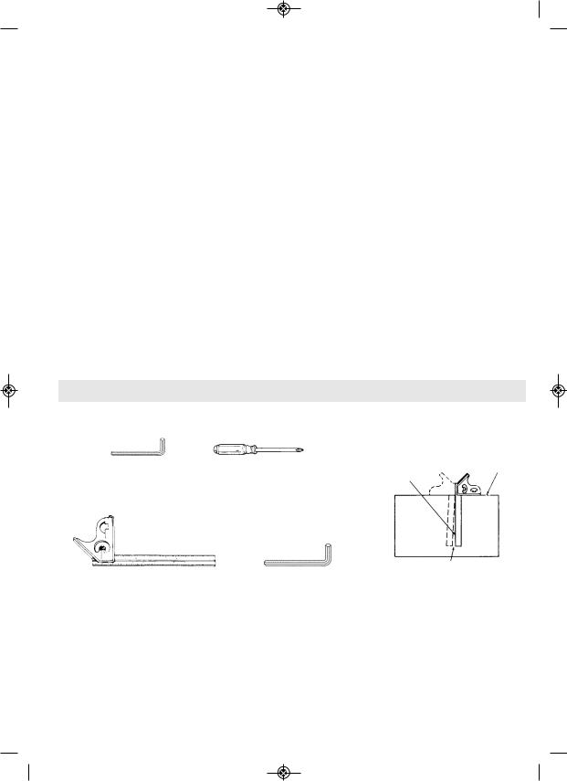
Tools Needed for Assembly And Adjustment
COMBINATION SQUARE MUST BE TRUE
|
|
|
STRAIGHT EDGE OF BOARD |
|
|
|
3/4" THICK. THIS EDGE |
|
|
DRAW LIGHT LINE ON |
MUST BE PERFECTLY |
HEX “L” WRENCH |
PHILLIPS SCREWDRIVER |
STRAIGHT. |
|
(Supplied-Insert Plate) |
|
BOARD ALONG THIS EDGE. |
|
2 MM
|
|
SHOULD BE NO GAP OR OVERLAP |
COMBINATION SQUARE |
HEX “L” WRENCH |
HERE WHEN SQUARE IS FLIPPED |
|
(Supplied-Tool Adjustment) |
OVER IN DOTTED POSITION. |
|
5 MM |
|
! WARNING |
Disconnect plug from power source before performing any assembly, adjustment or repair |
|
to avoid possible injury. |
|
-8-
 BM 2610014415 01-11 E:BM 2610012089 12-10 E 1/10/11 7:17 AM Page 9
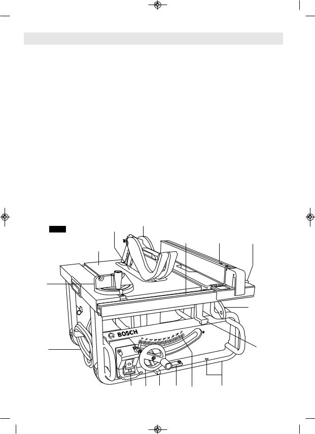
getting To Know your Table Saw
1. pOWER SWITCH
Switch incorporates hole for use with padlock to prevent accidental starting.
2. ElEVATION WHEEl
Elevates or lowers the blade. Also used to tilt the blade 0 to 45 degrees.
3.blAdE bEVEl lOCK HANdlE
Locks the blade to desired bevel angle.
4.blAdE bEVEl SCAlE
Shows the degree the blade is tilted.
5. bASE
Supports table saw. Holes are provided in base to bolt the saw to a workbench or stand. Includes integrated carry and adjustment handles
6. TAblE EXTENSION lOCK HANdlE
Allows you to lock the table extension at desired distances. Also prevents use of table saw with unlocked extension.
7. pUSH STICK
Allows you to rip smaller pieces of stock with a greater level of safety.
8. TAblE EXTENSION
Provides a larger work surface for wider workpieces.
9. RIp fENCE
Exclusive Self-Aligning, Squarelock rip fence can be easily moved or locked in place by simply raising or lowering lock handle.
10. RIp fENCE SCAlE
Shows the distance from the blade to rip fence through a convenient viewing and magnifying window. Lower portion of scale can be used up to 10 inches. Upper portion of scale is used for cuts beyond 10 inches.
11. SMART gUARd SySTEM
Consists of three key elements: Adjustable (3 position) Riving Knife, Anti-Kickback Device, and Barrier Guard Device. All of these are part of a modular system that requires no tools to assemble or unassemble. This Guard System must always be in place and working properly for all thru-sawing cuts.
12. TAblE INSERT
Removable for removing or installing blade or other cutting tools.
FIG. 1 |
12 |
11 |
|
|
|
|
|
||
|
13 |
10 |
9 |
8 |
|
|
|
|
|
14 |
|
|
|
|
|
|
|
|
7 |
15 |
|
|
|
6 |
1 |
2 |
3 |
24 |
4 |
5 |
-9-
 BM 2610014415 01-11 E:BM 2610012089 12-10 E 1/10/11 7:17 AM Page 10
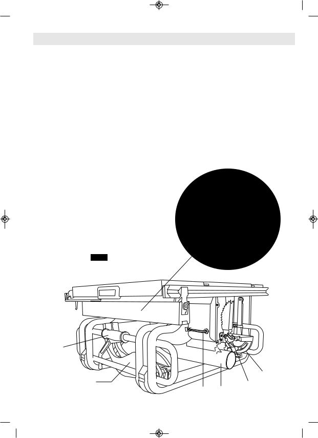
getting To Know your Table Saw
13. TAblE
Provides large working surface to support workpiece.
14. MITER gAUgE
Head can be locked in desired position for crosscutting or mitering by tightening the lock knob. ALWAYS SECURELY LOCK IT WHEN IN USE.
15. CORd WRAp
Allows you to easily secure the cord so it’s out of the way when transporting or storing.
16. RIp fENCE STORAgE
Conveniently stores rip fence when not in use.
17. pUSH STICK & WRENCH STORAgE
Allows you to store Push-stick and arbor wrenches
(2).
18. ONE-HANdEd CARRy HANdlE
Optimized position to carry tool at side with one hand.
19. SMART gUARd SySTEM STORAgE
When not in use, the Main Barrier Guard Device can be stored on the right side of the saw, underneath the table. The Anti-kickback Device stores just above the Dust Chute on the back of the tool.
20. dUST pORT/VACUUM HOOK-Up
Removable; to clear large pieces of wood trapped inside. Always check to ensure dust port is securely
FIG. 2
16 
18
19
fastened to table saw before use. Attach 2-1/4” vacuum hose into dust port for convenient sawdust removal. An adaptor is available for use with alternate hose sizes.
21.ANTI-KICKbACK dEVICE STORAgE
Conveniently stores Anti-Kickback Device when not in use.
22.MITER gAUgE STORAgE
Conveniently stores miter gauge when not in use.
23.HEX WRENCH & STORAgE COMpARTMENT
Hex wrench for removing lower dust chute and adjusting various hex heads on the saw.
24.STANd ATTACHMENT bRACKET
Quick connect attachment point for folding leg table saw stand.
17
22
21
23 20
-10-
 BM 2610014415 01-11 E:BM 2610012089 12-10 E 1/10/11 7:17 AM Page 11
Unpacking And Checking Contents
To avoid injury from unexpected starting or electrical shock during unpacking and setting up, do not plug the power
cord into a source of power. This cord must remain unplugged whenever you are working on the table saw.
Model GTS1031 Table Saw is shipped complete in one carton.
Separate all parts from packing materials and check each one with the illustration and the list of Loose Parts to make certain all items are accounted for before discarding any packing material (Fig. 3).
! WARNING If any parts are missing, do not attempt to assemble the table saw,
plug in the power cord or turn the switch on until the missing parts are obtained and are installed correctly.
FIG. 3 |
4 |
5 |
7 |
|
6
 2 3
2 3
|
TAblE Of lOOSE pARTS |
|
|
|
ITEM |
DESCRIPTION |
QTY. |
|
|
1 |
Table Saw Assembly |
1 |
1 |
|
2 |
Rip Fence |
1 |
|
|
3 |
Table Insert |
1 |
|
|
4 |
Barrier Guard Assembly |
1 |
FIG. 4 |
|
5 |
Anti-Kickback Device |
1 |
||
|
||||
6 |
Miter Gauge |
1 |
|
|
7 |
Push Stick |
1 |
|
NOTE: Cut cable tie 8 (for shipping purpose only) located between the saw base and under carriage (Fig. 4). You may cause damage to the blade elevation system if trying to raise blade if cable tie is not removed.
8
-11-

 BM 2610014415 01-11 E:BM 2610012089 12-10 E 1/10/11 7:17 AM Page 12
Assembly
ATTACHINg THE SMART gUARd SySTEM
! WARNING |
To prevent personal injury, always |
|
disconnect plug from power source |
before attaching or removing the Smart Guard |
|
System. |
|
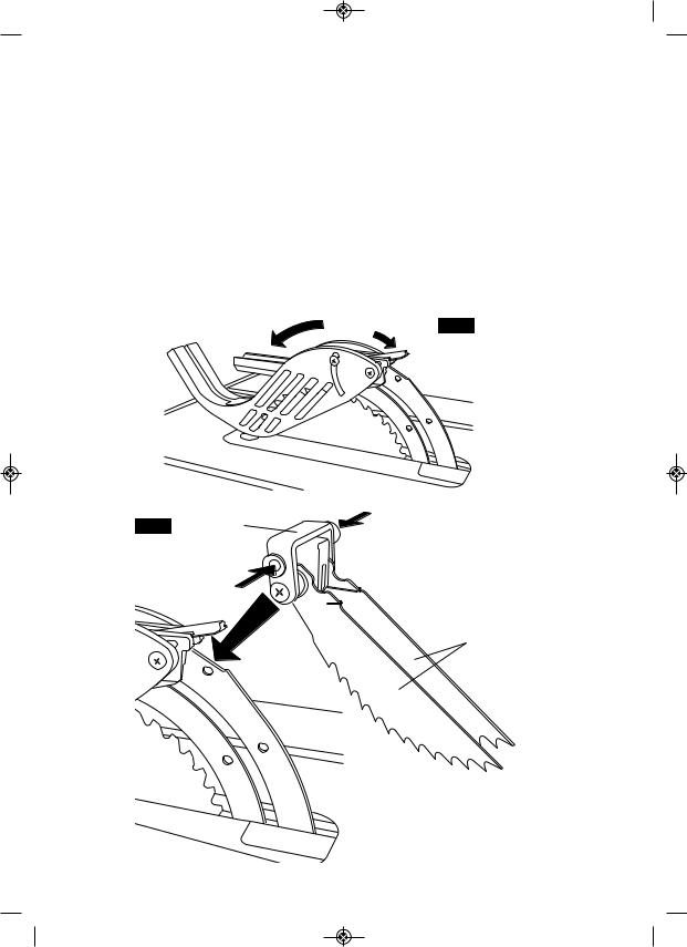
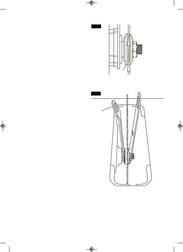
pOSITIONINg THE RIVINg KNIfE
1.Remove table insert using finger hole.
2.Raise the blade as high as it will go and set it perpendicular to table (0° on bevel scale) (Fig. 5).
3.Rotate the riving knife release lever 1 clockwise, so that it points upward (Fig. 5).
4.Pull riving knife 2 towards release lever to disengage it from the pins 3.
5.Slide the riving knife 2 up to its highest position, so that it is directly over the center of the blade (Fig. 6).
6.Align holes in riving knife with pins 3 and lock the release lever 1 by rotating it counterclockwise. Push/pull riving knife to verify that it is locked in place (Fig. 6).
7.Replace table insert (Fig. 7).
ATTACHINg THE gUARd ASSEMbly
8.With one hand, hold the front of the barrier guard assembly 4 by the metal “fork”. With the other hand, hold the guard release lever 5 up (Fig. 7).
9.Lower the rear of guard assembly and slip the cross bar 6 into the rear notch 7 on top of the riving knife 2 (Fig. 7).
4
5
FIG. 5
2
1
2 |
FIG. 6 |
|
3
1
 FIG. 7
 2
2
7 6
-12-
 BM 2610014415 01-11 E:BM 2610012089 12-10 E 1/10/11 7:17 AM Page 13
10.Lower the front of the guard assembly 4 until the metal “fork” is parallel with the table (Fig. 8).
11.Press down on the guard release lever 5 until you feel and hear it snap into the locking position. Check that the guard assembly is securely connected (Fig. 8).
ATTACHINg THE ANTI-KICKbACK dEVICE
12.Attach the Anti-Kickback Device 7 into the flat recessed area 8 of the riving knife 2 (Fig. 9).
13.Squeeze the compression pads 9 while nesting the device into the flat area (Fig. 9).
14.Release the compression pads such that the Anti-Kickback Device locks onto the riving knife
immediately behind the guard assembly. Check that the attachment pin is securely connected into locking hole. Carefully raise and lower the pawls 10 – when letting go, the spring-loaded pawls must come down and contact the table insert (Fig. 9).
Hint: Position the Anti-Kickback Device behind the flat recessed area and slide it towards the front until it drops into the recessed area – then release the compression pins.
Note: The two attachments are independant of each other, so the Anti-Kickback Device can be attached before the Guard Assembly.
4 |
FIG. 8 |
5 |
FIG. 9 |
7 |
9 |
9
10
 8
8
 2
2
-13-
 BM 2610014415 01-11 E:BM 2610012089 12-10 E 1/10/11 7:17 AM Page 14
REMOVAl ANd INSTAllATION Of THE blAdE
! WARNING |
Disconnect plug from power |
FIG. 10 |
source before performing any as- |
|
|
|
|
sembly, adjustment or repair to avoid possible injury.
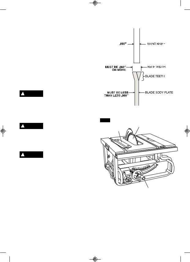
USINg THE CORRECT blAdE IMpORTANT: The saw blade provided on this tool has a carbide-tipped kerf width of .102” and a plate (body) thickness that is .071” thick. When looking for a replacement blade, select one with dimensions close to the original blade. This information may not be printed on the blades packaging. If not, check the manufacturers catalog or website. Bosch offers an extensive line of Premium-Quality Professional Saw Blades that match the requirements for this tool. You must select a blade with a kerf width of .092” or more and a plate (body) thickness .088” or less (Fig. 10).
! WARNING |
To reduce the risk of injury, do |
|
|
|
not use extra thin kerf saw |
|
|
blades. The kerf of the blade must be wider than |
|
||
.092”. Extra thin kerf saw blades (less than .092”) |
|
||
may cause the work piece to bind against the riving |
|
||
knife during cutting. It is recommended that the kerf |
|
||
of the replacement blade used on this saw be .092” |
|
||
or more. |
|
FIG. 11 |
|
|
|
||
! WARNING |
To reduce the risk of injury, do |
2 |
|
not use saw blades made with a |
1 |
||
thick body plate. If the replacement saw blade's |
|||
|
|||
plate thickness is greater than .088”, the riving knife |
|
||
would not properly serve as an aid to reduce kick- |
|
||
back. The replacement blade's plate thickness must |
|
||
be less than .088”. |
|
||
! WARNING |
To reduce the risk of injury, do |
|
|
|
not use blade “dampeners,” |
|
|
“stabilizers,” or “stiffening collars” on both |
|
||
sides of a replacement blade. These are metal |
|
||
plates positioned against the sides of the blade to |
|
||
reduce deflection that may occur when using thin |
|
||
saw blades. Use of these devices on both sides will |
|
||
prevent the blade from being properly aligned with |
|
||
the riving knife, which may bind the work piece dur- |
|
||
ing cutting. One “stabilizer” plate may be placed only |
3 |
||
against the outside of a thin replacement blade. |
|||
|
|||
These plates are not required with the supplied |
|
||
Bosch blade. |
|
|
|
-14-
 BM 2610014415 01-11 E:BM 2610012089 12-10 E 1/10/11 7:17 AM Page 15
CHANgINg THE blAdE
NOTE: Clean blade of any excess oil before installation.
1.Remove the table insert 1 (Fig. 11).
2.Raise the blade 2 to the maximum height by turning the control wheel 3 counterclockwise (Fig. 11).
3.Remove the arbor nut 4 and flange 5 (Fig. 12).
4.To loosen the arbor nut 4, use the open-end wrench 7 and align the wrench jaws on the flats of the flange to keep the arbor from turning. Place the box-end wrench 8 on the arbor nut 4 and turn counter-clockwise (to the front of the saw table) (Fig. 13).
5.Clean any sawdust from both blade collars before installing the blade. Install a 10" (25.4 cm) blade. Install the saw blade onto the arbor with the blade teeth pointing toward the front of the saw.
To avoid injury, do not use a blade larger or smaller than 10" diameter and 5/8" arbor.
6.Install the flange 5 against the blade 2 and thread the arbor nut 4 as far as possible by hand. Ensure that the blade is flush against the inner blade flange 6 (Fig. 12).
7.To tighten the arbor nut 4, use the open-end wrench 7 and align the wrench jaws on the flats of the flange to keep the arbor from turning. Place the box-end wrench 8 on the arbor nut 4 and turn clockwise (to the rear of the saw table) (Fig. 13).
8.Install the table insert 1 in the table recess. (Figure 11).
To avoid injury from a thrown workpiece, blade part, or blade contact, never operate the saw without the proper insert in place. Use the table insert when sawing. Use the dado insert when using a dado blade.
USINg CARbIdE-TIppEd blAdES
Handle carbide-tipped blades carefully. Carbide is very brittle and can be easily damaged. Use caution when you install, use or store the blades. Do not use a carbide-tipped blade that is bent or has bent teeth, or if the blade has cracks, is broken, or has missing/loose carbide tips. Do not operate a carbidetipped blade faster than its recommended speed.
Read, understand and follow all warnings and instructions provided with your carbide-tipped blades.
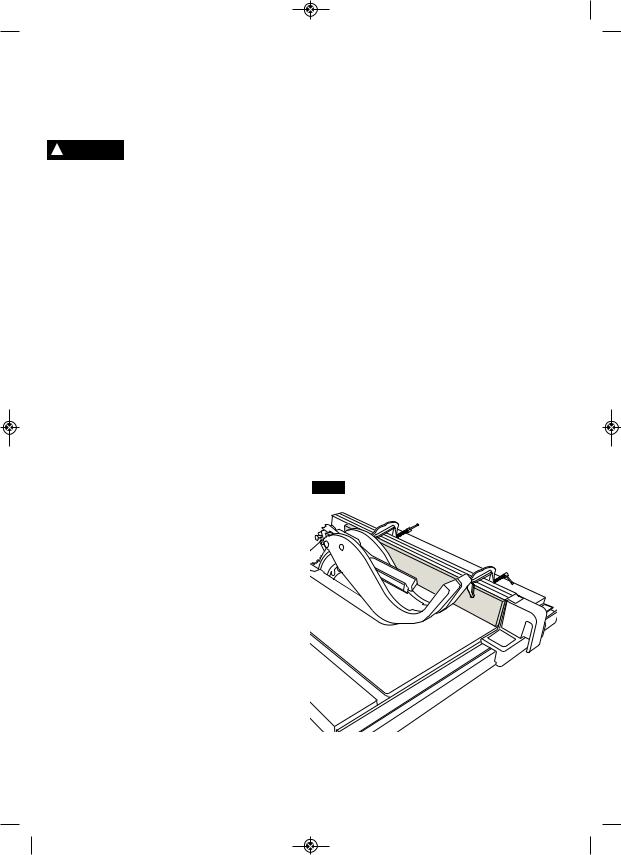
ATTACHINg RIp fENCE fOR USE
FIG. 12
 2
2
 5
5
 4
4
6
ANd STORAgE
1.Raise rip fence handle 1, so holding clamp 2 is out far enough to fit on the table 3 and into “V”
FIG. 13
7
 8
8
 4
4
groove located on the back of rear rail (Fig. 14).
2.Position the rip fence 4 over table 3 holding up the front end, first engage holding clamp 2 with rear rail.
3.Lower front end onto front rail 5.
4.Lower rip fence handle to lock.
Note: To store rip fence follow same procedure as above under the table (Fig. 15).
-15-

 BM 2610014415 01-11 E:BM 2610012089 12-10 E 1/10/11 7:17 AM Page 16
MOUNTINg THE TAblE SAW
If table saw is to be used in a permanent location, it should be fastened securely to a firm supporting surface such as a stand or workbench, using the four mounting holes 6 (Fig. 16).
1.If mounting to a workbench, the base should be bolted securely using 1/4" hex bolts (not included) through mounting holes 6.
Hint: If workbench is 3/4” thick, bolts will have to be at least 3-1/2” long - if workbench is 1-1/2” thick, bolts should be at least 4-1/2” long.
2.Locate and mark where the saw is to be mounted, relative to holes in the base of the tool.
3.Drill four (4) 3/8" diameter holes through workbench.
4.Place table saw on workbench aligning holes in base with holes drilled in workbench.
5.Insert four (4) 1/4" dia. bolts through holes in base and supporting surface; then secure with (4) 1/4” flat washers and (4) 1/4" hex nuts.
FIG. 14 |
|
4 |
|
|
1 |
2 |
2 |
1 |
|
|
3 3
5
FIG. 15 |
RIP FENCE |
|
|
|
STORAGE |
FIG. 16
6
1/4” HEX BOLT,
WASHER &
HEX NUT
X4
-16-

 BM 2610014415 01-11 E:BM 2610012089 12-10 E 1/10/11 7:17 AM Page 17
Adjustments
AdjUSTINg 0 ANd 45 dEgREE
pOSITIVE STOpS
Your saw is equipped with positive stops for fast and accurate positioning of the saw blade at 90 and 45 degrees to the table.
To prevent personal injury, always disconnect plug from
power source when making adjustments.
1.Turn elevation wheel 2 clockwise and raise blade to maximum height (Fig. 17).
AdjUSTINg 0 dEgREE pOSITIVE STOp:
2.Loosen the blade tilt lock handle 1 and push the elevation wheel 2 to the left as far as possible and tighten the blade tilt lock handle 1 (Fig. 17).
3.Place a combination square on the table with one end of square against the blade as shown (Fig. 18), and check to see if the blade is 90 degrees to the table. If the blade is not 90 degrees to the table, loosen the blade tilt lock handle 1, loosen 90 degree adjustment screw 4, loosen 90 degree bevel stop cam 5 and push the elevation wheel until the blade is 90 degrees to the table.
4.Tighten blade tilt lock handle 1, rotate the bevel stop cam 5 until it touches the bevel stop housing 7, then tighten 90 degree adjustment screw 4.
5.Loosen adjustment screw 6 and adjust pointer 3 to indicate 0 degrees on the bevel scale.
AdjUSTINg 45 dEgREE pOSITIVE STOp:
6.Loosen the blade tilt lock handle 1 and push the elevation wheel 2 to the right as far as possible and tighten the blade tilt lock handle 1.
7.Place a combination square on the table with one end of square against the blade as shown (Fig. 19), and check to see if the blade is 45 degrees to the table. If the blade is not 45 degrees to the table, loosen the blade tilt lock handle 1, loosen 45 degree adjustment screw 8, loosen 45 degree bevel stop cam 9 and push the elevation wheel until the blade is 45 degrees to the table.
8.Tighten blade tilt lock handle 1, rotate the 45 degree bevel stop cam 9 until it touches the bevel stop housing 7, then tighten 45 degree adjustment screw 8.
Note: Your GTS1031 is able to achieve a bevel up to 47 degrees left and -2 degrees right. To reach these points, follow the procedure above and reset stops as needed.
FIG. 17
|
3 |
|
7 |
8 |
|
9 |
||
|
||
6 |
|
5 |
|
|
1 |
2 |
|
4 |
|||||
|
|||||
FIG. 18
FIG. 19
-17-
 BM 2610014415 01-11 E:BM 2610012089 12-10 E 1/10/11
AdjUSTINg blAdE pARAllEl TO THE MITER gAUgE SlOTS
The blade was adjusted parallel to the miter gauge slots at the factory. In order to insure accurate cuts and help prevent kickback, this adjustment should be rechecked. If adjustment is necessary, follow the steps below.
To prevent personal injury, al- ! WARNING ways disconnect the plug from
power source before making any adjustments.
1.Turn elevation wheel and raise blade as high as it will go.
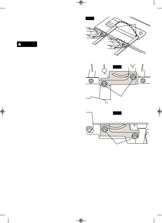
2.Select a point on the body of the saw blade that is set to the left when viewing blade from the front of saw, and mark 1 with a pencil (Fig. 20).
3.Place the base of a combination square against the edge of the miter gauge slot, and extend the sliding rule of square so it just touches the marked point 1 on the body of the saw blade at the rear of the table.
4.Rotate blade and check the same marked point 1 of the saw blade at the front of the table (Fig. 20).
5.If the front and back measurements, shown in Figure 20, are not identical, loosen the four alignment bolts 2, located on the underside of the table at the front and rear of the saw with hex wrench supplied with your saw (Fig. 21 & 22). Carefully move the saw blade until the blade is parallel to the miter gauge slot, and securely tighten all four bolts.
7:17 AM Page 18
FIG. 20
1
FIG. 21
|
UNDER FRONT |
2 |
OF TABLE |
|
FIG. 22
UNDER REAR OF TABLE
2
-18-
 BM 2610014415 01-11 E:BM 2610012089 12-10 E 1/10/11 7:17 AM Page 19
AlIgNINg RIp fENCE
! WARNING To prevent personal injury, always disconnect plug from power source
before making any adjustments. The rip fence must be parallel with the SAWBLADE in order to prevent KICKBACK when ripping.
Your table saw is equipped with a Self-Aligning, Squarelock™ rip fence. Once the adjustments below have been made, the rip fence will self align when the fence is locked into position.
NOTE: The blade must be parallel with the miter gauge slots (see page 18) and be perpendicular to table before proceeding with rip fence alignment.
To prevent personal injury, always make sure the rip fence is locked
before making rip cuts.
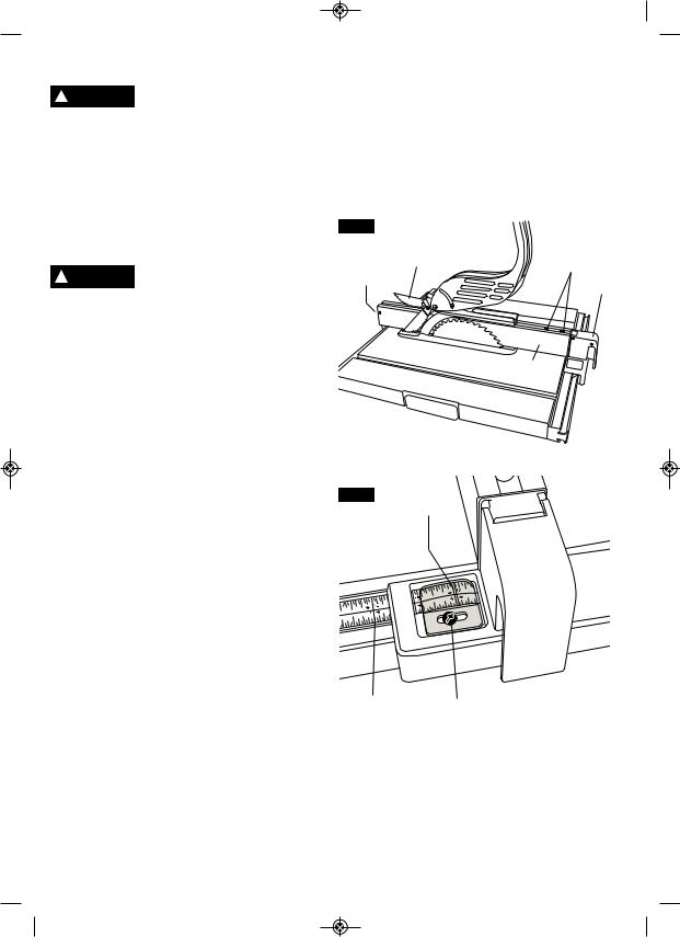
1.Lift both guard barriers 2 to their up locked position.
2.Raise lock handle 1 and slide fence 3 until it is alongside the sawblade, by lifting right side pawl 4 above fence (Fig. 23).
The fence should touch the blade teeth at the front and rear of the blade. If fence does not touch the teeth at front and rear of blade continue with the following the steps:
3.Loosen the two screws 5 on the top front section of the rip fence using the included 5mm hex wrench.
4.Move fence 3 until it touches the teeth and is parallel to the blade.
5.Hold fence in place and lower lock handle, check to make sure the fence stayed parallel to the blade then tighten screws (Fig. 23).
6.Clamp rip fence to check if it holds securely at front and rear. If rear is not clamped securely, unclamp fence and turn rear clamp adjustment screw 6 clockwise for increased clamping. Try clamping the fence to verify if it self aligns and clamps tightly at the front and rear. Overtightening of the rear clamp adjustment screw 6 will cause the rip fence to be non-self aligning (Fig. 23). Overtightening may cause friction or “chatter” when fence is moved side to side.
RIp fENCE pOINTER AdjUSTMENT
The distance of the rip fence body from the blade when ripping on the right side of the blade is determined by lining the pointer 7 with the desired dimension on the scale 8 (Fig. 24).
TO SET THE RIp fENCE pOINTER:
1.Lift both guard barriers 2 to their up locked position (Fig. 23).
2.Raise lock handle 1 and slide fence 3 until it is alongside the sawblade, by lifting right side pawl 4 above fence. Lock fence in place (Fig. 23).
3.Loosen pointer adjustment screw 9, adjust pointer 7 to “0” mark on lower scale 8, then re-tighten screw 9 (Fig. 24).
FIG. 23
 2
2
4 5
6 |
1 |
|
3
FIG. 24
7
8 9
-19-
 BM 2610014415 01-11 E:BM 2610012089 12-10 E 1/10/11
TAblE pOINTER AdjUSTMENT
If an adjustment to the table pointer is necessary, loosen pointer adjustment screw 1, adjust pointer 2 and tighten screw 1 (Fig. 25).
The table pointer should always be adjusted relative to fence pointer.
1.Adjust fence pointer to (zero) - see “Rip Fence Pointer Adjustment”.
2.Make sure the table is in the closed position and slide fence to the right until the fence pointer is at 10”. (Note: A portion of the fence will be off the rail.)
3.Look at fence pointer and note 10” on lower scale.
4.Adjust the table pointer 2 to the same reading on upper scale as that shown on the fence pointer. Both pointers must agree when fence is at this position.
FIG. 25
1 2
RIVINg KNIfE AlIgNMENT
IMpORTANT: The Riving Knife 1 must always be in line with the Saw Blade 2. The Riving Knife 1 is thinner than the width of the Kerf 4 by approximately five thicknesses of paper 5 on each side, depending on the thickness of paper used (Fig 26). Note: The Kerf is the width of the cut made by the teeth on the saw blade.
! WARNING |
To prevent personal injury, always |
|
disconnect plug from power |
|
source before making any adjustments and when attaching or removing the Smart Guard System.
CHECKINg RIVINg KNIfE AlIgNMENT NOTE: The Riving Knife has been properly aligned at the factory - Check the alignment before making any adjustments.
1.Raise the Saw Blade to maximum height and set the bevel angle to 0°.
7:17 AM Page 20
2.Remove the Barrier Guard Assembly and AntiKickback Device (see manual).
3.Place the Rip Fence 3 on the right side and slide it until it touches the tips of the Saw Blade 2 - Lock fence.
4.Check the alignment:
A.From the top, look down over the Fence and check that the Riving Knife is in line (front to back) with the blade and parallel with the fence.
B.Slide the fence away from the blade. Look over the front of the blade and check that the Riving Knife is in line with the blade.
C.If steps A or B show misalignment, proceed to “Adjusting Riving Knife”.
FIG. 26
1 |
5 |
5 |
|
WORK |
5 |
|
|
|
|
|
|
|
4
2
LOOKING DOWN
ON SAW
AdjUSTINg RIVINg KNIfE
1.Raise the Saw Blade 2 to maximum height and set the bevel angle to 0°.
2.Remove the Barrier Guard Assembly and AntiKickback Device (see manual).
3.Remove the Table Insert.
4.Place the Rip Fence 3 on the right side and slide it until it touches the tips of the Saw Blade 2 - Lock fence.
5.Loosen Hex Nut 6 with 10mm open end wrench (Fig. 27). Slightly loosen Clamping Screws 8 (1/4- 1/2 turns) using a 5mm Allen wrench provided with table saw (stored in the rear of saw). Loosen Set Screw 7 using a flat screwdriver (Fig. 27).
6.Make four folds in a small piece of paper (6” x 6”) forming five layers (Fig. 26). Paper 5 is used as a “Spacing Gauge.”
-20-
 BM 2610014415 01-11 E:BM 2610012089 12-10 E 1/10/11 7:17 AM Page 21
NOTE: The spacing instructions are based on using the standard kerf blade supplied with your GTS1031. If a smaller or larger kerf blade is used, adjust the spacer. For instance, if the kerf of the replacement blade is larger, use 6 or more thicknesses of paper and if it is smaller, use 4 or less thicknesses. Depending on the type of paper used as a spacer, you may need to modify the number of folds for proper alignment.
7.Insert folded paper 5 between Riving Knife 1 and Fence 3.
D.Slowly turn the Set Screw 7 while watching the Riving Knife tilt until it is in line with the blade.
E.Recheck squareness of riving knife to table by sliding fence against blade. Readjust if necessary.
8.After completing adjustments:
A.Lightly tighten hex nut 6 (hold set screw position with screwdriver while tightening nut).
B.Fully tighten Clamp Screws 8 with Allen wrench. Then fully tighten the hex nut.
A. Hold Riving Knife and paper firmly against |
NOTE: Check that the riving knife stays in line with |
||
Fence (Fig. 27 & 28). |
blade when the blade is tilted at any angle. Replace |
||
FIG. 27 |
5 |
the Barrier Guard Assembly and Anti-Kickback De- |
|
vice before making cuts. |
|||
1 |
|||
|
|
||
|
|
AdjUSTINg THE TAblE INSERT |
|
8 |
|
The GTS1031 table insert slot includes four (4) ad- |
|
|
justment screws 9 to set the height (Fig. 29). Place |
||
|
7 |
the insert 10 onto the table 11. Place a straight edge |
|
6 |
(such as the metal ruler from a combination square) |
||
|
|||
|
across the table top and insert top – the surfaces |
||
8 |
|
||
3 |
should be at the same level. If adjustment is neces- |
||
|
sary, use the included 2 mm “L wrench” (packed with |
||
2 |
|
the table insert) to rotate each set screw up or down. |
|
|
|
||
|
|
FIG. 29 |
|
|
|
10 |
FIG. 28 |
5 |
|
|
|
|
3 |
11 |
9 |
|
8
B.Lightly tighten the clamp screws 8.
C.Remove the paper - Slide fence away from blade.
-21-
 BM 2610014415 01-11 E:BM 2610012089 12-10 E 1/10/11 7:17 AM Page 22
basic Table Saw Operation
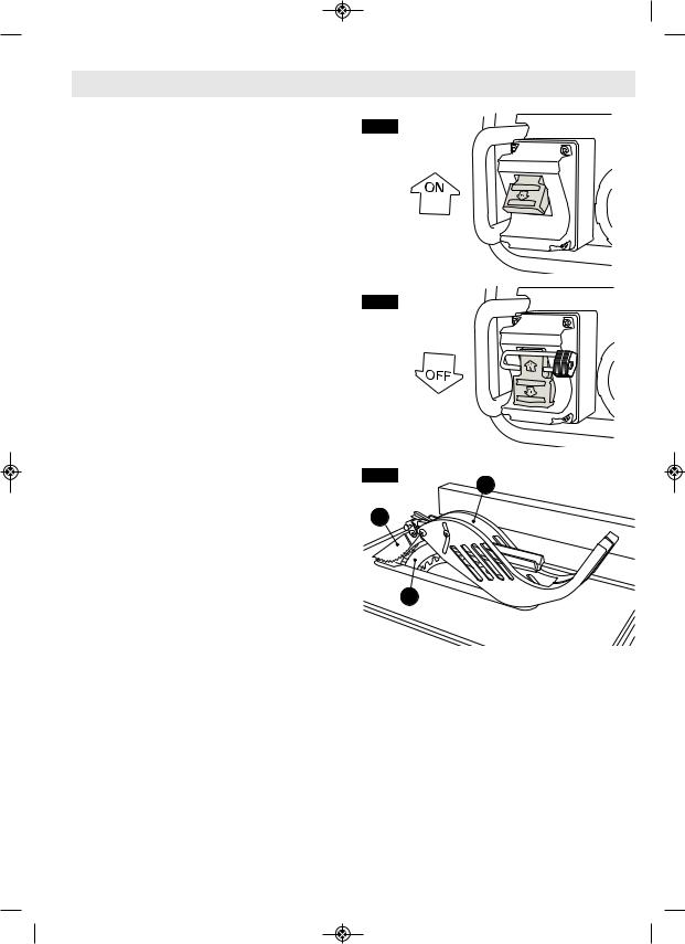
SAfETy pOWER SWITCH
NOTE: This table saw has a safety feature that helps prevent accidental starting.
To turn saw on: lift switch lever by pinching side walls and pulling up. This action starts the saw (Fig. 30)
To turn off power: push switch lever down to its original position (Fig. 31).
To prevent unauthorized use, the switch can accommodate a padlock with a long, 3/16" or 1/4” diameter shackle (not provided with table saw), (Fig. 31).
SMART gUARd SySTEM
The Bosch Smart Guard has been designed for modularity, enabling the use of multiple combinations of the three main components – Main barrier guards, Anti-kickback device, and riving knife. Additionally, the riving knife can be quickly adjusted to three positions (high, middle, and stored), depending on the application requirement.
COMpONENT pARTS (fIgURE 32):Riving Knife
The Riving Knife is the central element of the Bosch Smart Guard blade guarding system, serving as the attachment point for both the Main Barrier Guard and the Anti-Kickback Device. In the event that the Main Barrier Guard and AntiKickback Device are removed, the Riving Knife maintains its functionality as material splitter, and is adjustable to three positions. Because of this adjustability, the Riving Knife can be appropriately positioned for all cutting applications.
Main barrier guard
The main guard is comprised of a pair of plastic barriers attached to the metal upper barrier guard. The side barriers (one to the left and one to the right of the blade) operate independently of one another, maintaining maximum blade coverage during cutting operations. The main guard incorporates a quick-connect attachment point and can be attached or removed from the blade guarding system independent of the Anti-Kick- back Device and Riving Knife.
Note: To best secure the main guard for relocation, adjust the blade to its lowest position. This keeps the guard tight to the table surface and prevents damage related to the guard swinging during relocation. If transporting over a longer distance on/off the job, place guard in it’s below table storage position. (See figure 33, on page 23).
FIG. 30
FIG. 31
FIG. 32
2
3
1

Anti-Kickback device
In the event of kickback, the Anti-Kickback Device, (also known as dogs, or pawls) is intended to help prevent the board from being thrown in the direction of the user. The sharp teeth of the pawls are intended to “catch” the material in the event of kickback.
ATTACHMENT/REMOVAl
(see pages 12 & 13 for detailed instructions) The three primary components of the Smart Guard blade guarding system are designed for rapid attachment, adjustment, and/or removal without the need for additional tools.
-22-
 BM 2610014415 01-11 E:BM 2610012089 12-10 E 1/10/11 7:17 AM Page 23
The Main Barrier Guard component can be quickly |
FIG. 33 |
|
|
attached and detached through the use of a quick |
|
|
|
release lever. The guard is attached by seating the |
|
|
|
crossbar into the top of the Riving Knife and engag- |
|
|
|
ing the locking lever. Following this process in re- |
|
|
|
verse, the guard can be easily removed for special |
|
|
|
operations such as dados or rabbets. |
3 |
|
|
The Anti-Kickback Device can be easily attached by |
|
||
|
|
||
aligning the attachment pin with the hole in the rear |
|
|
|
of the riving knife. It can be easily removed by de- |
|
|
|
pressing the compression pads on either side of the |
|
|
|
Anti-Kickback Device and lifting it away. |
|
1 |
|
The Riving Knife can be easily adjusted to one of |
2 |
||
|
|||
three heights by removing the table insert, raising |
|
|
|
the blade to its full height and releasing the riving |
|
|
|
knife release lever at the base of the Riving Knife. |
|
|
|
The Riving Knife should be locked in its highest po- |
|
|
|
sition for use with the Main Barrier Guard and Anti- |
|
|
|
Kickback Device. It can be adjusted to its middle |
|
FIG. 34 |
|
position for non-through cuts and for use as a mate- |
|
||
|
|
||
rial splitter without the Main Barrier Guard and Anti- |
|
|
|
Kickback Device. |
|
|
In the event that the Riving Knife can not be used for a specific cut, it can be adjusted to its lowest position, thus placing it 1” above the surface of the table (while the blade is at its full height).
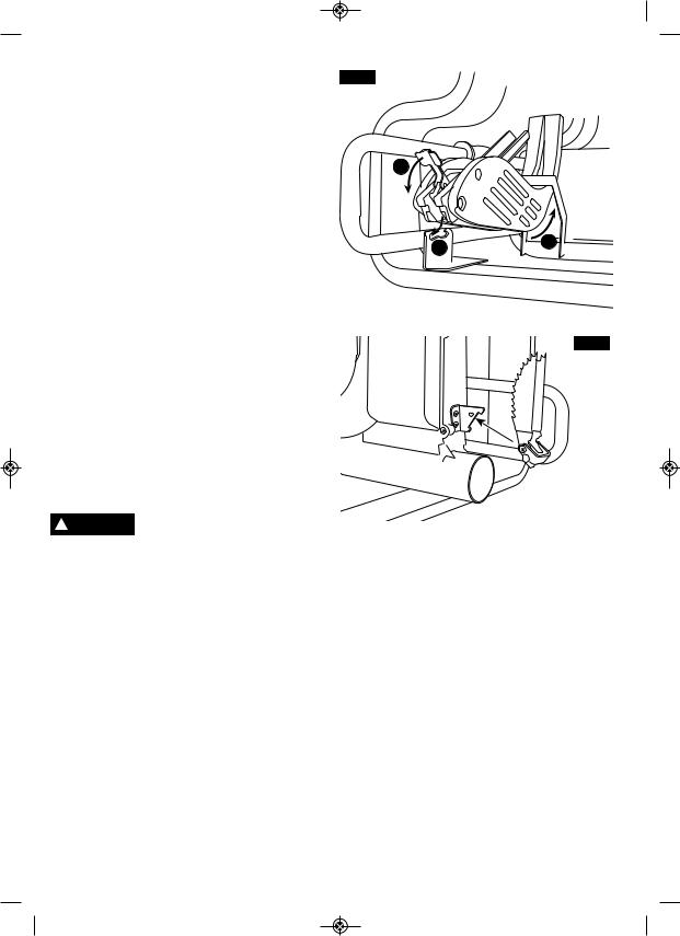
SySTEM STORAgE
When not in use, the Main Barrier Guard and AntiKickback Device can be stored under the right side table extension.
Use of all the components of the ! WARNING Smart Guard System, including
Main Barrier Guard, Anti-Kickback Device, and Riving Knife is highly recommended to provide protection against accidents and injury.
1.Slide the front of the Main Barrier Guard assembly up and into the U-bracket at the front right side of the saw (Fig. 33).
2.Pivot the rear of the guard down and onto the mounting bracket.
3.Lock the Main Barrier Guard assembly into place in the same manner as you would attach it to the Riving Knife.
4.Locate the Anti-Kickback Device storage location just above the Dust Chute on the back of the tool. Attach the Anti-Kickback Device to the hanging bracket in the same manner that it attaches to the Riving Knife (Fig. 34).
-23-

 BM 2610014415 01-11 E:BM 2610012089 12-10 E 1/10/11 7:17 AM Page 24
|
|
blAdE bEVEl CONTROl |
|
EXTENdINg TAblE EXTENSION |
|
Loosen blade bevel lock handle 1 counterclockwise |
To extend the table, raise the table extension lock |
||||
(Fig. 35), slide the elevation wheel 2 until pointer 3 |
handle 4 (Fig. 35) and slide table extension 5 to de- |
||||
is at desired angle and tighten blade tilt lock handle |
sired width (Fig 35a). To secure table setting, lower |
||||
1 clockwise. |
the lock handle 4. |
||||
|
|
|
|
|
|
|
FIG. 35 |
FIG. 35a |
|||


 4 3 1 2
5 |
USINg THE RIp fENCE pOINTER |
the locking lever, will hang off the rail. The maximum |
|
WHEN TAblE IS NOT EXTENdEd |
cutting capacity to the right of the blade when the |
|
The rip fence pointer shows the distance from the |
extension table is fully extended is 18”. To achieve |
|
blade to rip fence through a convenient viewing. |
this capacity, a portion of the fence glide pads, lo- |
|
Align rip fence pointer 4 with lower portion of scale |
cated underneath the locking lever, will hang off the |
|
rail. In either case the rip fence pointer should never |
||
5. The lower scale can be used for widths up to 10 |
||
be positioned beyond 10” on the lower scale for |
||
inches (Fig. 36). |
||
maximum cutting capacity (Fig. 37). |
||
|
USINg THE TAblE pOINTER |
|
|
WHEN TAblE IS EXTENdEd |
FIG. 37 |
|
The upper portion of scale 6 is used for rip cut 10 to |
BODY OF FENCE |
|
18 inches. Align table pointer 7 with upper portion of |
|
|
scale 6 (Fig. 36). |
|
|
NOTE: The maximum cutting capacity to the right of |
|
|
the blade when the extension table is closed is 10”, |
|
|
as noted on the scale. To achieve this capacity, a |
EDGE OF TABLE |
|
portion of the fence glide pads, located underneath |
||
|
FIG. 36 |
7 |
|
11 |
|
4 |
||
|
|
||
|
|
|
6
5
-24-

 BM 2610014415 01-11 E:BM 2610012089 12-10 E 1/10/11 7:17 AM Page 25
WORK HElpERS
Before cutting any wood on your saw, study all of the “Basic Saw Operations”.
Notice that in order to make some of the cuts, it is necessary to use certain devices, “Work Helpers”, like the Push Stick, the Push Block and the Auxiliary Fence, which you can make yourself.
After you have made a few practice cuts, make these “helpers” before starting any projects. Make the “Push Stick” first. (A push stick is included standard with the GTS1031).
pUSH STICK ANd pUSH blOCK
Make the Push Stick 1 using a piece of 1 x 2 as shown (Fig. 38).
Make the Push Block 2 using pieces of 3/8” plywood 3 and 3/4" hardwood 4 (Fig. 39). For proper use of push block (see page 30).
The small piece of wood, 3/8” x 3/8” x 2-1/2”, should be GLUED to the plywood… DO NOT USE NAILS. This is to prevent dulling the sawblade in the event you mistakenly cut into the Push Block.
Position the handle in the center of the plywood and fasten together with glue and woodscrews.
Use a push stick whenever the fence is 2 inches or more from the blade. Use a push block when the operation is too narrow to allow the use of a push stick. For proper use, see page 30.
Both a push stick or block should be used in the place of the user’s hand to guide the material only between the fence and blade.
When using a push stick or push block, the trailing end of the board must be square. A push stick or block against an uneven end could slip off or push the work away from the fence.
AUXIlIARy fENCE
Make one using pieces of 3/8" plywood 3 and 3/4" hardwood 4. Fasten together with glue and woodscrews (Fig. 40).
NOTE: Since the Push Block 2 is used with the Auxiliary Fence 5, the 4-3/4" dimensions must be held identical on both the pieces.
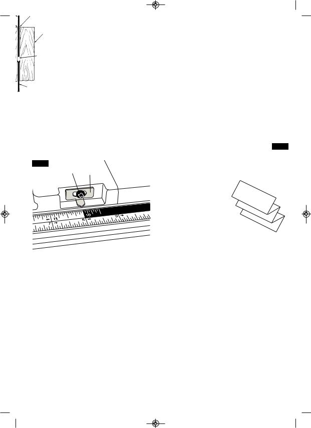
MAKINg A fEATHERbOARd
Figure 41 illustrates dimensions for making a typical featherboard. It should be made from a straight piece of wood that is free of knots or cracks.
Kerf 5 should be about 1/4" apart (fig. 41).
FIG. 38 |
WORKPIECE |
3/4 |
|
|
|
|
END |
|
1 |
|
|
|
|
|
|
|
|
|
45° |
1-1/2 |
|
|
|
NOTCH |
|
1/4 |
1/4 |
15 |
|
|
|
|
||
|
1/4 |
|
|
|
FIG. 39 |
|
|
|
4 |
|
|
|
12 |
|
|
4-3/4 |
|
|
|
|
|
5 |
|
|
|
|
|
|
|
|
3/8 |
12 |
|
2 |
2-1/2 |
|
|
2-1/2 |
|
|
|
|
|
|
|
5-1/8 |
|
|
|
|
|
|
3/8 |
3/8 |
THESE |
|
|
3 |
|
|
|
|
||
EDGES |
|
|
|
|
MUST BE PARALLEL |
|
|
||
FIG. 40 |
|
|
|
|
|
3 |
|
|
|
|
|
|
4 |
|
5 |
|
|
|
2-1/4 |
|
|
|
|
|
THIS FACE AND |
|
4-3/4 |
|
|
21-1/2 |
|
|
||
THIS EDGE |
|
|
||
|
|
|
||
MUST BE |
|
|
5-1/2 |
|
PARALLEL |
|
|
||
|
|
|
||
FIG. 41 |
|
|
|
8 |
|
|
|
|
|
|
|
25 |
|
5 |
|
|
|
|
|
5
4-1/2
3/4
NOTE: All dimensions in inches.
-25-
 BM 2610014415 01-11 E:BM 2610012089 12-10 E 1/10/11
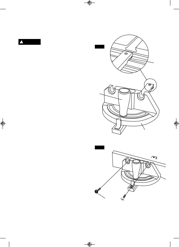
USINg THE MITER gAUgE
CROSSCUTTING, MITER CUTTING, BEVEL CUTTING, COMPOUND MITER CUTTING and when RABBETING across the end of a narrow workpiece, the MITER GAUGE is used.
! WARNING For your own safety, always observe the following safety precau-
tions in addition to the safety instructions on Pages 2, 3, 4 & 5.
Never make these cuts freehand (without using the miter gauge or other auxiliary devices) because the blade could bind in the cut and cause a KICKBACK or cause your fingers or hand to slip into the blade.
Always lock the miter gauge securely when in use.
Remove rip fence from table during any operations which utilize the miter gauge.
The miter includes a “T” groove disk 1 for easy insertion into table groove and quicker removal from the table (Fig 42).
When cross cutting and the blade set at 90º or 45º to the table, the miter gauge can be used in either slot on the table. When cross cutting and the blade is tilted, use slot on right side of table where the blade is tilted away from your hands and miter gauge.
To adjust the miter angle:
Loosen lock knob 2 and set the miter gauge body 3 so the pointer 4 is at desired angle, then tighten lock knob 2 (Fig. 42).
MITER gAUgE AUXIlIARy fACINg
The GTS1031 miter gauge is designed to accept an Auxiliary Facing with pre-molded holes for fastening a suitable piece of smooth straight wood. Utilize the miter gauge as a template to attach with proper fasteners (Fig. 43).
Example:
A.Drill 5/32" dia. holes thru (board 3/4" thick, 3" high, and desired length).
B.Attach with two No. 12 round head wood screws 1-1/2" long, 6, not included (Fig. 43).
Be sure screws never protrude above outside surface of facing.
Be sure facing does not interfere with the proper operation of the saw blade guard.
7:17 AM Page 26
NOTE: When bevel crosscutting, attach facing so that it extends to the right of the miter gauge and use the miter gauge in the groove to the right of the blade.
FIG. 42
1
2
4
3
FIG. 43
5 
6 

-26-
 BM 2610014415 01-11 E:BM 2610012089 12-10 E 1/10/11 7:17 AM Page 27
CROSSCUTTINg
CROSSCUTTING is known as cutting wood across the grain, at 90°, or square with both the edge and the flat side of the wood. This is done with the miter gauge set at 90° (Fig. 44).
Make sure blade guard is installed for all “thru-saw- ing” operations (when sawblade cuts entirely thru the thickness of the workpiece). Replace guard IMMEDIATELY after completion of dadoing or rabbeting cuts.
manufacturing. For maximum accuracy when using the miter gauge, always “favor” one side of the groove in the table. In other words, don’t move the miter gauge from side to side while cutting but keep one side of the bar riding against one side of the groove.
TIp: Glue a piece of sandpaper to the face of the miter gauge head. This will help prevent the workpiece from “creeping” while it is being cut.
Have blade extend approximately 1/8" above top of workpiece. Additional blade exposure would increase the hazard potential.
Do not stand directly in front of the blade in case of a THROWBACK (small cut-off piece caught by the back of the blade and thrown toward the operator). Stand to either side of the blade.
Keep your hands clear of the blade and out of the path of the blade.
If blade stalls or stops while cutting, TURN SWITCH OFF before attempting to free the blade.
Do not reach over or behind the blade to pull the workpiece through the cut … to support long or heavy workpieces … to remove cut-off pieces of material or FOR ANY OTHER REASON.
Do not pick up small pieces of cut-off material from the table. REMOVE them by pushing them OFF the table with a long stick. Otherwise they could be thrown back at you by the rear of the blade.
Do not remove small pieces of cut-off material that are close to or may become TRAPPED inside the blade guard while the saw is RUNNING. THIS COULD ENDANGER YOUR HANDS or cause a KICKBACK. Turn the saw OFF. After the blade has stopped turning, lift the guard and remove the piece.
If workpiece is warped, place the CONCAVE side DOWN. This will help prevent it from rocking while it is being cut.
The graduations on the miter gauge provide accuracy for average woodworking. In some cases where extreme accuracy is required, when making angle cuts, for example, make a trial cut and then recheck it with an accurate square or protractor.
If necessary, the miter gauge head can be swiveled slightly to compensate for any inaccuracy.
TIp: The space between the miter gauge bar and the groove in the table is held to a minimum during
The miter gauge may be used in either of the grooves in the table. Make sure it is locked.
When using the miter gauge in the LEFT hand groove, hold the workpiece firmly against gauge head with your left hand, and grip the lock knob with your right hand.
When using the RIGHT hand groove, hold the workpiece with your right hand and the lock knob with your left hand.
FIG. 44
-27-

 BM 2610014415 01-11 E:BM 2610012089 12-10 E 1/10/11
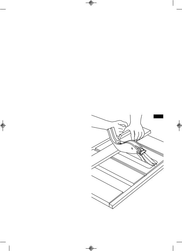
REpETITIVE CUTTINg
REPETITIVE CUTTING is known as cutting a quantity of pieces the same length without having to mark each piece (Fig. 45).
When making repetitive cuts from a long workpiece, make sure it is supported.
! WARNING |
Never use the rip fence as a length |
|
stop because the cutoff piece could |
|
bind between the fence and the blade causing a kickback.
7:17 AM Page 28
When using the RIGHT hand groove, hold the workpiece with your right hand and the lock knob with your left hand.
FIG. 46
1.When making repetitive cuts, clamp a block of wood 3" long to the table at desired length to act as a length stop.
When clamping the block, make sure that the end of the block is well in
front of the sawblade. Be sure it is clamped securely.
2.Slide the workpiece along the miter gauge until it touches the block … hold it securely.
3.Make the cut … pull the workpiece back … push the cut-off piece off the table with a long Push Stick … DO NOT ATTEMPT TO PICK IT UP AS THIS COULD ENDANGER YOUR HANDS.
bEVEl CROSSCUTTINg
BEVEL CROSSCUTTING is the same as crosscutting except that the wood is also cut at a bevel angle (Fig. 47) … other than 90° with the flat side of the wood.
FIG. 45
MITER CUTTINg
MITER CUTTING is known as cutting wood at an angle other than 90° with the edge of the wood. Follow the same procedure as you would for crosscutting (Fig. 46).
Adjust the miter gauge to the desired angle, and lock it.
The miter gauge may be used in either of the grooves in the table.
When using the miter gauge in the LEFT hand groove, hold the workpiece firmly against the miter gauge head with your left hand, and grip the lock knob with your right hand.
Adjust the blade to the desired angle.
Use the Miter Gauge in the groove to the RIGHT or the LEFT of the blade.
COMpOUNd MITER CUTTINg
COMPOUND MITER CUTTING is a combination of miter cutting and bevel crosscutting. The cut is made at an angle other than 90° to both the edge and the flat side of the wood (Fig. 47).
Adjust the miter gauge and the blade to the desired angle and make sure miter gauge is locked.
FIG. 47
-28-
 BM 2610014415 01-11 E:BM 2610012089 12-10 E 1/10/11 7:17 AM Page 29
USINg THE RIp fENCE
RIPPING, BEVEL RIPPING, RESAWING AND RABBETING are performed using the RIP FENCE together with the AUXILIARY FENCE / WORK SUPPORT, PUSH STICK OR PUSH BLOCK.
! WARNING For your own safety, always observe the following safety precau-
tions in addition to the safety instructions on Pages 2, 3, 4 & 5.
1.Never make these cuts FREEHAND (without using the rip fence or auxiliary devices when required) because the blade could bind in the cut and cause a KICKBACK.
2.Always lock the rip fence securely when in use.
3.Remove miter gauge from table during any operations which utilize the rip fence.
4.Make sure blade guard is installed for all thrusawing type cuts. Replace the guard IMMEDIATELY following completion of resawing, rabbeting, or dadoing operations.
Frequently check the action of the ANTIKICKBACK PAWLS by passing the workpiece alongside of the spreader while saw is OFF.
Pull the workpiece TOWARD you. If the PAWLS do not DIG into the workpiece and HOLD it … the pawls must be REPLACED or SHARPENED. (See “Maintenance” on Page 34 & 35).
5.Have blade extend approximately 1/8" above top of workpiece. Additional blade exposure would increase the hazard potential.
6.Do not stand directly in front of the blade in case of a KICKBACK. Stand to either side of the blade.
7.Keep your hands clear of the blade and out of the path of the blade.
8.If the blade stalls or stops while cutting, TURN SWITCH OFF before attempting to free the blade.
9.Do not reach over or behind the blade to pull the workpiece through the cut … to support long or heavy workpieces … to remove small cut-off pieces of material or FOR ANY OTHER REASON.
10.Do not pick up small pieces of cut-off material from the table. REMOVE them by pushing them OFF the table with a long stick. Otherwise they could be thrown back at you by the rear of the blade.
11.Do not remove small pieces of cut-off material that may become TRAPPED inside the blade guard while the saw is RUNNING. THIS COULD ENDANGER YOUR HANDS or cause a KICKBACK. Turn the saw OFF and disconnect power source. After the blade has stopped turning, lift the guard and remove the piece.
12.If workpiece is warped, place the CONCAVE side DOWN. This will prevent it from rocking while it is being ripped.
RIp fENCE AUXIlIARy fACINg
When using dado accessories, an auxiliary facing board should be used. This will help prevent damage to the aluminum fence. The facing should be made of 3/4 inch thick wood (Fig. 48).
parts Required:
3/4” thick wood board (solid or plywood) cut to size.
Two (2) clamps.
The facing is made to the same height (2-3/4”) as the fence and can work with the blade guard system in place when moving the fence to contact the blade. Use two clamps to clamp the 3/4 inch thick wood board to the rip fence.
NOTE: The auxiliary facing board, should also be used when cutting material less than 3/16” thick.
FIG. 48
-29-
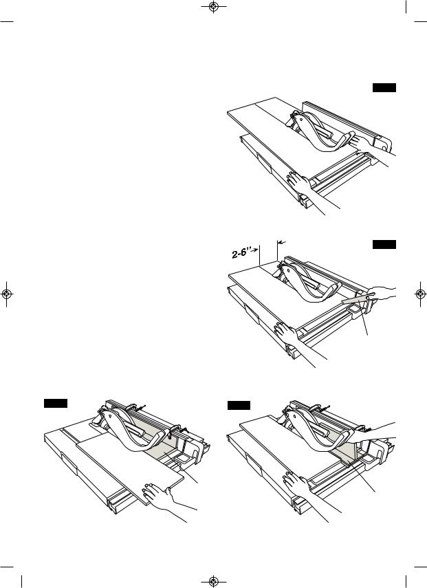
 BM 2610014415 01-11 E:BM 2610012089 12-10 E 1/10/11
RIppINg
RIPPING is known as cutting a piece of wood with the grain, or lengthwise. This is done using the rip fence. Position the fence to the desired WIDTH OF RIP and lock in place. Before starting to rip, be sure:
A.Rip Fence is parallel to sawblade.
B.Riving knife is properly aligned with sawblade.
C.Antikickback pawls are functioning properly.
When ripping LONG BOARDS or LARGE PANELS, always use an auxiliary work support (Fig. 49).
When ripping a workpiece that is less than 3/16 inch thick, always use auxiliary fence described in rip fence auxiliary facing section (page 29).
bEVEl RIppINg
When bevel ripping material 6" or narrower, use fence on the right side of the blade ONLY. This will provide more space between the fence and the sawblade for use of a Push Stick. If the fence is mounted to the left, the sawblade guard may interfere with proper use of a Push Stick.
When “WIDTH OF RIP” is 6" and WIDER use your RIGHT hand to feed the workpiece, use LEFT hand ONLY to guide the workpiece … do not FEED the workpiece with the left hand (Fig. 49).
When “WIDTH OF RIP” is 2" to 6" wide USE THE PUSH STICK 1 to feed the work (Fig. 50).
When WIDTH OF RIP is NARROWER than 2" the Push Stick CANNOT be used because the guard will interfere … USE the AUXILIARY FENCE, and PUSH BLOCK.
Attach auxiliary fence 2 to rip fence with two “C” clamps (Fig. 51).
Feed the workpiece by hand until the end is approx. 1" from the front edge of the table. Continue to feed
7:17 AM Page 30
using the PUSH BLOCK 3 on top of auxiliary fence UNTIL THE CUT IS COMPLETE (Fig. 52).
FIG. 49
FIG. 50
1
FIG. 51 |
FIG. 52 |
|
2
3
-30-
 Loading...