


 Loading...
City Tie Plug-in Module
FPE-1000-CITY
|
|
|
|
|
|
|
|
|
|
|
|
|
|
|
en |
Installation Guide |
pt |
Manual de Instalação |
|
es |
Guía de instalación |
th |
|
|

FPE-1000-CITY |
3 |
|
|
en |
Installation Guide |
4 |
|
|
|
es |
Guía de instalación |
7 |
|
|
|
pt |
Manual de Instalação |
10 |
th 13
Bosch Security Systems, Inc. |
F.01U.078.100 | 04 | 2011.11 |
4 en |
FPE-1000-CITY |
|
|
Notices
Use these instructions to install the FPE-1000-CITY City Tie Plug-in Module in FPA-1000 Analog Addressable Fire Panels.
1.Install, test, and maintain the FPE-1000-CITY according to these instructions, NFPA 72, local codes, and the Authority Having Jurisdiction (AHJ).
2.Follow the procedures in this document to avoid personal injury and damage to the equipment. Failure to follow these procedures can cause the FPE-1000-CITY to operate improperly. Bosch is not responsible for improperly installed, tested, or maintained devices.
3.Failure to follow the mounting instructions in this document can damage the fire panel.
4.Refer to the FPA-1000 Installation and Operation Guide for detailed wiring style requirements and complete programming instructions.
Short Information
The FPE-1000-CITY provides the system with two supervised City Tie Local Energy circuits or Reverse Polarity circuits. It connects to a Master Box (Local Energy Mode) or Central Station (Reverse Polarity Mode).
Installation
CAUTION!
Electrostatic discharge!
Ground yourself using a wrist strap or take other suitable actions.
The FPA-1000 mainboard and FPE-1000-CITY plug-in module have static-sensitive components that could become damaged. Run the ground wire to the enclosure before handling the mainboard or plug-in modules. Touch ground before unpacking and handling the mainboard or plug-in modules. This discharges any static electricity in your body. Continue touching the enclosure while installing the mainboard or plug-in modules.
DANGER!
Before installing the FPE-1000-CITY plug-in module, remove all AC and battery power from the fire panel.
The main board allows for the installation of one FPE-1000-CITY plug-in module. Refer to Figure 2 on Page 5 for the position of the FPE-1000-CITY City Tie Plug-in Module.The upper two plug-in slots can be used solely for the first and second FPE-1000-SLC Signaling Line Circuit board.
The plug-in modules connect directly to the main board, and are detected and supervised automatically when power is applied to the control panel.
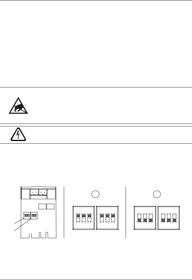
FPE-1000-CITY DIP Switch Settings
Note: Before installing the FPE-1000-CITY, set the DIP switches on the module to obtain the desired operation mode (Local Energy or Reverse Polarity Mode).
Refer to Figure 1 for the location and setting of DIP switches.
S1
S2
Reverse Reverse
ON |
|
ON |
|
|
|
1 |
2 |
3 |
1 |
2 |
3 |
S1 |
Local |
Local |
S2 |
||
BOSCH 
|
|
|
1 |
|
|
|
|
|
2 |
|
|
Reverse |
|
Reverse |
|
Reverse |
|
Reverse |
|
||||
ON |
|
ON |
|
ON |
|
ON |
|
||||
1 |
2 |
3 |
1 |
2 |
3 |
1 |
2 |
3 |
1 |
2 |
3 |
S1 |
Local |
Local |
S2 |
S1 |
Local |
Local |
S2 |
||||
Figure 1 |
DIP Switch Settings on the City Tie Plug-in Module |
||
|
|
|
|
Legend |
|
|
|
S1 |
|
Switch 1 |
Supervisory (SUP) |
S2 |
|
Switch 2 |
Fire Alarm (ALM) |
1 |
|
DIP switch setting for Reverse Polarity Mode |
|
2 |
|
DIP switch setting for Local Energy Mode |
|
F.01U.078.100 | 04 | 2011.11 |
Bosch Security Systems, Inc. |

FPE-1000-CITY en 5
FPE-1000-CITY |
|
S1 = SUP |
|
|
S2 = ALM |
|
DIP Switches |
|
|
|
|
|
|
|
1 |
2 |
3 |
1 |
2 |
3 |
|
|
|
|
|
|
|
Reverse Polarity Mode |
ON |
ON |
ON |
ON |
ON |
ON |
Local Energy |
OFF |
OFF |
OFF |
OFF |
OFF |
OFF |
Note: You may use different operation modes for the circuits. The DIP switch settings 1 to 3 for each switch (S1 and S2) must be set to the same position.
Mounting
1.Bring the plug-in module into position with the horizontal terminal lettering facing the front side of the control panel. Slide the plug-in module carefully into position along the guide rails (refer to Figure 2, Page 5, Item 1)
2.Ensure that the connections seat into the slot properly (refer to Figure 2, Page 5, Item 2).
3.Press down softly until the snap-fit hook locks into place (refer to Figure 2, Page 5, Item 3).
Fire |
|
|
Gas Alarm |
Power |
Supervisory |
|
Silenced |
Trouble |
|
DRILL |
RESET |
SILENCE |
ACK |
|
|
|
|
? |
|
@ _ |
|
|
|
|
. : , |
A↔a |
|
|
|
1
2
3 


1
Figure 2 Installing the FPE-1000-CITY City Tie Plug-in Module
To remove a plug-in module, press the snap-fit hook carefully from left to right and pull the board toward the panel front.
Wiring
No special wire is required for addressable loops. The wire can be untwisted, unshielded, solid or stranded as long as it meets the National Electric Code 760-51 requirements for power-limited fire protective signaling cables. Observe a maximum circuit resistance of 65 Ω.
Note: Use the appropiate DIP switch setting at the module to obtain the desired operation mode (refer to Figure 1,
Page 4).
Reverse Polarity Mode
The FPE-1000-CITY connects the FPA-1000 Analog Addressable Fire Panel to either a single set or a pair of dual leased telephone company (telco) lines in NFPA 72 Remote Station applications. The FPE-1000-CITY relays system alarm status information from the control panel to a monitoring station.
In normal conditions, the FPE-1000-CITY sends a steady current to a monitoring station. In an alarm condition, it reverses the polarity of the output current. The FPE-1000-CITY signals a trouble condition by interrupting the output voltage and current.
The default setting is fire alarm for circuit 1 and supervisory for circuit 2.
NOTICE!
Intended for connection to a polarity reversal circuit of a remote station receiving unit having compatible ratings.
Terminal |
Default setting |
|
- |
|
||
ALM - | + |
Fire Alarm |
ALM |
M |
|||
+ |
||||||
|
||||||
SUP - | + |
Supervisory |
|
- |
|
||
Legend |
|
|
SUP |
|
||
|
|
+ |
|
|||
M |
Monitoring Station |
|
|
|
||
|
|
Figure 3 |
Reverse Polarity Mode |
|||
Bosch Security Systems, Inc. |
F.01U.078.100 | 04 | 2011.11 |
Loading...