


 Loading...
Remote Command Center
FMR-1000-RCMD
|
|
|
|
|
|
|
|
|
|
|
|
en |
Installation and Operation Guide |
pt Manual de Instalação e Operação |
|
es |
Guía de Instalación y Operación |
|
|

FMR-1000-RCMD |
3 |
|
|
en |
Installation and Operation Guide |
5 |
|
|
|
es |
Guía de Instalación y Operación |
17 |
|
|
|
pt |
Manual de Instalação e Operação |
31 |
Bosch Security Systems, Inc. |
F.01U.078.098 | 3.0 | 2011.11 |

4 |
FMR-1000-RCMD |
|
|
F.01U.078.098 | 3.0 | 2011.11 |
Bosch Security Systems, Inc. |

Remote Command Center |
Table of Contents | en |
5 |
|
|
|
Table of Contents
1 |
Notice |
6 |
|
|
|
2 |
Scope of Delivery |
6 |
|
|
|
3 |
Device Description |
6 |
|
|
|
4 |
Mounting |
7 |
4.1 |
Removing the Cover Frame |
7 |
4.2 |
Surface Mounting |
7 |
4.3 |
Flush Mounting |
8 |
|
|
|
5 |
Wiring |
9 |
5.1 |
Option Bus Circuit Wiring Distance |
9 |
5.2 |
Wiring Connections |
9 |
5.3 |
Removing the Cover Frame for Service |
10 |
|
|
|
6 |
Inserting the Language Tab |
10 |
|
|
|
7 |
Address Setting |
11 |
|
|
|
8 |
Programming |
11 |
|
|
|
9 |
Operating |
12 |
9.1 |
LEDs and LCD Keypad |
12 |
9.2 |
Lamp Test |
14 |
9.3 |
Keypad Operations |
14 |
|
|
|
10 |
Troubleshooting |
15 |
|
|
|
11 |
Specifications |
15 |
11.1 |
Electrical |
15 |
11.1.1 |
Wiring Specification |
16 |
11.2 |
Mechanics |
16 |
11.3 |
Environmental Conditions |
16 |
11.4 |
Trademarks |
16 |
Bosch Security Systems, Inc. |
Installation and Operation Guide |
F.01U.078.098 | 3.0 | 2011.11 |

6 en | Notice Remote Command Center
1 |
Notice |
|
|
|
These instructions cover the installation of the Bosch FMR-1000-RCMD Remote Command |
|
|
Center in a fire system supervised by a Bosch FPA-1000 Analog Addressable Fire Panel or a |
|
|
Fire Alarm Control Panel with similar connection conditions. |
|
|
Install, test and maintain the FMR-1000-RCMD according to these instructions, NFPA 72, |
|
|
Local Codes, and the Authority Having Jurisdiction. Failure to follow these instructions may |
|
|
result in failure of the device to operate properly. Bosch Security Systems Inc. is not |
|
|
responsible for improperly installed, tested or maintained devices. |
|
|
Refer to FPA-1000- Installation and Operation Guide (P/N F.01U.174.607) for detailed wiring |
|
|
style requirements and complete programming instructions. |
|
|
|
|
NOTICE! |
|
|
NFPA 72 requires a complete system-wide functional test be performed following any |
|
|
modifications, repair, upgrades, or adjustments made to the system’s components, hardware, |
|
|
wiring, programming, and software/firmware. |
|
|
|
|
|
|
|
|
CAUTION! |
|
|
These instructions contain procedures to follow in order to avoid personal injury and damage |
|
|
to equipment. |
|
|
|
|
2 |
Scope of Delivery |
|
|
|
|
|
|
Description |
|
|
|
|
|
One Remote Command Center (in back box with cover frame) |
|
|
|
|
|
Tabs with different language versions for LED and key text |
|
|
|
|
|
One hardware pack |
|
|
|
|
|
One FMR-1000-RCMD Installation and Operation Guide |
|
|
|
3 |
Device Description |
|
|
|
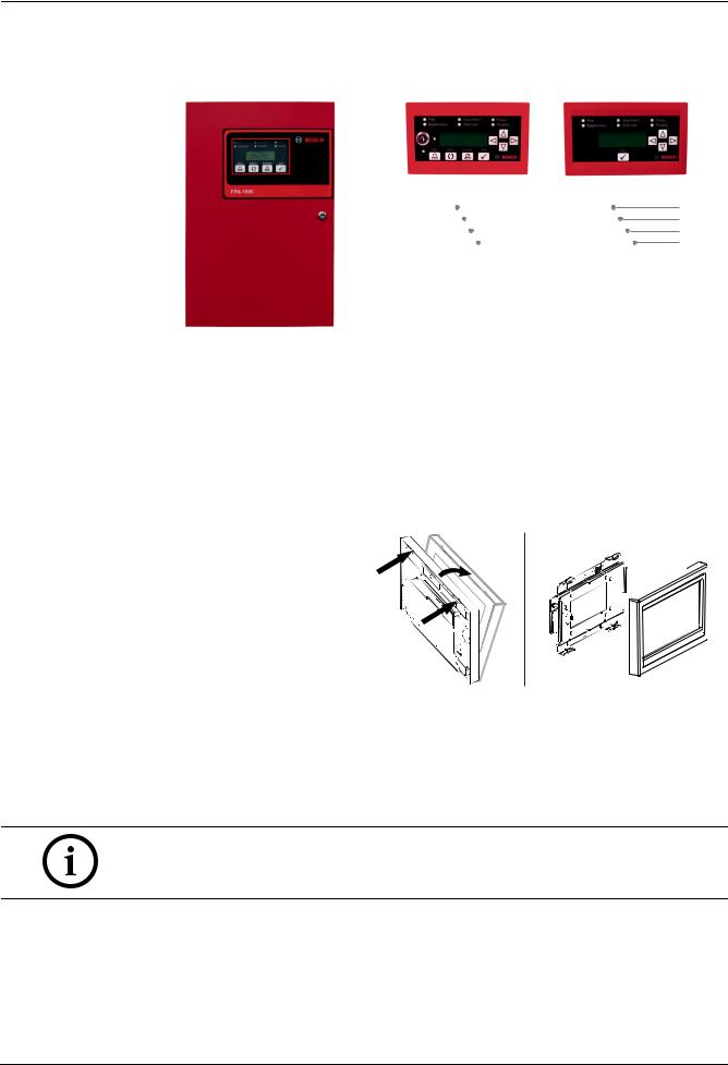
The Remote Command Center FMR-1000-RCMD is a four-wire LCD annunciator with system |
|
|
control capability. It shows the LEDs and LCD display identically to the panel’s and includes a |
piezo, scrolling buttons, and operation keys for acknowledge [ACK], drill, reset and silence. The scrolling functions and the acknowledge [ACK] key are accessible without restriction. The keys for reset, silence or drill can be enabled and disabled by the device key lock. In addition, the operation keys or all keys can be locked using DIP switches (refer to Table 7.1 on
Page 11).
The Remote Command Center features tabs with different language versions for LED and key text. The device allows for surface and semi-flush mounting.
Each FPA-1000 Analog Addressable Fire Panel supports up to a total of eight FMR-1000-RA Remote Annunciators and/or FMR-1000-RCMD Remote Command Centers.
F.01U.078.098 | 3.0 | 2011.11 |
Installation and Operation Guide |
Bosch Security Systems, Inc. |
Remote Command Center |
Mounting | en |
7 |
|
|
|
FPA-1000 |
FMR-1000-RCMD |
FMR-1000-RA |
||||||||
|
|
|
|
|
|
|
|
|
|
|
|
|
|
|
|
|
|
|
|
|
|
|
|
|
|
|
|
|
|
|
|
|
|
|
|
|
|
|
|
|
|
|
|
|
|
|
|
|
|
|
|
|
|
|
|
Figure 3.1 System Overview |
|
4 |
Mounting |
|
|
The Remote Command Center should be mounted no higher than shoulder height of the |
|
|
shortest person operating the system. |
|
4.1 |
Removing the Cover Frame |
|
|
The device comes with the |
|
|
mounting material and language |
|
|
tabs in separate bags. For |
|
|
removing the device’s cover |
|
|
frame from the annunciator unit, |
|
|
hold the assembly and unlock |
|
|
the snap-fit hooks on one side. |
|
|
Pull the cover frame off. |
|
|
|
Figure 4.1 Removing the Cover Frame (before Installation) |
4.2 |
Surface Mounting |
|
|
1. |
The back box provides three knockouts for 1/2 in. diameter conduit connectors in the |
|
|
back, bottom and top side (refer to Figure 4.2, Item 1). To get a clean break, remove the |
|
|
knockout from the inside of the box. |
|
NOTICE! |
|
|
To get a clean break, remove the knockout from the inside of the box. |
|
|
2. |
Install the back box with the arrow pointing up (refer to Figure 4.2, Item 2). |
|
3. |
Use the back box as a template to mark the location of the mounting holes (refer to |
|
|
Figure 4.2, Item 3). Provide an opening in the mounting surface for the wiring. Pre-start |
|
|
the screws. Do not secure the screws at this point. |
|
4. |
The built-in bubble level allows you to level horizontally without extra tools when |
|
|
securing the base (refer to Figure 4.2, Item 4). |
Bosch Security Systems, Inc. |
Installation and Operation Guide |
F.01U.078.098 | 3.0 | 2011.11 |

8 en | Mounting |
Remote Command Center |
|
|
Before mounting the unit, follow the instructions in
–Section 6 Inserting the Language Tab on Page 10
–Section 7 Address Setting on Page 11
–Section 5 Wiring on Page 9.
|
|
|
1 |
|
1.02 in. (26 mm) |
|
|
|
|
|
5 |
|
|
5 |
|
5.5 in. (140 mm) |
|
||
4.41 in. (112 mm) |
3 |
2 |
1 |
3 |
|
|
|
4 |
|
|
|
|
|
|
|
5 |
|
|
5 |
|
|
7.40 in. (188 mm) |
|
|
1.02 in. (26 mm) |
|
|
7/8 in. (20 mm) |
|
|
|
|
1 |
|
Figure 4.2 Back Box of the FMR-1000-RCMD Remote Command Center
Legend
1 Knockout for 1/2 in. conduit connector in the in the back, bottom and top side
2Arrow pointing up
3 Mounting holes for surface mounting
4Bubble level
5Fixing points for annunciator unit (4 screws)
4.3 |
Flush Mounting |
For flush mounting, use a 3 gang electrical box. Refer to
Figure 4.3 to select the mounting holes.
Before mounting the unit, follow the instructions in
–Section 6 Inserting the Language Tab on Page 10
–Section 7 Address Setting on Page 11
–Section 5 Wiring on Page 9.
1.82 in. |
1.82 in. |
(46 mm) |
(46 mm) |
|
|
1 |
1 |
1 |
3.54 in. (90 mm) |
3.19 in. (81 mm) |
|
|
|
|
|
1 |
1 |
1 |
Figure 4.3 |
Flush Mounting |
|
|
|
Legend |
|
|
|
|
1Mounting holes for flush mounting
F.01U.078.098 | 3.0 | 2011.11 |
Installation and Operation Guide |
Bosch Security Systems, Inc. |
Remote Command Center Wiring | en 9
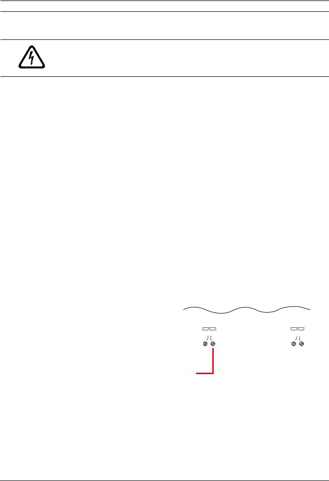
5 Wiring
DANGER!
Explosion and burn hazard. Do not short terminals.
Incorrect connections can result in damage to the unit and personal injury.
Before servicing this equipment, remove all power connections.
5.1 |
Option Bus Circuit Wiring Distance |
|
Use four conductor, 18 AWG (0.8 mm2) or larger wire to connect Option Bus devices to the |
|
FACP. The total length of wire connected to the Option Bus terminals must not exceed 4000 ft |
|
(1219 m), regardless of the wire gauge used. |
|
The maximum length between any one device and the panel terminals depends on the current |
|
drawn on the branch that the device is on. The current draw on a particular branch can be |
|
found by adding together the individual current draws of each device connected to the |
|
branch. Refer to FPA-1000 Installation and Operation Guide (P/N F.01U.173.607) for detailed |
|
wire length calculations. |
5.2 |
Wiring Connections |
|
|
|
|
|
|
|
|
|
|
|
|
|
|
|
|
|
|
|
|
|||
|
|
The FMR-1000-RCMD is powered by either of the following power outputs from the FPA-1000: |
||||||||||||||||||||||
|
|
– |
12 V DC power (Option bus) |
|
|
|
|
|
|
|
|
|
|
|
|
|
|
|
|
|
|
|
|
|
|
|
– |
24 V FWR unfiltered Aux power output |
|
|
|
|
|
|
|
|
|
|
|
|
|
|
|
|
|
|
|||
|
|
or UL listed external power supply with common reference ground with the FPA-1000: |
||||||||||||||||||||||
|
|
– |
12 V DC power |
|
|
|
|
|
|
|
|
|
|
|
|
|
|
|
|
|
|
|
|
|
|
|
– |
24 V DC power. |
|
|
|
|
|
|
|
|
|
|
|
|
|
|
|
|
|
|
|
|
|
|
|
To wire the FMR-1000-RCMD: |
|
|
|
|
|
|
|
|
|
|
|
|
|
|
|
|
|
|
|
|
||
|
1. |
Power down the control panel. |
|
|
|
|
|
|
|
|
|
|
|
|
|
|
|
|
|
|
|
|
||
|
2. |
Route the wiring from the FACP to the annunciators. |
|
|
|
|
|
|
|
|
|
|||||||||||||
|
3. |
Bring the wiring through one of the knockouts in the annunciator’s base (surface |
||||||||||||||||||||||
|
|
|
mounting) or the 3 gang electrical box (flush mounting). Refer to Figure 4.2 on Page 8 for |
|||||||||||||||||||||
|
|
|
wire entrance location in the back box. |
|
|
|
|
|
|
|
|
|
|
|
|
|
|
|
|
|
|
|||
|
|
|
|
|
|
|
|
|
|
|
|
|
|
|
|
|
|
|
|
|
|
|
|
|
|
|
Legend |
|
|
|
|
|
|
|
|
|
|
|
|
|
|
|
|
|
|
|
|
|
|
|
|
|
|
|
|
|
|
|
|
|
|
|
|
|
|
|
|
|
|
|
|
|
|
|
|
|
GND |
Ground |
|
|
|
|
|
|
|
P3 |
|
|
P7 |
|
|||||||||
|
|
|
|
|
|
|
|
|
|
|
|
|
|
|
||||||||||
|
|
|
|
|
|
|
|
GNDPWR+ |
Y G |
|
||||||||||||||
|
|
V+/PWR |
Power supply |
|
|
|||||||||||||||||||
|
|
|
|
|
|
|
|
|
|
|
|
|
|
|
|
|
|
|
|
|
|
|||
|
|
|
|
|
|
|
|
|
|
|
|
|
|
|
|
|
|
|
|
|
|
|
|
|
|
|
Y |
|
Yellow, Data OUT |
|
|
|
|
|
|
|
|
|
|
|
|
|
|
|
|
|
|
|
|
|
|
|
|
|
|
|
|
|
|
|
|
|
|
|
|
|
|
|
|
|
|
|
||
|
|
|
|
|
|
|
|
|
|
|
|
|
|
|
|
|
|
|
|
|
|
|
|
|
|
|
G |
|
Green, Data IN |
|
|
|
|
|
|
|
|
|
|
|
|
|
|
|
|
|
|
|
|
|
|
|
|
|
Y |
|
|
|
|
|
|
|
|
|
|
|
|
|
|
|
|
|
||
|
|
|
|
|
|
|
|
|
|
|
|
|
|
|
|
|
|
|
|
|||||
|
|
P3 |
Power supply |
|
|
|
|
|
|
|
|
|
|
|
||||||||||
|
|
|
|
|
|
|
|
|
|
|
|
|
|
|
|
|
|
|||||||
|
|
|
|
connection |
|
|
G |
|
|
|
|
|
|
|
|
|
|
|
|
|
|
|||
|
|
|
|
|
|
|
|
|
|
|
|
|
|
|
|
|
|
|
|
|||||
|
|
|
|
|
|
B |
|
|
|
|
|
|
|
|
|
|
|
|
|
|
||||
|
|
|
|
|
|
|
|
|
|
|
|
|
|
|
|
|
|
|
|
|||||
|
|
|
|
|
|
|
R |
|
|
|
|
|
|
|
|
|
||||||||
|
|
P7 |
Data connection |
|
|
|
|
|
|
|
|
|
|
|
||||||||||
|
|
Figure 5.1 Wiring Connections |
|
|
|
|
|
|
|
|
|
|||||||||||||
|
|
|
|
|
|
|
|
|
|
|
|
|
|
|||||||||||
|
|
|
|
|
|
|
|
|
|
|
|
|
|
|
|
|
|
|
|
|
|
|
|
|
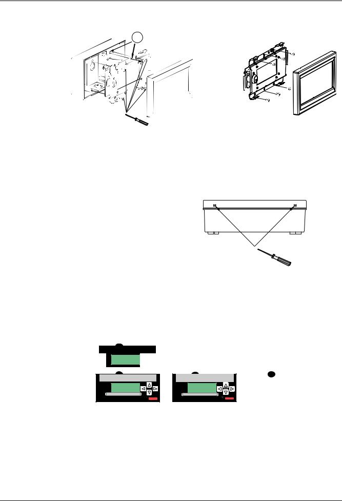
4.Connect the wiring to the FMR-1000-RCMD terminals. Refer to Figure 5.1.
5.For surface mounting with back box: Secure the base. Use the bubble level to make sure that the back box is perfectly horizontal. Refer to Figure 4.2 on Page 8.
6.Fasten the annunciator unit with the four mounting screws using a Phillips (crossheaded) screwdriver. Secure the screw for the earth ground connection. Refer to
7.Place the cover frame onto the base along the top side. Press the bottom part until it snaps into place.
Bosch Security Systems, Inc. |
Installation and Operation Guide |
F.01U.078.098 | 3.0 | 2011.11 |
10 en | Inserting the Language Tab |
|
|
|
|
|
|
|
Remote Command Center |
|
|
|
|
|
|
|
|
|
|
|
|
|
|
|
|
|
|
|
|
|
|
|
|
|
|
|
|
|
|
|
|
|
|
|
|
|
|
|
|
|
|
|
|
|
|
|
|
|
|
|
|
|
|
|
|
|
|
|
|
|
|
|
|
|
|
|
|
|
|
|
|
|
|
|
|
|
|
|
|
|
|
|
|
|
|
|
|
|
|
|
Figure 5.2 Position of Mounting Screws and Earth Ground Screw
When the device is powered on, the system performs a selftest. The routine includes checking of all interfaces, address switches, LEDs, LCD, buzzer, keys, current consumption, and lamp test.
5.3 |
Removing the Cover Frame for Service |
For removing the device’s cover frame when the annunciator unit is already mounted, insert a small flathead screwdriver in each slot at the bottom or at the top of the frame. Press up and pull the cover frame off.
Figure 5.3 Removing the Cover Frame (after Installation)
6 |
Inserting the Language Tab |
|
|
|
For different language versions of LED and key lettering, use the tabs provided with the |
||
|
FMR-1000-RCMD. |
|
|
|
1 |
2 |
3 |
Fire |
Gas Alarm |
Power |
Supervisory |
Silenced |
Trouble |
Fire |
Gas Alarm |
Power |
Supervisory |
Silenced |
Trouble |
Gas Alarm |
Silenced |
Fire |
Gas Alarm |
Power |
Supervisory |
Silenced |
Trouble |
Figure 6.1 Inserting the Language Tab
1.Insert the tab carefully in the slot at the top of the keypad.
2.Slide the tab down carefully until it is completely flush with the keypad.
3.For tab removal, carefully pull upwards at the strap.
F.01U.078.098 | 3.0 | 2011.11 |
Installation and Operation Guide |
Bosch Security Systems, Inc. |
Remote Command Center Address Setting | en 11
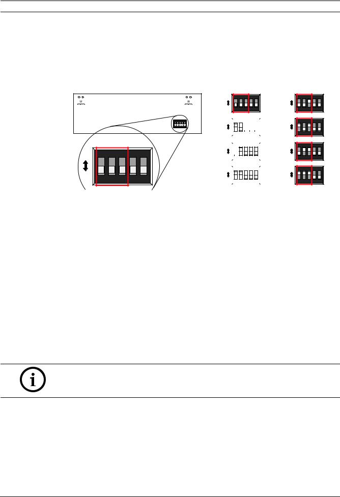
7 Address Setting
Each FMR-1000-RCMD connected to the Option Bus of the FPA-1000 must be set to a unique Option Bus address ranging from 16 to 23. The devices must also be programmed at the control panel (refer to FPA-1000 Installation and Operation Guide (P/N F.01U.173.607).
The address is set using the DIP switches at the main board of the annunciator unit. Refer to
Table 7.1.
|
|
|
|
|
|
|
|
G |
Y |
GNDPWR+ |
|
|
P7 |
|
P3 |
ON |
|
|
|
DIP |
1 |
2 |
3 |
4 |
5 |
ON |
ON |
|
|
DIP |
|
|
|
|
|
|
|
OFF |
1 |
2 |
3 |
4 |
5 |
|
|||||
Figure 7.1 |
Address Setting |
|
|||
ON |
ON |
|
|
|
DIP |
16 |
OFF |
1 |
2 |
3 |
4 |
5 |
|
ON |
ON |
|
|
|
DIP |
17 |
||
|
|
|
|
|
||||
|
|
|
|
|
|
|
|
|
OFF |
1 |
2 |
3 |
4 |
5 |
|
|
|
|
|
|
|
|
|
|
18 |
|
ON |
|
|
|
|
|
|
|
|
ON |
|
|
|
DIP |
||||
|
|
|
|
|
||||
|
|
|
|
|
|
|
|
|
OFF |
|
1 |
2 |
3 |
4 |
5 |
|
|
ON |
|
|
|
|
|
|
19 |
|
|
ON |
|
|
|
DIP |
|||
|
|
|
|
|
||||
|
|
|
|
|
|
|
|
|
OFF |
|
1 |
2 |
3 |
4 |
5 |
|
|
|
|
|
|
|
|
|
|
|
ON |
ON |
|
|
|
DIP |
20 |
OFF |
1 |
2 |
3 |
4 |
5 |
|
ON ON |
|
|
|
DIP |
21 |
OFF 1 |
2 |
3 |
4 |
5 |
|
ON ON |
|
|
|
DIP |
22 |
|
OFF |
1 |
2 |
3 |
4 |
5 |
|
ON ON |
|
|
|
DIP |
23 |
|
OFF |
1 |
2 |
3 |
4 |
5 |
|
Option Bus |
DIP 1 |
DIP 2 |
DIP 3 |
DIP 4 |
DIP 5 |
|
Address |
|
|
|
|
|
|
|
|
|
|
|
|
|
16 |
OFF |
OFF |
OFF |
OFF position: |
OFF position: |
|
|
|
|
|
Control keys |
Key lock |
|
17 |
ON |
OFF |
OFF |
|||
|
|
|
|
are locked. |
active. |
|
18 |
OFF |
ON |
OFF |
|||
|
|
|||||
|
|
|
|
|
|
|
19 |
ON |
ON |
OFF |
ON position: |
ON position: |
|
|
|
|
|
|||
20 |
OFF |
OFF |
ON |
|||
All keys are |
Key lock |
|||||
|
|
|
|
|||
21 |
ON |
OFF |
ON |
locked. |
bypassed. |
|
|
|
|
|
|
|
|
22 |
OFF |
ON |
ON |
|
|
|
|
|
|
|
|
|
|
23 |
ON |
ON |
ON |
|
|
|
|
|
|
|
|
|
Table 7.1 DIP Switch Function
The DIP switch 4 allows for locking the control keys (drill, reset and silence) in OFF position and for locking all keys in ON position.
The DIP switch 5 enables the device’s key lock in OFF position and bypasses the key lock in ON position.
NOTICE!
Each Option Bus device must have its own address, and each address can support only one device. Ensure that there are no duplicate addresses on the bus.
8 |
Programming |
All Remote Annunciators and Remote Command Centers have to be configured as elements connected to the Option Bus.
The FPA-1000 enables various programming approaches:
–On-site at the front panel to program another panel, but not all parameters can be programmed
–On-site through a Web server using a laptop (connected to the panel with CAT5 cable)
–Remote, using a Web page and a dial-up connection
Bosch Security Systems, Inc. |
Installation and Operation Guide |
F.01U.078.098 | 3.0 | 2011.11 |
12 en | Operating |
Remote Command Center |
|
|
–Remote, using a Web page and an Ethernet connection.
For front panel programming, the system provides an auto learn function, allowing the installer to configure the system quickly and easily in default mode.
Using a local laptop or remote access through a communicator, the programming is carried out by means of browser-based user interface (virtual keypad).
Refer to the FPA-1000 Installation and Operation Guide (P/N F.01U.173.607) for detailed programming instructions.
9 |
Operating |
9.1 |
LEDs and LCD Keypad |
|
The LEDs on the Remote Command Center follow the global system status (refer to |
Table 9.1). In addition, a communication fault on the Option Bus is indicated by the trouble LED flashing at 1 Hz (refer to Section 10 Troubleshooting on Page 15).
Legend
1LEDs
2 Device key
3 LCD screen
4Scroll keys
5Keys for Drill, Reset, Silenced, and Acknowledge [ACK]
1
2
3 
5
1
4
5
|
|
|
|
|
Figure 9.1 Front View FMR-1000-RA |
|
|
|
|
|
|
|
|
|
|||
|
LED |
System Status |
|||
|
|
|
|
|
|
Fire |
|
|
On |
Whenever the system registers a fire alarm and is not reset |
|
Red |
|
|
|
|
|
|
|
Off |
– If no alarm registered |
||
|
|
|
|
– |
After resetting |
|
|
|
|
|
|
Gas Alarm |
|
|
On |
When the system registers a gas alarm and is not reset |
|
Blue |
|
|
|
|
|
|
|
Off |
– If no gas alarm registered |
||
|
|
|
|
– |
After resetting |
|
|
|
|
|
|
Power |
|
|
On |
If AC power is applied to the panel |
|
Green |
|
|
|
|
|
|
|
Flashing 1) |
When AC power fails and the unit operates from battery power |
||
|
|
|
Off |
When no power (AC or battery) is applied |
|
|
|
|
|
|
|
Supervisory |
|
|
On |
When the system registers a supervisory condition |
|
Yellow |
|
|
|
|
|
|
|
Off |
When no supervisory condition is registered |
||
|
|
|
|
|
|
Silenced |
|
|
On |
– When an alarm or trouble condition is silenced manually by the user |
|
Yellow |
|
|
|
– If the system auto-silence timer expires |
|
|
|
|
|
|
|
|
|
|
Off |
– When no condition is silenced |
|
|
|
|
|
– When a silenced condition is corrected |
|
|
|
|
|
|
|
F.01U.078.098 | 3.0 | 2011.11 |
Installation and Operation Guide |
Bosch Security Systems, Inc. |

Remote Command Center Operating | en 13
LED |
|
System Status |
|
|
|
|
|
Trouble |
On |
– |
When the panel is initializing |
Yellow |
|
– When the panel registers a trouble condition from a point, or the panel |
|
|
|
– |
When inputs or outputs or other elements are bypassed |
Flashing 1) – When the panel is not operating
–When walk test is in progress
Off |
– When no trouble condition exists |
–When the panel is resetting
1)LED flash rate is 1 Hz (0.5 s on, 0.5 s off).
Table 9.1 LED Operation
Display
The FMR-1000-RCMD Remote Command Center uses an 80-character (4 lines x 20 characters) wide viewing-angle LCD display. The display includes a long-life LED backlight. The backlight is controlled by the panel, or locally turned on upon any key press and turned off after 30-second time-out without key press. Even when AC power is lost, the LED backlight remains lit if a user is operating the keypad.
Piezo Sounder
The FMR-1000-RCMD Remote Command Center has a piezo that provides audible indication of the system status. Refer to Table 9.2 for piezo modes when FMR-1000-RCMD is controlled by the panel:
Piezo Operation |
System Status |
|
|
Silent |
The panel is in a normal state (no alarm, supervisory or trouble |
|
condition). The panel was silenced or acknowledged after an off- |
|
normal condition. |
|
|
Continuous beep |
The panel is in fire alarm condition. |
|
|
Periodic beep |
The panel is in gas alarm condition. |
(0.5 s every 2 s) |
|
|
|
Periodic beep |
The panel is in supervisory condition. |
(0.5 s every 4 s) |
|
|
|
Periodic beep |
The panel is in trouble condition or a communication fault exists |
(0.5 s every 10 s) |
on the Option Bus. |
|
|
Short beep |
With every valid key press. |
|
|
Table 9.2 Piezo Operation with FMR-1000-RCMD Panel Controlled
In case of multiple piezo activation, the system status with highest priority is indicated. If the Remote Command Center is not controlled by the panel or during a communication fault, refer to Table 9.3 for piezo modes:
Piezo Operation |
System Status with FMR-1000-RA Controlled Locally |
|
|
Periodic beep |
A communication fault exists on the Option Bus. |
(0.5 s every 10 s) |
|
|
|
Table 9.3 Piezo Operation with FMR-1000-RCMD Controlled Locally
Bosch Security Systems, Inc. |
Installation and Operation Guide |
F.01U.078.098 | 3.0 | 2011.11 |

14 en | Operating Remote Command Center
9.2 |
Lamp Test |
|
A lamp test is accomplished by pressing and holding the acknowledge [ACK] key for more |
|
than 3 seconds. All LEDs on the FMR-1000-RA are turned on and the LCD display is filled with |
|
black blocks when the lamp test starts. As soon as the acknowledge [ACK] key is released, the |
|
revision number, Option Bus address, and key lock status appear on LCD display for |
|
3 seconds. Then the LEDs and the LCD display return to normal working mode (controlled by |
|
the panel). |
9.3 Keypad Operations
With the key lock in the locked position, the user can use the scroll keys only for navigating the LCD display and operate the acknowledge [ACK] key. Upon an invalid key press, the display shows “KEY LOCKED” for 3 seconds. Refer to Table 7.1 on Page 11 for key lock bypass option.
With either the key lock in unlocked position or the DIP switch setting for the key lock bypassed, the user may operate any of the device’s keys.
View Status
With no alarms or troubles in the system, the display message is "SYSTEM NORMAL" or "SYSTEM NORMAL DAY" along with the current date and time.
During initialization by start-up or re-configuration, the screen indicates "System Initializing”. The panel shows the “System Resetting” screen upon reset, until the system returns to the normal supervising condition.
If PAS or Pre-signal is turned on, the screen indicates “SYSTEM NORMAL DAY”.
Any off-normal conditions are shown in groups classified as fire alarm, gas alarm, supervisory and trouble.
Use the arrow keys to view events or conditions in the same group. Up and down keys move the user to the previous or next event. The left and right keys switch to other groups.
NOTICE!
For system display information, refer to FPA-1000 Installation and Operation Guide
(P/N F.01U.173.607).
Acknowledge
During an alarm, pressing the acknowledge [ACK] key turns off the piezo that is sounding on an annunciator. All the ongoing events or conditions are marked as “Acknowledged”. The 24-hour trouble reminder timer starts. Any trouble event not cleared within 24 hours is sent again and the piezo begins to beep again.
If a fire input point configured as "PAS enabled" (with global PAS enabled) is activated, pressing the acknowledge [ACK] key within 15 seconds after a PAS activation starts the investigation timer. This allows the user to investigate the fire alarm or take other appropriate actions until the timer expires.
An acknowledgement operation can also be initiated by the activation of an input point configured as an acknowledge type.
Silence
Pressing the silence key performs all functions of the acknowledge operation.
When the silence operation is initiated, the panel goes into a “Silenced” status and the “Silenced" LED lights. The piezos on all keypads and annunciators turn off. All outputs are silenced if configured as “Silenceable”. NACs play the “Silenced” pulse for the programmed
F.01U.078.098 | 3.0 | 2011.11 |
Installation and Operation Guide |
Bosch Security Systems, Inc. |

Remote Command Center |
Troubleshooting | en 15 |
|
|
pattern, or they fully de-energize, as defined by the global option “Silence Config”. Strobes continue flashing.
If programmed, the panel transmits a silence report to the central station.
If the panel is already silenced, pressing [SILENCE] again causes an unsilence command in the panel. Silence operation does not reset the alarm status and does not return the activated input to normal service. Any new alarm reactivates any silenced outputs.
Trouble Reminder
If any events are not cleared within 24 hours after the [SILENCE] or [ACK] key was pressed, the panel turns on the piezo again and events are transmitted to the central station again.
Reset
Pressing the reset key turns off the piezo and all activated or silenced outputs. The reset operation turns off auxiliary power AUX/RST for 5 seconds, and activates the global resetting zone. All alarms, supervisories, and troubles caused by activation of SLC points are cleared. Then the panel tries to reset all points that are in off-normal status. Not all system trouble conditions are affected by the reset operation. If programmed, the panel transmits a reset report to the central station.
Any alarm or trouble that exists after a reset causes the system to sound again.
Drill
To activate the drill operation, the [DRILL] key must be pressed twice to prevent accidental activation. Pressing the key once the system prompts for confirmation. Pressing the [DRILL] key again turns on all unbypassed NACs and drillable relay outputs.
The drill operation stops if the reset key is pressed, or it is automatically cancelled if the operation was started for a programmed time. A system reset is automatically performed by stopping the drill so that the panel and all field devices restore to their normal operation.
If programmed, a drill start report and a drill stop report are transmitted to the central station.
10 |
Troubleshooting |
|
|
|
|
|
|
|
|
|
|
|
|
Display |
LED |
Piezo |
Description |
|
|
|
|
|
|
|
|
NOT PROGRAMMED |
0.5 s on/ |
0.5 s every |
No communication activities on |
|
|
|
0.5 s off |
10 s |
the device address. |
|
|
|
|
|
|
|
|
NO COMMUNICATION |
0.5 s on/ |
0.5 s every |
After 60 seconds of no |
|
|
|
0.5 s off |
10 s |
communication activities on any |
|
|
|
|
|
Option Bus address. |
|
|
|
|
|
|
|
|
COMMUNICATION OK |
off |
off |
Communication on the device |
|
|
|
|
|
address; no text received yet. |
|
|
|
|
|
|
11 |
Specifications |
|
||
11.1 |
Electrical |
|
||
|
|
|
|
|
|
|
Operating voltage |
Nominal 12 V DC or 24 V DC/FWR |
|
|
|
|
|
|
|
|
Current consumption at 12 V DC |
|
|
|
|
|
|
|
|
|
– |
Standby current |
25 mA maximum (only Power LED on) |
|
|
|
|
|
|
|
– |
Alarm current |
150 mA maximum (with annunciator lit and piezo |
|
|
|
|
on) |
|
|
|
|
|
Bosch Security Systems, Inc. |
Installation and Operation Guide |
F.01U.078.098 | 3.0 | 2011.11 |
Loading...