


F220 Series Detectors with
F220-B6RS Base
Installation Manual
|
|
|
|
|
|
|
|
en |
English manual |
|
|

2 en | Legal |
F220 Series Detectors with F220-B6RS Bases |
|
|
1 Legal
1.1Trademarks
CleanMe® is a registered trademark of GE Interlogix in the United States and/or other countries.
Chamber Check® is a registered trademark of Bosch Security Systems, Inc. in the United States.
Chambermaid™ is a trademark of Bosch Security Systems, Inc. in the United States.
ENVI-RO-TECH™ is a trademark of Tech Spray L.P.
TECHSPRAY® is a registered trademark of Tech Spray L.P.
1.2Required Maintenance and Testing
Keep the detector calibrated for proper operation. NFPA 72, The National Fire Alarm Code, recommends performing calibration tests at installation, then every other year. Depending on local regulations, calibration testing might be required more than once a year.
Perform functional testing yearly.
NOTE! Notify all concerned parties before any
i maintenance or testing of the fire alarm system and upon completion of these activities.
Test the calibration (to meet NFPA 72) using either the magnet test or measuring the calibration with a calibrated product from No Climb Products Ltd. Quickly determine the calibration by a visual inspection of the detector’s LED (refer to Section 4.4 Flash Rate and Trouble Indication on page 24). These tests confirm whether or not the detector is within its factory marked calibration range.
At least once a year vacuum or wipe the external part of the detector clean. Pay particular attention to the detector screens in areas of heavy insect activity or dust. To clean the chamber,
F.01U.029.847 | -01 | 2007.02 |
Installation Manual |
Bosch Security Systems, Inc. |

F220 Series Detectors with F220-B6RS Bases |
General Information | en 3 |
||
|
|
||
|
use a can of clean, dry compressed air (such as TECHSPRAY |
||
|
ENVI-RO-TECH Duster) which is available at office and alarm |
||
|
supply stores. Shorten the plastic tube that comes with the |
||
|
compressed air to about 2 in. (5 cm). Place the tube or needle |
||
|
valve through the Chambermaid valve in the bottom of the |
||
|
detector (refer to Figure 2.2 on page 6). |
||
|
|
||
i |
NOTE! Do not paint the detectors. Paint or other foreign |
||
matter covering the detector can prevent smoke |
|||
detection. |
|
||
|
|
|
|
2 |
General Information |
|
|
|
This document covers mounting, wiring, power requirements, |
||
|
testing, and maintenance for the F220-B6RS Detector Bases |
||
|
and the F220 Series Heat and Photoelectric Smoke Detectors. |
||
|
Install them according to NFPA 72. |
|
|
|
|
||
i |
NOTE! For proper system installation, read and |
||
understand NFPA 72 before installation. |
|||
|
|||
|
|
|
|
For installation guidelines, refer to Installation Considerations for Smoke and Fire Detectors (P/N: 26715).
2.1F220-B6RS Detector Bases
The F220-B6RS is a four-wire base with a Form A alarm relay and a built-in sounder. Other bases (two-wire and four-wire without built-in sounders) are available. Refer also to the F220 Series Detectors with F220-B6/C/E/R Installation Instructions (P/N: 4998138694) and the F220-B6PS/M Installation Instructions (P/N: 4998149982).
2.1.1Compatible Control Panels
The F220-B6RS is a four-wire base compatible with all UL Listed four-wire control panels. Refer to the control panel
Bosch Security Systems, Inc. |
Installation Manual |
F.01U.029.847 | -01 | 2007.02 |

4 en | General Information |
F220 Series Detectors with F220-B6RS Bases |
|
|
manufacturer’s installation instructions for proper end-of-line (EOL) resistor selection.
2.1.2Base Features
|
13 |
|
11 |
12 |
|
10 |
||
|
||
12 |
15 |
|
|
||
13 |
8 |
|
|
||
7 |
3 |
|
4 |
2 |
|
5 |
||
1 |
||
4 |
||
3 |
|
|
P |
|
|
ID |
2 |
|
|
1 |
|
N |
|
|
O |
|
6
12
13
14
9
13
12
1. |
Terminal 1 |
9. |
Remote Terminal (c) |
2. |
Terminal 2 |
10. |
Tamper Tab (Locking Bar) |
3. |
Terminal 3 |
11. |
Tamper Tab (Locking Bar |
4. |
Terminal 4 |
|
Mount) |
5. |
Terminal 5 |
12. |
Alignment Key (4 places) |
6. |
DIP Switches |
13. |
Snap Lock (4 places) |
7. |
Resettable Auxiliary Power |
14. |
Sounder |
|
Positive (+) In and Out |
15. |
Earth Shield Terminal |
|
Terminals (b1 and b2) |
|
(optional) |
8. |
Resettable Auxiliary Power |
|
|
|
Negative (-) In and Out |
|
|
|
Terminal (a1/a2) |
|
|
Fig. 2.1 Base Features
F.01U.029.847 | -01 | 2007.02 |
Installation Manual |
Bosch Security Systems, Inc. |

F220 Series Detectors with F220-B6RS Bases |
General Information | en 5 |
|
|
2.2F220 Series Detectors
2.2.1About F220 Series Detector Heads
The F220 Series Detector Heads listed inTable 2.1 each require an F220-B6 Series Base.
WARNING! The F220-PTHC detects carbon monoxide
!(CO) as a component of a fire. Do not use the F220-PTHC as a stand-alone CO detector.
F220-135 |
Electronic heat detector 135°F (57°C), fixed |
|
temperature and rate-of-rise |
||
|
||
|
|
|
F220-135F |
Electronic heat detector 135°F (57°C), fixed |
|
|
temperature only |
|
|
|
|
F220-190F |
Electronic heat detector 190°F (88°C), fixed |
|
temperature only |
||
|
|
|
F220-P |
Photoelectric smoke detector |
|
|
|
|
F220-PTH |
Photoelectric smoke detector with integral 135°F |
|
(57°C) heat sensor |
||
|
||
|
|
|
|
Photoelectric smoke detector with integral 135°F |
|
F220-PTHC |
(57°C) heat sensor and CO enhanced smoke |
|
|
detection |
|
|
|
Table 2.1 F220 Series Detector Heads
Bosch Security Systems, Inc. |
Installation Manual |
F.01U.029.847 | -01 | 2007.02 |
6 en | General Information |
F220 Series Detectors with F220-B6RS Bases |
|
|
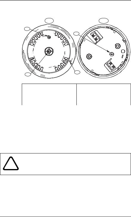
2.2.2F220 Series Detector Features
1 |
5 |
2 |
|
|
6 |
4
3
1. Front of detector |
4. Unlocking port |
2.Light-emitting diode (LED) 5. Back of detector
3. Thermistor |
6. Chambermaid location |
(heat detectors only) |
|
|
|
Fig. 2.2 Detector Features |
|
2.2.3F220 Series Heat Detector Heads
The F220 Heat Detector Heads can be identified by color coding (refer to Table 2.2).
F220-135 |
No circle around the thermistor |
|
|
F220-135F |
A gray circle around the thermistor |
|
|
F220-190F |
A black circle around the thermistor |
|
|
Table 2.2 Distinguishing Heat Detectors
WARNING! The F220-135, F220-135F and F220-190F are
!not life safety devices. Use them with F220-B6 Series bases to provide general property protection.
F.01U.029.847 | -01 | 2007.02 |
Installation Manual |
Bosch Security Systems, Inc. |

F220 Series Detectors with F220-B6RS Bases |
General Information | en 7 |
|
|
2.2.4F220 Series Smoke Detector Heads
The F220 Series Smoke Detector Heads are UL Listed, openarea photoelectric smoke detectors that work with commercial fire protective signaling systems and household fire warning systems. Select the appropriate mounting base to configure the detectors for two-wire or four-wire versions (refer to
Section 2.1 F220-B6RS Detector Bases on page 3).
To verify power to the detector and a functioning smoke sampling circuitry, a dual color LED indicator flashes green every eight seconds when operating normally. It flashes once every four seconds when a trouble condition exists. If the detector determines an alarm condition exists, the LED changes from flashing green to steady red. The detector returns to normal after the alarm condition is cleared and power is interrupted.
Throughout its normal life cycle, the smoke detector monitors and periodically adjusts itself to keep the sensitivity at its factory calibrated level. When excessively dirty, the detector’s LED flash rate changes from an eight second flash rate to a four second rate. If CleanMe is selected, the detector sends a CleanMe signal to the compatible control panel to indicate a dirty smoke detector.
Refer to Section 4.3 Set CleanMe Feature on page 24.
2.3Technical Specifications
2.3.1General Specifications
Air Velocity |
4000 ft/min (1200 m/min) maximum |
|
|
Operating |
+32°F to 100°F (0°C to 38°C) |
Temperature |
|
|
|
Relative |
0% to 95% (non-condensing) |
Humidity |
|
|
|
Table 2.3 Specifications - Detectors and Bases
Bosch Security Systems, Inc. |
Installation Manual |
F.01U.029.847 | -01 | 2007.02 |

8 en | Install the Bases F220 Series Detectors with F220-B6RS Bases
2.3.2 |
Base Specifications |
|
|
|
|
|
Alarm Current (only base current, detector current excluded) |
|
|
|
|
|
F220-B6RS (with |
45 mA at 24 VDC |
|
steady sounder and |
50 mA maximum at 30 VDC |
|
relay): |
|
|
|
|
|
F220-B6RS (with |
30 mA at 24 VDC |
|
separately powered |
35 mA maximum at 30 VDC |
|
sounder only): |
|
|
|
|
|
NAC Current |
30 mA at 24 VDC |
|
|
|
|
Standby Current |
10 mA maximum at 30 VDC |
|
|
|
|
Voltage |
10.0 VDC to 30.0 VDC |
|
|
|
Table 2.4 F220-B6RS Detector Base Specifications
2.3.3Detector Specifications
Current
Alarm: |
35 mA maximum at 32 VDC |
|
|
Standby: |
0.12 mA maximum |
|
|
Startup: |
0.12 mA maximum |
|
|
Powerup Time |
22 second maximum |
|
|
Rate of Rise |
|
|
|
F220-135: |
15°F/min (9°C/min) or greater |
|
|
Table 2.5 F220 Series Detector Heads Specifications
2.4Electrical Supervision
When the F220-B6RS Bases are wired according to the instructions in this document, the control panel initiates a trouble signal when a detector is removed from its base, providing tamper protection. An EOL power supervision module, such as a D275 or an F220-B6E Power Supervision Base and an EOL resistor as specified by the control panel manufacturer, supervises power.
3 Install the Bases
3.1Mount the Bases
With the exception of the F220-B6E base, all four-wire bases can be used in any combination within a loop. One F220-B6E
F.01U.029.847 | -01 | 2007.02 |
Installation Manual |
Bosch Security Systems, Inc. |

F220 Series Detectors with F220-B6RS Bases |
Install the Bases | en 9 |
|
|
Power Supervision Base can be used as the last base on a loop in four-wire systems to provide power supervision.
NOTE! Follow NFPA 72 guidelines for mounting locations. i For commercial and industrial installations, 30 ft (9 m)
spacing between smoke detectors is recommended.
1.Release the mounting skirt from the mounting base. Use a screwdriver at the location of the snap locks (refer to Figure 2.1, item 12, page 4) to release the mounting skirt.
2.Run all system wiring (refer to Section 3.2 Wire the Bases on page 10).
3.Mount the base using the two oblong mounting holes. Fits 4 in. square, octagon, AB, and single-gang back boxes.
NOTE! Depending on local regulations, you can surface i mount the bases using anchors, mollies, or wing nuts, or
you can mount directly on back boxes.
NOTE! The electrical box must be large enough to i accommodate the number and size of conductors
specified by the National Electrical Code or any local authorities having jurisdiction (AHJ).
4.Tighten the base to the mounting surface. Tighten only until snug; not distorted.
Bosch Security Systems, Inc. |
Installation Manual |
F.01U.029.847 | -01 | 2007.02 |
 Loading...