


DS7447E
Reference Guide
for the DS7400Xi (Ver. 4+)
Control/Communicator
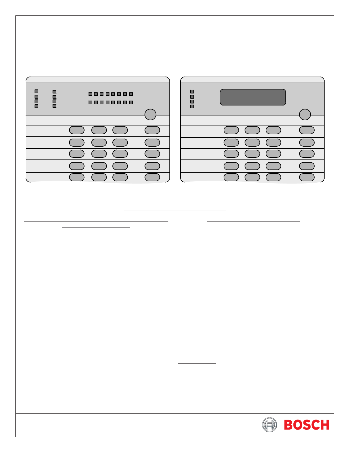
Turning On (arming) your System using the DS7445/DS7445i
or DS7447/DS7447E Keypad
Normal Arming [PIN] + [On]
Perimeter Arming, no entry delay [PIN] + [No Entry] +
[Perimeter Only]
Perimeter Arming, with entry delay [PIN] + [Perimeter Only]
Maximum Security Arming [PIN] + [No Entry] + [On]
Custom Arming [PIN] + [#] [4]
Set Delayed Arming [PIN] + [#] [9] [9] and enter
number of hours from
current time to the desired
arming time.
Extend Automatic Arming [PIN] + [OFF] during pre-
arm time
Force Arming Enter an arming
command followed by
[Bypass]
Zone Bypass [PIN] + [Bypass] followed
by the Zone number.
[PIN] +[Bypass] [*] to clear
ALL Bypasses.
Turning Off (disarming) your System
Enter your [PIN] followed by [Off]
Commands for other System Features
Chime Mode [PIN] + [#] [7]
System Walk T est [PIN] + [#] [8] [1]
Read Event History [PIN] + [#] [8] [9]
Battery Test [PIN] + [System Reset]
Communicator Test [PIN] + [#] [8] [2]
Fire Reset [PIN] + [System Reset]
Remote Program Dial-out [PIN] + [#][8] [3]
Remote Program Answer [PIN] + [#] [8] [6]
Battery/Sounder Test [PIN] + [#] [8] [5]
Error Display [PIN] + [#] [8] [7]
Error Display Reset [PIN] + [System Reset]
Fire Walk Test [PIN] + [#] [9] [1]
To Silence a Fire Trouble/Alarm [PIN] + [Off]
To Clear a Fire Trouble Display [PIN] + [System Reset]
Access Control
Enter your [Access Control PIN] followed by [Off]
Keypad Quick Reference Guide
NOTE: For additional information on operating this system, consult the DS7400Xi (Ver. 4+) User ’s Guide (P/N: 43851) and section 7
of this Reference Guide.
DS7447/DS7447E
1 23
456
789
0
*
#
On
No
Entry
System
Reset
Bypass
Only
Perimeter
Off
TEST WEEKLY
12345678
91011
12 13
14 15
16
Armed
Status
Power
Fire
Perimeter
Supervisory
Bell Silenced
Trouble
1 23
456
789
0
*
#
On
No
Entry
System
Reset
Bypass
Only
Perimeter
Off
TEST WEEKLY
Armed
Status
Power
Fire
DS7445/DS7445i

Page 2 P/N: F01U035325-01 Copyright © 2007 Bosch Security Systems, Inc. DS7400Xi (4+) Reference Guide
Table of Contents
Keypad Quick Reference Guide ........................................ 1
1.0 Specifications ............................................................. 4
1.1 Enclosure Housing ........................................................ 4
1.2 Temperature................................................................... 4
1.3 Power.............................................................................. 4
1.4 Outputs ........................................................................... 4
1.5 Zones.............................................................................. 4
1.6 Keypads.......................................................................... 4
1.7 Communicator ............................................................... 4
1.8 Partitions ........................................................................ 4
1.9 Users.............................................................................. 4
1.10 Lightning Protection ....................................................... 4
1.11 Burglar/Fire Zone Inputs ................................................ 4
1.12 Fire Signal Initiating Circuit (2-wire mode) ................... 4
1.13 Multiplex Bus Wiring Requirements .............................. 4
1.13.1 Multiplex Zone Loop Wiring ................................ 4
1.14 Option Bus Wiring Requirements ................................. 4
1.15 Max. Load Currents ........................................................ 5
1.16 Backup Battery Calculation ............................................ 5
1.17 Standby Current Load .................................................... 5
1.18 Options ........................................................................... 6
2.0 Enclosure Installation ............................................... 8
2.1 Install the Enclosure ...................................................... 8
2.2 Install the Control/Communicator ................................. 8
3.0 Control Terminal Wiring ......................................... 10
4.0 Hardware Layout Example .....................................11
5.0 System Worksheet ................................................... 12
6.0 Glossary ..................................................................... 19
6.1 General Control Programming .................................... 19
6.2 Zone Function Programming ...................................... 19
6.3 Zone Programming ...................................................... 20
6.4 Output Programming ................................................... 21
6.5 Partition Control Programming ................................... 21
6.6 Keypad Assignment Programming ............................. 22
6.7 Emergency Key Programming .................................... 22
6.8 Custom Arming Programming .................................... 22
6.9 Force Arming ................................................................ 2 2
6.10 Ground Fault Detect Programming ............................. 22
6.11 Commercial Fire Mode Programming ........................ 22
6.12 Open/Close Report Control Programming ................ 23
6.13 Report Programming ................................................... 23
6.14 Phone Number General Control Programming ......... 24
6.15 Phone Answering Programming ................................. 24
6.16 FCC Compliance Notice .............................................. 25
6.17 FCC Phone Connection Notice To Users................... 2 5
6.18 Canadian Dept. of Communications .......................... 25
6.19 For Installations in New Zealand ................................ 25
7.0 Operating Guide ...................................................... 26
7.1 Emergency Procedures ............................................... 26
7.1.1 Identifying Alarm Sounds ................................. 26
7.1.2 Silencing Alarms .............................................. 26
7.1.3 A Cautionary Note............................................ 26
7.1.4 Use Common Sense......................................... 26
7.1.5 Caution When Entering a Building ..................... 26
7.1.6 Fire Alarms...................................................... 26
7.2 Fire Reset/Fire Trouble ................................................ 26
7.2.1 Fire Reset........................................................ 26
7.2.2 Fire Trouble ..................................................... 26
7.2.3 Dirty Smoke ..................................................... 26
7.3 Emergency Keypad Alarms ......................................... 26
7.4 Fire Safety ..................................................................... 27
7.4.1 If Installed in Family Residences ....................... 27
7.4.2 Having and Practicing an Escape Plan .............. 27
7.4.3 Installation Considerations................................ 27
7.5 Personal Identification Numbers ................................ 28
7.5.1 General Information.......................................... 28
7.5.2 Programming PINs ............................................ 28
7.6 The Master Keypad ...................................................... 2 9
7.6.1 General Information.......................................... 29
7.6.2 Master Keypad Displays .................................. 29
7.6.3 Single Partition Mode ........................................ 29
7.6.4 Arming from the Master Keypad ....................... 29
7.6.5 Disarming from the Master Keypad................... 29
T o disarm all the Partitions to which you have access: ...... 29
7.7 Keypad Error Displays ................................................. 30
7.7.1 General Information.......................................... 30
7.7.2 System Faults .................................................. 30
7.7.3 Event History ................................................... 30
7.8 Testing Your System .................................................... 3 1
7.8.1 Zone (System Walk) Test ................................. 31
31
7.8.2 Battery T est s ................................................... 31
31
7.8.3 Communicator Test........................................... 31
7.8.4 Fire Walk Test .................................................. 31
8.0 How to Program the Control Panel ...................... 32
8.1 Entering the Programmer’s Mode ............................... 32
8.2 Reading Back a Program Address ............................. 32
8.3 Entering a Value in a Program Address ..................... 3 2
8.4 HEX values ................................................................... 3 2
8.5 Defaults ........................................................................ 32
8.6 Setting the Control to the Factory Default.................... 3 2
8.7 Exiting the Programmer’s Mode .................................. 32
9.0 Understanding the Programming Charts ............ 33
10.0 Programming............................................................ 34
10.1 General Control Programing:
Program Address (0000) ............................................. 34
10.2 Zone Function Programming: ..........................................
Program Addresses (0001-0030) ............................... 35
10.3 Zone Programming:
Program Addresses (0031-0278) ............................... 36
10.4 Zone Programming:
Zone Type Program Addresses (0415-0538) ............. 37
10.5 Zone Partition Assignment:
Program Addresses (0287-0410) ............................... 38
10.6 Zone Bypass Programming:
Program Addresses (2721-2724) ............................... 39
10.7 Output Programming:
Program Addresses (2734, 2735, 2736) .................... 41
10.8 Output Partition Assignment:
Program Addresses (2737-2738) ............................... 42
10.9 Partition Control Programming:
Program Address (3420) ............................................. 42
10.10 Quick Arm Control Programming:
Program Address (3477) ............................................. 43
10.11 Keypad Assignment Programming:
Program Addresses (3131-3138) ............................... 44
10.12 Keypad Partition Assignment:
Program Addresses (3139-3146) ............................... 44
10.13 Emergency Key Programming:
Program Addresses (3147-3148) ............................... 45
10.14 Custom Arming Programming:
Program Addresses (2725-2728) ............................... 45
10.15 Force Arming and Ground Fault Detect Programming:
Program Address (2732) ............................................. 47

DS7400Xi ( 4+) Reference Guide Copyright © 2007 Bosch Security Systems, Inc. P/N: F01U035325-01 Page 3
10.16 Commercial Fire Mode Programming:
Program Address (2733) ............................................. 48
10.17 Open/Close Report Control Programming:
Program Address (3149) ............................................. 49
10.18 Open/Close & Zone Report Control Programming:
Program Address (3151) ............................................. 49
10.19 Report Control Programming:
Program Address (3152) ............................................. 49
10.20 Timer Programming:
Program Addresses (4028-4030, 4032-4033) .......... 50
10.21 AC Fail Report Delay Programming:
Program Address (4034) ............................................. 50
10.22 General Authority Programming:
Program Address (3421-3424) ................................... 51
10.23 Arming Warning Programming:
Program Addresses (3425-3428) ............................... 51
10.24 DS7412 RS232 Interface Control Programming:
Program Address (4019) ............................................. 52
10.25 DS7412 RS232 Interface Configuration Programming:
Program Address (4020) ............................................. 52
10.26 RS232 Carriage Return/Line Feed Control:
Program Address (4027) ............................................. 52
10.27 Report Programming:
Program Addresses (3207-3419) ............................... 53
10.28 Phone/DS7416i Routing Control:
Program Addresses (3153-3154) ............................... 55
10.29 Account Code Programming:
Program Addresses (3429-3459) ............................... 56
10.30 Phone Number General Control Programming:
Program Address (3155) ............................................. 57
10.31 Phone Number Format Programming:
Program Addresses (3156-3157) ............................... 57
10.31.1 Compatible Receivers ...................................... 58
10.32 Phone Answering Programming:
Program Address (3158) ............................................. 58
10.33 Pager Delay Time:
Program Address (4038) ............................................. 59
10.34 Programmer’s and Master Code Programming:
Program Addresses (7589-7592) ............................... 59
10.35 PIN Length Programming:
Program Address (3478) ............................................. 59
10.36 Octal Relay Module Output Programming .................. 6 0
10.36.1 Follow Action:
Program Addresses (2740-2771)..................... 60
10.36.2 Follow System Wide Event:
Program Addresses (2740-2771)..................... 61
10.36.3 Follow Function:
Program Addresses (2740-2771)..................... 62
10.36.4 Follow Zone:
Program Addresses (2740-2771)..................... 63
10.36.5 Octal Relay Module Output Partition Assignment:
Program Addresses (2844-2851)..................... 65
10.37 Output Function Programming:
Program Addresses (2772-2843) ............................... 66
10.37.1 Output Function Partition Assignment:
Program Addresses (2852-2863)..................... 67
10.38 Dual Phone Line/Bell Supervision Module Output
Programming:
Program Address (4021) ............................................. 67
10.39 Call-Out Timer Programming:
Program Addresses (4022-4025) ............................... 68
10.40 Test Report and Remote Programmer Call-Out
Programming:
Program Address (4026) ............................................. 68
10.41 Alpha Description Programming:
Program Addresses (0545-2720, 5001-6920) .......... 69
10.41.1 Alpha Description Programming:
A Worksheet ................................................... 70
10.42 Phone Number Programming:
Program Addresses (3159, 3175, 3191) .................... 74
10.42.1 Phone Number 1 Programming:
Program Address (3159) ................................. 74
10.42.2 Phone Number 2 Programming:
Program Address (3175) ................................. 74
10.42.3 Phone Number 3 Programming:
Program Address (3191) ................................. 74
11.0 Installation Guide for UL Listed Systems ............ 75
11.1 DS7400Xi UL Listings: ................................................ 7 5
1 1.1.1 UL System Configurations................................ 75
11.2 Installation Considerations ......................................... 76
11.3 Programming the DS7400Xi ....................................... 76
1 1.3.1 Household Fire Alarm Using Digital Alarm
Communicator Transmitter With Local Bell ........ 76
11.3.2 Grade A Household Burglary Alarm Using Digital
Alarm Communicator Transmitter With Local Bell76
11.4 General System Requirements .................................. 76
11.4.1 Local Burglary Alarm ....................................... 77
11.4.2 Police Station Connection ................................. 77
11.4.3 Central Station Burglary Alarm and
Proprietary....................................................... 77
11.5 Commercial Fire Alarm ................................................ 77
11.6 Wiring and Programming Information for Installations
Using the Ademco AB-12 Bell/Housing ...................... 78
12.0 Report Programming .............................................. 79
12.1 4/2 Format .................................................................... 7 9
12.2 BFSK Format ................................................................ 8 0
12.3 Personal Dialing Format ............................................. 81
12.4 Pager Format ............................................................... 81
13.0 Report Programming - Values Sent ..................... 83
13.1 SIA Formats .................................................................. 8 3
13.2 CID Formats ................................................................. 85
14.0 Multiplex Zone Addressing Guide ........................ 86
15.0 Troubleshooting Guide ........................................... 87
15.1 Keypad Problems ........................................................ 87
15.2 Reporting Problems .................................................... 88
15.3 Zone Problems ............................................................ 88
15.4 General System Problems .......................................... 89
16.0 Program Addresses ................................................. 93
Index ................................................................................ 99

Page 4 P/N: F01U035325-01 Copyright © 2007 Bosch Security Systems, Inc. DS7400Xi (4+) Reference Guide
1.0 Specifications
1.1 Enclosure Housing
The standard enclosure is manufactured from 20 Guage (1.0 mm),
cold-rolled steel, and measures 12.5 by 14.5 by 3 inch (31.8 by
36.8 by 7.6 cm) (HxWxD). A keyed lock is included, and this enclosure
has provision for an optional tamper switch (required for
commercial burglary applications) for monitoring the door.
1.2 Storage and Operating Temperature
• Temperature: +32°F to +120°F (0°C to +49°C)
1.3 Power
NOTE: The total current output capacity for all auxiliary devices,
including keypads and smoke detectors = 1.5 A standby,
2.5 A alarm. The following ratings are maximum values.
The total combined output cannot exceed the maximum
load current.
• Input power: 18 VAC, 50 VA, 50 Hz./60 Hz.
• Auxiliary power: 12 VDC, 1.0 A max.
• UL Listed Alarm Power Output: 12 VDC, 1.75 A max.
• Auxiliary power voltage range: 12 V special application
• Optional Standby battery (P334): 12 V, 7.0 Ah - 35 Ah max.
• Control panel current draw: 175 mA, Standby
250 mA, Alarm
1.4 Outputs
• Alarm Output: 12 VDC, 1.75 A output. Can be programmed
for steady or pulsed output.
• Programmable Solid state current sink (1.0 A max.). Shorts to
Aux. negative when activated. Connect device
to Aux. power positive. Can be used for alarm,
arming state, or access control.** This output
is generally programmable.
• Programmable Solid state voltage source (500 mA max.). Can
be used for alarm, arming state, or access
control.** This output is generally
programmable. For use with such compatible
devices as the Listed DS250 with a 4-wire
base.
* = Current draw should be subtracted from either maximum
auxiliary or maximum alarm current draw.
** = Not investigated to the requirements of UL294.
1.5 Zones
• 8 on-board zones. Up to 248 total zones with expansion modules.
• Zone Response Time: 300 ms.
1.6 Keypads
• Maximum # of keypads: 15 Keypads
• Maximum wire length each: 1000 feet (305 m)
• Maximum wire length total: 6000 feet (1830 m) in system
• Wire type: 4 conductor, unshielded, #22 AWG
(0.8 mm) “Telephone quad” or #18
AWG (1.0 mm) quad wiring can be
home-run or daisy- chained.
NOTE: No more than 2 keypads (#22 AWG) or 3 keypads (#18
AWG) are recommended on any 1000 foot (305 m) run.
NOTE: Shared cable is not recommended for keypad, multiplex,
options bus, telephone, or siren wiring.
1.7 Communicator
Will report to two phone numbers with full single, double and back-
up reporting. Communicates in SIA (110 or 300 baud), 3/1, 3/1 Ext.,
3/1 with Parity, 3/1 Ext. with Parity, 4/1, 4/2, BFSK, Contact ID, and
Pager formats.
FCC Registration Number is ESVUSA-75333-AL-E
The ringer equivalence is 0.1B
Commercial Fire CSFM Listing Number is 7165-1062:113
Residential Fire CSFM Listing Number is 7167-1062:114
1.8 Partitions
The system has the capacity for 8 independent partitions. One
partition may be a common area.
1.9 Users
The DS7400Xi Ver 4+ system allows up to 200 individual users.
Each user will have his own PIN number (the 4- or 6-digit code
entered at the keypads) and his own authority level (to determine
which functions he may perform).
1.10 Lightning Protection
MOVs and spark gaps provide protection from lightning surges
and static discharges.
1.11 Burglar/Fire Zone Inputs
• Number of circuits: 8 Circuits on-board
• End-of-line resistor: 2.2 kΩ (P/N 25899, provided)
• Loop resistance tolerance: 60 ohms
1.12 Fire Signal Initiating Circuit (2-wire mode)
Fire circuit will work with 2- or 4-wire detectors and has optional
alarm verification.
• Number of circuits: 8 Circuits on-board
• Type of circuit: Class B, latching
• End-of-line resistor: 2.2 kΩ (P/N 25899, provided)
• Supervisory current: 5.5 mA
• Maximum short circuit current: 22 mA
• Maximum line resistance: 60 ohms
• Circuit voltage range: 8.5 to 14.1 VDC
• Total detector standby current: 2.5 mA
1.13 Multiplex Bus Wiring Requirements
NOTE: Do not use twisted-pair or shielded cable. Do not share
cable with the keypad lines.
• #22 AWG (0.8 mm). Up to 2000 feet (610 m) per system.
• #18 AWG (1.0 mm). Up to 5000 feet (1525 m) per system.
1.13.1 Multiplex Zone Loop Wiring
• Maximum wire length not to exceed 500 feet (150m) regardless
of the wire gauge.
1.14 Option Bus Wiring Requirements
• Maximum wire length 1000 feet (305 m) per home-run.
Output 1*
Output 2*
NOTE: Fire Systems installed under NFPA-72 or UL Listed Fire
Systems require the use of 18 AWG or larger wire.
DS7400Xi ( 4+) Reference Guide Copyright © 2007 Bosch Security Systems, Inc. P/N: F01U035325-01 Page 5
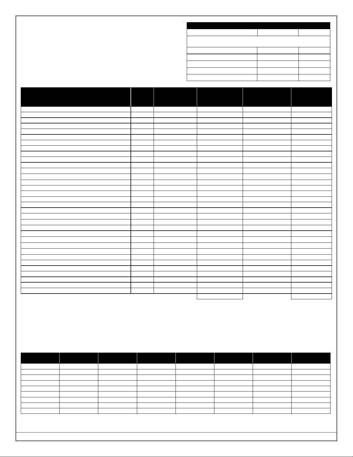
1.16 Backup Battery Calculation
• The following table is used to calculate the standby battery
capacity required by NFPA when using the DS7400Xi:
1.17 Standby Current Load
• Battery Ah - (20% Storage + 0.375 Ah Alarm)
• The following table is the derated battery divided by hours minus the control standby (175 mA):
1.15 Max. Load Currents
* = Add 15 mA for each additional zone in alarm.
** = When calculating Standby and Alarm Current for the Octal Relay Module, use 10 mA plus 40 mA for each activated relay.
*** = Maximum current draw if using the DS7400Xi Panel power supply. Total of all outputs cannot exceed 750 mA.
Rechargeable
Battery Size
Max. Standby
for 4 hours
Max. Standby
for 8 hours
Max. Standby
for 24 hours
Max. S tandby
for 48 hours
Max. Standby
for 60 hours
Max. Standby
for 72 hour s
Max. Standby
for 80 hours
7 Ah 1.0 A 470 mA X X X X X
8 Ah 1.2 A 580 mA X X X X X
14 Ah 1.5 A 1.1 A 270 mA X X X X
15 Ah 1.5 A 1.2 A 300 mA X X X X
17.2 Ah 1.5 A 1.5 A 380 mA 100 mA X X X
21 Ah 1.5 A 1.5 A 500 mA 16 0 mA 100 mA X X
28 Ah 1.5 A 1.5 A 740 mA 28 0 mA 190 mA 130 mA 100 mA
30 Ah 1.5 A 1.5 A 800 mA 31 0 mA 210 mA 150 mA 120 mA
35 Ah 1.5 A 1.5 A 970 mA 40 0 mA 280 mA 200 mA 170 mA
Device
Quantity
Standby Current
per Device
Total Standby
Current
(Quantity x Standby
Current per Devic e)
Alarm Current
per Device
Total Alarm
Current
(Quantity x Alarm
Current per Devic e)
DS7400Xi (4+) Control Panel 1 175 mA 175 mA 250 mA 250 mA
DS7416i Advanced Radio Communications Module 127 mA 127 mA
DS7412 - RS232 Serial Interface Module 35 mA max. 35 mA max.
DS7420i -Dual Phone Line/Bell Supervision Module 20 mA 140 mA
DS7430 – Multiplex Expansion Module 65 mA 65 mA
DS7432 – 8-Input Remote Module 10 mA 10 mA
DS7433 – 8-Input Direct Module 65 mA 80 mA*
DS7436 – Dual Multiplex Expansion Module 130 mA 130 mA
DS7445/DS7445i Keypad 75 mA 75 mA
DS7447/ DS7447E Keypad 100 mA 100 mA
DS7448 Keypad 80 mA 100 mA
DS7450, DS7452, DS7455 Contact Points
350
μ
A
350
μ
A
DS7457 – Single Zone Multiplex Input Module
350
μ
A
350
μ
A
DS7460 – Dual Zone Module 1 mA 1 mA
DS7465 – Input/Output Module 1 mA 1 mA
DS7480 – Bell Supervision Module 7 mA 50 mA
DS7481 – Single Phone Line Monitor 20 mA 20 mA
DS7488 – Octal Relay Module** 10 mA + 40 mA** 10 mA + 40 mA**
DS7489 – Solid State Output Module 10 mA 750 mA max.***
MX280 Series Multiplex Smoke Detectors
500
μ
A
560
μ
A
MX540 (DS7473) PIR D etector
800
μ
A
800
μ
A
MX835 TriTech
®
PIR/Microwave Detector 6 mA 35 mA
MX775 (DS7470) PIR D etector
200
μ
A
200
μ
A
MX794 (DS7474) PIR D etector
800
μ
A
800
μ
A
MX934 (DS7471) PIR D etector
200
μ
A
200
μ
A
MX938 (DS7472) PIR D etector
200
μ
A
200
μ
A
MX950 (DS7476) TriTech
®
PIR/Microwave Detector 6 mA 35 mA
RF3222 Wireless Receivers 30 mA 30 mA
2-Wire Smoke Detectors
4-Wire Smoke Detectors
Bells, Horns, etc.
Other Sensors
Other
Grand Total
Grand Total
Max. Load Currents Standby Alarm
UL Installa tions 1.5 A 2.5 A
Maximum Current By Outpu t:
Not to excee d the maximum load currents listed above in Standby or Alarm
Aux. Power & Keyp ad (Combine d) 1.0 A 1.0 A
Option Power 1.0 A 1.0 A
Bell Output X 1.75 A
Programmable Output 2 500 mA 500 mA
Loop Power + 500 mA 500 mA

Page 6 P/N: F01U035325-01 Copyright © 2007 Bosch Security Systems, Inc. DS7400Xi (4+) Reference Guide
1.18 Options
• DS7412: RS232 Serial Interface module.
The DS7412 module allows the panel to send event
information, in an ASCII format, directly to a serial
printer or computer. In addition, the interface allows
the direct connection of a computer to the panel for
programming via the WDSRP programming software.
• Current Draw= 25 mA; 35 mA with LEDs on.
• DS7416i: Advanced Radio Communications Module provides
a means of communicating alarm and supervision
signals using the Motient radio network. This can
be a replacement for, or a complement to, the
standard digital communicator.
• Current draw = 127 mA Standby and Alarm.
• DS7420i: Dual Phone Line/Bell Supervision Module (1 per
system).
The DS7420i allows the control to be used in NFPA
72 installations. It provides two supervised 12.0 VDC
signaling outputs, one Class A (Style D) input zone,
and dual phone line transmission and supervision.
• Current Draw = 20 mA Standby; 140 mA Alarm.
• DS7430: Multiplex Expansion Module (1 per system).
The DS7430 provides a two-wire multiplex bus for
the connection of additional remote zones. It also
supplies up to 200 mA for 4-wire multiplex devices
such as the DS7432.
• Current Draw = 65 mA, Standby; 65 mA, Alarm.
• DS7432: 8-Input Remote Module (up to 30 per system.
Requires a DS7430 or DS7436 Multiplex Expansion
Module).
The DS7432 provides a means of monitoring
conventional Normally Open or Normally Closed
contacts. It reports their status to the control panel
as multiplex addresses. It occupies eight multiplex
zones on the system and can monitor up to eight
separate loops. It will support 4-wire smoke
detectors.
• Current Draw = 10 mA; Standby. 10 mA, Alarm.
• DS7433: 8-Input Direct Module (1 per system. Can not be used
with the DS7430 or DS7436 Multiplex Expansion
Modules).
The DS7433 provides a means of expanding the
system to include eight additional hard-wired zones.
Each zone can support up to twenty 2-wire smoke
detectors (can also support 4-wire smoke detectors).
• Current Draw = 65 mA, Standby; 80 mA, Alarm.
Add 15 mA for each additional zone in alarm.
• DS7436: Multiplex Expansion Module. (1 per system.)
The DS7436 provides two two-wire multiplex buses
for the connection of up to 120 remote points. It
also supplies 200 mA per bus.
• Current Draw = 130 mA, Standby or Alarm.
• DS7445/DS7445i: Control Station. (15 Keypads max. per
system). The DS7445/DS7445i is an LED keypad
which has LEDs representing the first 8 zones of
the system. It displays information on various
control panel functions. A built in sounder is used
as an interior warning device and to annunciate
keystroke entries.
• Current Draw = 75 mA, Standby; 75 mA, Alarm.
• DS7447/DS7447E: Control Station. (15 Keypads max. per
system)
The DS7447/DS7447E is an Alpha-Numeric LCD
keypad. It displays information on various control
panel functions. A built-in sounder is used as an
interior warning device and to annunciate keystroke
entries.
• Current Draw = 100 mA, Standby; 100 mA, Alarm.
• Keypad Access Output: The DS7447/DS7447E
Alpha Keypad will provide a ten (10) second access
relay output if equipped with the optional K800 Relay.
The relay will energize at the keypad if the user has a
master, unlimited, general, or access PIN. The output
will change only if the user has access to the partition
assigned to the keypad. See the DS7445/DS7447
Keypad Installation Instructions (P/N: 22235) or the
DS7445/DS7445i/DS7447E Installation Instructions
(P/N: 4998138630) for wiring information.
• DS7448: Control Station. (15 Keypads max. per system)
The DS7448 is a four-wire LCD annunciator
keypad. It has a Silence key and a Reset key used
for controlling annunciator and control panel
operation, a Keylock Switch that can be used to
lock out the annunciator to prevent unwanted
silencing or resetting of the control panel, and a
two-line, 16-character Display capable of showing
all messages normally displayed on a DS7447/
DS7447E keypad.
• Current Draw = 80 mA, Standby; 100 mA, Alarm
• DS7450: Flush Mount Single Multiplex Contact Point (requires
a DS7430 Multiplex Expansion Module).
The DS7450 is intended as a replacement for
conventional dry contacts, and to report an actual
multiplex address to the control panel. Occupies 1
zone.
• Current Draw = 350 μA, Standby; 350 μA, Alarm.
• DS7452: Surface Mount Single Multiplex Contact Point (requires
a DS7430 Multiplex Expansion Module).
The DS7452 is intended as a replacement for
conventional dry contacts, and to report an actual
multiplex address to the control panel. Occupies 1
zone.
• Current Draw = 350 μA, Standby; 350 μA, Alarm.
• DS7455: Surface Mount Single Multiplex Contact Point
(requires a DS7430 Multiplex Expansion Module).
The DS7455 is intended as a replacement for
conventional dry contacts, and to report an actual
multiplex address to the control panel. Occupies 1
zone.
• Current Draw = 350 µA, Standby; 350 µA, Alarm.
• DS7457: Single Zone Multiplex Input Module (requires a
DS7430 Multiplex Expansion Module).
The DS7457 provides a means of monitoring
conventionally Normally Open or Normally Closed
contacts. It reports their status to the control panel as
multiplex addresses. It occupies one multiplex zone
on the system and can monitor one loop. It also
includes a tamper loop.
• Current Draw = 350 μA, Standby; 350 μA, Alarm.

DS7400Xi ( 4+) Reference Guide Copyright © 2007 Bosch Security Systems, Inc. P/N: F01U035325-01 Page 7
• DS7460: Dual Zone Module (up to 60 per system. Requires a
DS7430 Multiplex Expansion Module).
The DS7460 provides a means of monitoring
conventional Normally Open or Normally Closed
contacts. It reports their status to the control panel as
multiplex addresses. It occupies two multiplex zones
on the system and can monitor up to two separate
loops.
• Current Draw = 1 mA, Standby; 1 mA, Alarm.
• DS7465: Input/Output Module (up to 60 per system. Requires
a DS7430 Multiplex Expansion Module).
The DS7465 provides a Form “C” relay that may be
programmed to activate on system events, and an
input loop to monitor conventional Normally Open or
Normally Closed contacts. It reports their status to
the control panel as multiplex addresses.
• Current Draw = 1 mA Standby; 1 mA with relay
energized.
• Occupies 2 zones.
• DS7480: Bell Supervision Module (1 per system).
The DS7480 provides a means of monitoring bells. It
provides a supervised (polarity reversing) output relay
to activate the bell. It also provides a Form “C” Bell
Fault Output to be connected to the control panel.
• Current Draw = 7 mA @ 12 VDC, Standby; 50 mA
@ 12 VDC, Alarm.
• DS7481: Single Phone Line Monitor (1 per system).
The DS7481 provides a means of monitoring a single
phone line for fault conditions. When a fault is
detected, the DS7481 automatically closes its
Normally Open relay contacts to provide a means of
signaling the fault.
• Current Draw = 20 mA, Standby; 20 mA, Alarm.
• DS7488: Octal Relay Module (2 per system).
The DS7488 provides 8 Form “C” relay outputs for
addition to the system. The outputs are fully
programmable and can be activated by system
events. Each output operates individually of the other
7 outputs for complete flexibility.
• Current Draw = 10 mA + 40 mA for each relay
when energized.
• DS7489: Solid State Output Module (2 per system).
The DS7489 is a Solid State Octal Driver Module that
provides 8 open collector transistor outputs. The
outputs are fully programmable and can be activated
by system events. Each output operates individually
of the other 7 outputs for complete flexibility. The
DS7489 Module has not been investigated by
Underwriters Laboratories, Inc.
• Current Draw = 10mA.
• Outputs: Provides a current sink (the output shorts
to common (-) when activated). The maximum
current draw for all 8 outputs combined cannot
exceed 750 mA.
• DS9484: The DS9484 is a Remote Notification Appliance
Circuit (NAC) Power Supply designed to add four
additional NACs (NFPA 72 Class B, Style Y) to a
Fire Alarm Control Panel (FACP). When connected
to the Options Bus of the DS7400Xi, it can provide
intelligent control of its individual outputs. It
supplies 6 A of NAC power through four circuits to
drive horn strobe loads. It is UL Listed as a fire
accessory for use in Commercial fire applications
and as a continuous-load power supply for auxiliary
devices.
• Current Draw = 150 mA, Standby; 6 A maximum,
Alarm
• MX280: Multiplexed Photoelectric Smoke Detector (up to 120
detectors may be used per system. Requires a
DS7430 and occupies one multiplex zone). Detects
smoke and automatically determines the detector’s
sensitivity using the Detection Systems “Chamber
Check” feature.
• Current Draw = 500 μA, Standby; 560 μA, Alarm.
• MX280TH: Multiplexed Photoelectric Smoke Detector with a
135°F heat sensor (up to 120 detectors may be used
per system. Requires a DS7430 and occupies one
multiplex zone). Detects smoke and is equiped with
a 135°F heat sensor for high temperature alarms.
The Detection Systems “Chamber Check” feature
automatically determines the detector’s sensitivity.
• Current Draw = 500 μA, Standby; 560 μA, Alarm.
• MX280THL: Multiplexed Photoelectric Smoke Detector with a
135°F heat sensor and a 45°F freeze alarm (up to 60
detectors may be used per system. Requires a
DS7430 and occupies two multiplex zones). Detects
smoke and is equiped with a 135°F heat sensor for
high temperature alarms and a 45°F sensor for freeze
alarms. Freeze alarms are reported separately from
smoke and high temperature alarms. The Detection
Systems “Chamber Check” feature automatically
determines the detector’s sensitivity.
• Current Draw = 500 μA, Standby; 560 μA, Alarm.
• MX540: Multiplexed Passive Infrared (PIR) Intrusion Detector
(DS7473) with a standard range of 40 by 50 feet (12
by 15 meters). Requires a DS7430 and occupies
one multiplex zone.
• Current Draw = 200 μA, Standby; 2 mA, Alarm.
• MX835 TriTech Microwave/PIR Intrusion Detector with “Pet
Avoidance” technology and a standard range of 35 by
35 feet (10.7m by 10.7 m). Requires a DS7430 and
occupies one multiplex zone.
• Current Draw = 6 mA, Standby; 35 mA in “Trouble”
and Walk Test mode.
• MX775 Multiplex Passive Infrared (PIR) Intrusion Detector with
(DS7470) a standard range of 50 by 50 feet (15 m by
15 m). Requires a DS7430 and occupies one multiplex
zone.
• Current Draw = 200 μA, Standby; 2 mA in Walk
Test mode.
Page 8 P/N: F01U035325-01 Copyright © 2007 Bosch Security Systems, Inc. DS7400Xi (4+) Reference Guide
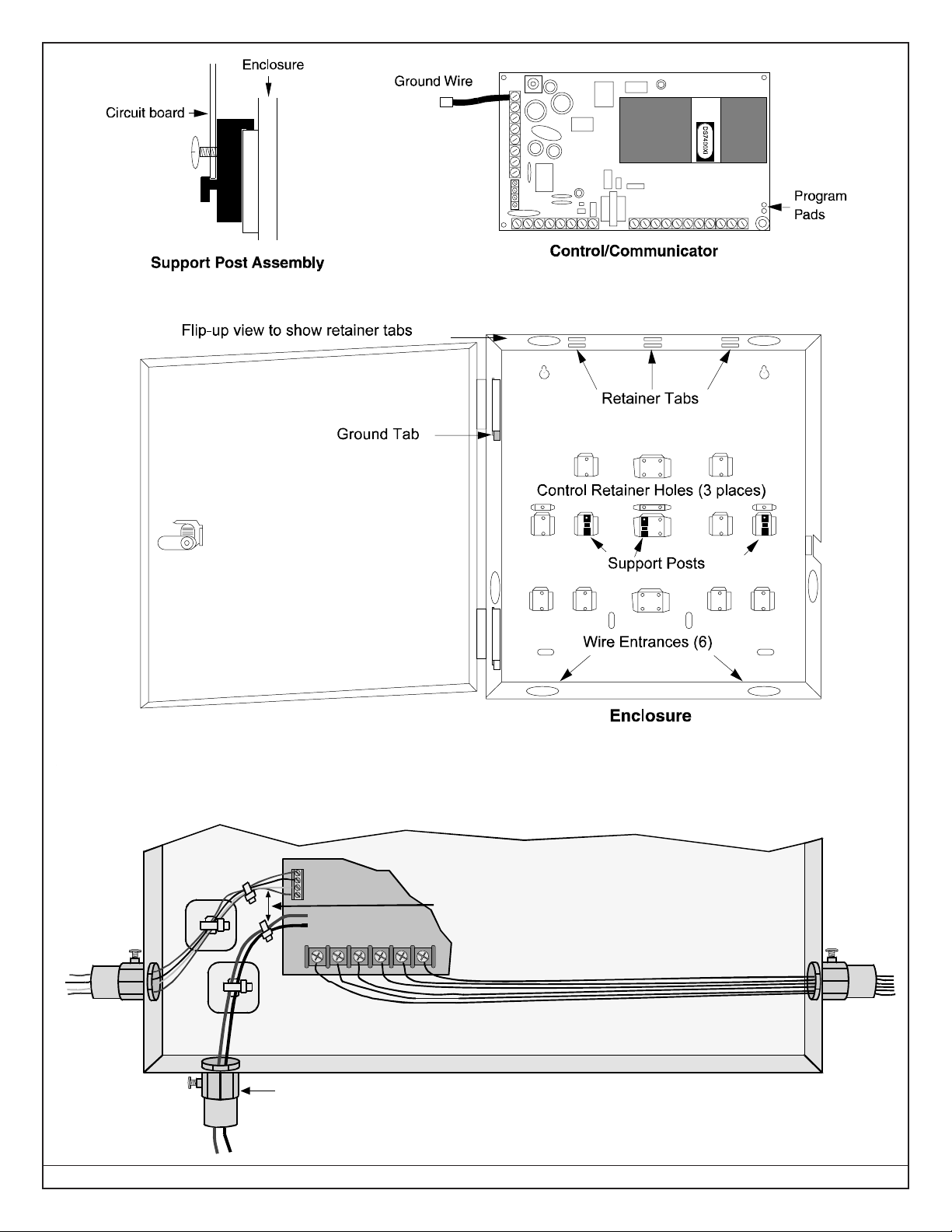
2.0 Enclosure Installation
The DS7400Xi control/communicator and the enclosure are
shipped together. The control, however, still needs to be installed
into the enclosure. Hardware for mounting the enclosure to a wall,
and the control to the enclosure is located in its own hardware
pack.
2.1 Install the Enclosure
• Use the enclosure as a template and mark the top mounting
holes on the mounting surface.
• Pre-start the mounting screws for these two holes. Slide the
enclosure onto these mounting screws so that the screws move
up into the thinner section of the holes. Tighten the screws.
• Screw in the remaining two screws in either set of bottom
mounting holes.
• Knock out the desired wire entrances on the enclosure.
2.2 Install the Control/Communicator
The control is static sensitive. Make sure you touch
earth ground before handling the control. This will
discharge any static electricity in your body. Example:
Run the ground wire to the enclosure before handling
the control. Then keep holding the ground wire while
installing the control.
• Insert the three support posts into the control retainer holes as
shown in the diagram.
• Slide the top of the control into the retainer tabs (the slots under
the top frame).
• Once in the retainer tabs, the control will rest on the three support
posts.
• Secure the bottom of the enclosure by screwing the bottom three
holes through the support posts and through to the control
retainer holes.
Once the control is installed, be sure to connect its
ground wire to the top hinge of the enclosure (the
unpainted tab).
• MX794 The MX794 is a Long Range Multiplex PIR intrusion
(DS7474) Detector with Self-test. The standard ranges
are 80 ft. by 50 ft. (24.0 m by 15.0 m) and 200 ft. by 10 ft.
(61.0 m by 3.1 m). Requires a DS7430 and occupies
one multiplex zone.
• Current Draw = 800 μA, Standby; 2 mA, Alarm.
• MX934 Multiplex Passive Infrared (PIR) intrusion detector with
(DS7471) a standard range of 35 by 35 feet (10.7 m by
10.7 m). Requires a DS7430 and occupies one multiplex
zone.
• Current Draw = 200 μA, Standby; 2 mA in Walk
Test mode.
• MX938 360° Ceiling Mount Multiplex PIR Intrusion Detector
(DS7472) with a 60 foot (18.3 m) diameter range.
Requires a DS7430 and occupies one multiplex zone.
• Current Draw = 200 μA, Standby; 2.5 mA in Walk
Test mode.
• MX950 Multiplex TriTech Microwave/PIR Intrusion Detector
(DS7476) with motion monitor and antimask features
and with a standard range of 50 by 50 feet (15 m by
15 m). Requires a DS7430 and occupies one multi-
plex zone.
• Current Draw = 6 mA, Standby; 35 mA in “Trouble”
and Walk Test mode.
• RF3222: 120-zone Wireless Receiver. (up to two receivers
per system. Requires use of a DS7430 or DS7436
Multiplex Expansion Module.)
See the DS7400Xi (4+) Wireless Reference Guide
(P/N: 44575) for more information.
• Current Draw = 30 mA
The control/communicator is also available in three package for-
mats. The packages include the following:
• DS7400XiF: DS7400Xi in large red enclosure manufactured
from 18 Guage (1.2 mm), cold-rolled steel,
measuring 15.0 by 20.75 by 4.25 inch (38.1 by 52.7
by 10.8 cm) (HxWxD).
• DS7400XiFCP: DS7400XiF package with: DS7420i, DS7447/
DS7447E and a AE-TR16
• DS7400XiCC: DS7400Xi in an Attack Enclosure.
When installing a UL Listed system, refer to Section 1 1.0, Installation
Guide for UL Listed Systems.
DS7400Xi ( 4+) Reference Guide Copyright © 2007 Bosch Security Systems, Inc. P/N: F01U035325-01 Page 9
T
he Battery Terminals and Wires are NOT Power Lim ited.
A ¼ in. (6.4 m m) spacing must be maintained between
t
he battery terminals, battery wiring and all other wiring. Battery wirin g m ay not share the same conduit, conduit
f
ittings or conduit knock-outs with other wiring.
¼ in. (6.4 mm) Minimum
Option or
Keypad Wires
Output or
Zone Wires
Battery Wir es
Only required if
external batteries
are used
To ensure proper spacing
secure wires using
Tie-Wraps or similar device s
Wiring
Page 10 P/N: F01U035325-01 Copyright © 2007 Bosch Security Systems, Inc. DS7400Xi (4+) Reference Guide
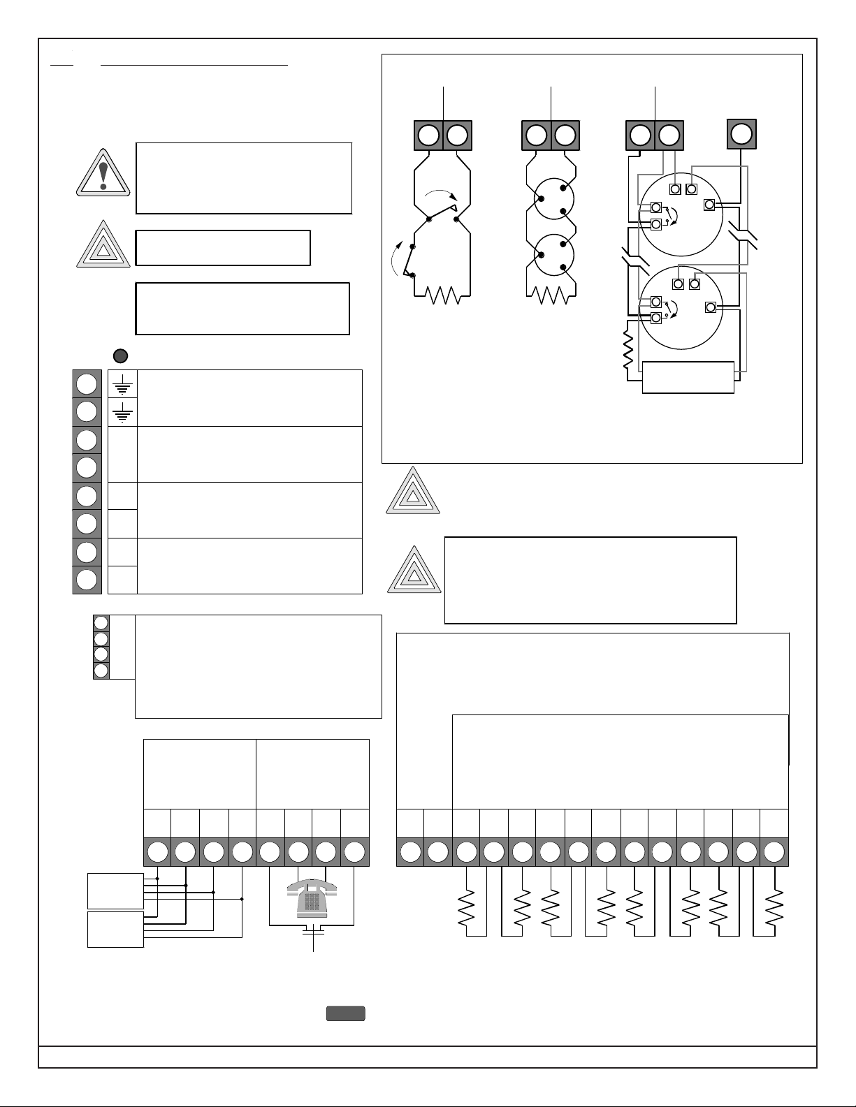
3.0 Control Terminal Wiring
NO
Typical burglar
alarm loop wiring
Z– L+
Typical 2-wire
smoke detector
wiring
Z– L+
Alarm
Power
++
–
Loop +
or PO2
Zone
Input
Aux. Power (—)
(terminal 5 or 7)
–
Alarm
Power
++
–
Typical 4-wire smoke
detector wiring.
For example:
Detection Systems’
DS250 in an MB4W base.
End-of-Line
Super v is io n Re la y
(e.g. Detec tio n Sys tems’
EOL200)
Z– L+
Loop +Zone
Input
Loop +Zone
Input
in out
in out
NC
TYPICAL BURGLAR AND FIRE WIRING
(for a list of
compatible 2-wire
smoke detectors,
see Technical Service
Note P/N 27685)
EARTH GROUND:
Must be connected to
a good earth ground such as a cold water
pipe and also connected to the cabinet cover,
using the supplied wire jumper.
ALARM O UTPUT:
Provides 12 VDC, spec ial application, up to
1.75 A for powering bells, siren drivers, etc.
Function programmed in address 2734.
A/C INPUT: Use U. L. listed, 18 VAC 50
VA, class 2 transformer. Model TR-1850
requires 50/60 Hz. unswitched dedicated
outlet - do not share.
1
2
3
4
5
6
7
8
A
C
–
A
–
+
AUXILIARY POWER:
Provides 12 VDC, spec ial application, up to
1.0 A for powering detectors.
A/C Power Indica tion LED
OPTION BUS:
Used for options such as the DS7416i
Communications Module, the DS7420i Dual
Phone Line Module, etc.
Also for keypads #11 - #15.
For Commercial Fire Mode: Option Bus wiring
should be in conduit if run ouside the
enclosure.
O
P
T
I
O
N
R
B
G
Y
Shared cable is not recommended for keypad,
multiplex, options bus, telephone, or siren wiring.
ZONES 1-8: Zones 1-8 are intended for connection of Normally
Open or Normally Closed alarm contacts. They may also be used
for compatible 2-wire smoke detectors. These zones require a
2.21k
Ω
resistor (P/N 25899) at the end of the loop. Power is
momentarily removed from L+ after a [PIN] + [System Reset] or
during a fire verification.
Zone 1-8 assignments are programmed in address 0031-0038.
17 18 19 20 21 22 23 24 25 26 27 28 29 30
PO1 PO2
1–
L+
2– 3– 5– 6– 7– 8–4–
L+ L+ L+
PROGRAMMABLE OUTPUTS:
PO1 shorts to aux. power negative when activ ated, PO1 can sink up to 1.0 A.
PO1 function programmed in address 2735.
PO2 supplies 12 V and up to 500 mA when activated.
PO2 function programmed in address 2736.
KEYPAD BUS*:
Up to 15 keypads**
may be used. Can be
“home-run” or
“daisy-chained.”
9 10 1 12 13 14 15 16
RBGYGBSR
Keypad
(#1 - #10)
PHONE LIN E:
* = Maximum wire length each: 1000 ft. (305 m).
Maximum wire length total in system: 6000 ft. (1830 m) when using
#22 AWG (0.8 mm) or #18 AWG (1.0 mm) cable.
** = Keypads #1 - #10 connect to the Keypad Bus and keypads #11 - #15
connect to the Option Bus.
TTHRHR
Keypad
(#1 - #10)
An appropriate two pole disconnect device must be installed
by qualified service personnel, as part of the building installation.
Before servicing, remove all power
including the transformer, battery and
phone line. A complete functional test
is required after any programming.
WARNING
System is Power Limited except for
battery t erm inals. All wiring entering
this enclosure must be power limited.
Incorrect connections may
result in damage to the unit.
CAUTION
Danger of explosion if battery is incorrectly replaced.
Replace with the same or equivalent type
recommended by th e manufacturer.
Dispose of used batteries according to the
manufacturer's instructions.
CAUTION
CAUTION
NOTE
DS7400Xi ( 4+) Reference Guide Copyright © 2007 Bosch Security Systems, Inc. P/N: F01U035325-01 Page 11
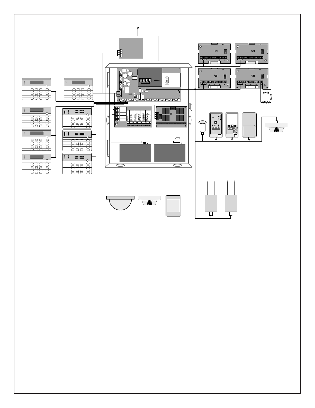
4.0 Hardware Layout Example
Armed
Statu s
Power
Fire
1 23
456
789
0
*
#
On
No
Entry
System
Rese t
Bypass
Only
Perimeter
Off
Perim eter
Supervis ory
Bell Silenced
Trouble
123456 78
®
DS7488 Octal
Relay Board
DS7400Xi
+–+–
Power Bus
DS7420i Dual Phone
Line/Be ll Supervision
Module
DS7447/DS7447E and DS7445/DS7445i
Keypads
R
DS7450/ 52 Se ri es Co nt act s , DS74 60 In pu t Mod ule
s,
DS7465 Input/Output Modules, MX540, MX775,
MX794, MX835, MX934, MX938, and MX950 mo tio
n
detectors and MX280 Series Smoke Detectors
DS7430
Keypads #11 - #15 must be connected to
the Options Bus. Keypads #1 - #10 must
be connected to the Keypad Bus .
Note :
Ensure at least 1/4" separation
between battery wires and all
other cabling.
Armed
Statu s
Power
Fire
1 23
456
789
0
*
#
On
No
Entry
System
Reset
Bypass
Only
Perimeter
Off
Armed
Status
Power
Fire
1 23
456
789
0
*
#
On
No
Entry
Syst em
Reset
Bypas s
Only
Perim eter
Off
Armed
Statu s
Power
Fire
1 23
456
789
0
*
#
On
No
Entry
System
Reset
Bypass
Only
Perimeter
Off
Armed
Statu s
Power
Fire
1 23
456
789
0
*
#
On
No
Entry
System
Reset
Bypass
Only
Perimeter
Off
Armed
Statu s
Power
Fire
1 23
456
789
0
*
#
On
No
Entry
System
Reset
Bypass
Only
Perimeter
Off
Armed
Statu s
Power
Fire
1 23
456
789
0
*
#
On
No
Entry
System
Rese t
Bypass
Only
Perimeter
Off
Perim eter
Supervis ory
Bell Silenced
Trouble
123456 78
®
Armed
Statu s
Power
Fire
1 23
456
789
0
*
#
On
No
Entry
System
Rese t
Bypass
Only
Perimeter
Off
Perim eter
Supervis ory
Bell Silenced
Trouble
123456 78
®
B
G
Y
–+––
–
–
Option
Bus
Battery
Bell Output
Auxiliary
Output
+
–
++
+
–
+
–
G
R
B
1
2
3
4
5
6
7
8
9
10
Y
1 121 314 1516 1718 1920 2122 2324 2526 2728
Battery Battery
RF3222 120-Zone
Wireless Receivers
Wireless Senso rs
RTRT TTRR TRTR
DS7432 8-Input
Remote Modules
47kΩ
Dry contact inputs
+
–
+
–
12345678
POWER BUS
+
–
+
–
1234567 8
POWER BUS
+
–
+
–
12345678
POWER BUS
+–+–
1234567 8
POWER BUS
1234
5
2G
1
-
+
BUS
NO
+
1
2
3
C
NC
DS7416i
Communications
Module
EOL
• Up to 15 keypads may be used. Keypads #1 - #10 connect to the Keypad Bus and keypads #11 - #15
connect to the Option Bus. One keypad must be designated as keypad #1 and connect ed to the Keyp ad
Bus. See th e DS7447/DS7447E, D S7445/DS7445i, and D S7448 Installati on I nstructions for f ur t her details.
• A DS7420i (Dual Phone Line/Bell Supervision Module) may be connected to the Control Panel, and
placed within the enclosure. Connect to the Options Bus of the control panel. See the DS7420i Installation
Instructions for further details.
• A DS7430 or a DS7436 (Multiplex Expansion Module) may be connected to the control panel via the
expansion port. This will allow for th e connection of additional zones via the Options Bus. See t he D S7430
or DS7436 Installation Instructions fo r furthe r details.
• Up to 2 DS7488s (Octal Relay Modules) may be connected to the Control Panel, and placed within the
enclosure. Connect to the Options Bus of the Control Panel. This provides an additional 8 Form “C”
relay outputs for the Control Panel. See the DS7488 Installation Instruct ions for further detai ls .
• A DS7416i Advanced Radio Co mmunications Module may be connected to the Control Panel via the Options
Bus. This allows for connection to a radio network.
• Up to 248 zones are available for the connecti on of Sing le, Multiple , Input/ Ou tput, and Multiplex devices.
Up to 112 wireless zones (137-248) are also available.
• Up to 2 RF3222 (120-Zone Wireless Receivers) may be connected to the DS7430 or DS7436. Connect to
the Power and Bus terminals of the Multiplex Expansion Module. This allows for the monitoring of wireless
detectors.
• Up to 30 DS74 32s (8-Input Remote Modules) may be connected to the DS 7430 or DS7436. Connect to the
Power and Bus Terminals of the Multiplex Expansion Module. This allows for a means of addressing up to
240 input loops of conventional contacts t o the Control Panel. See the DS7432 Instal lat ion Instruct ion s for
further details.
1 23
456
789
0
*
#
On
No
Entry
Syst e m
Reset
Bypass
Only
Perim eter
Off
TEST WEEKLY
1234567 8
910111213
14 1516
Armed
Status
Power
Fire
Peri meter
Supervisory
Bell Silenced
Trouble
1 23
456
789
0
*
#
On
No
Entry
Syst e m
Reset
Bypass
Only
Perim eter
Off
TEST WEEKLY
1234567 8
910111213141516
Armed
Status
Power
Fire
Peri meter
Supervisory
Bell Silenced
Trouble
1 23
456
789
0
*
#
On
No
Entry
Syst e m
Reset
Bypass
Only
Perim eter
Off
TEST WEEKLY
1234567 8
91011
12 1314 15 16
Armed
Status
Power
Fire
Peri meter
Supervisory
Bell Silenced
Trouble
Page 12 P/N: F01U035325-01 Copyright © 2007 Bosch Security Systems, Inc. DS7400Xi (4+) Reference Guide
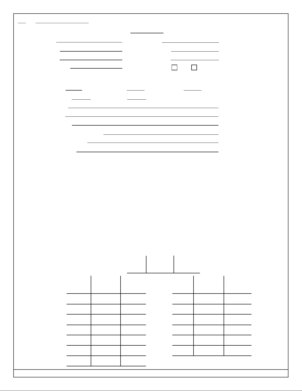
5.0 System Worksheet
A
c
c
o
u
n
t
N
u
m
b
e
r
I
n
f
o
r
m
a
t
i
o
n
Name Contact Person
Address Voice Phone Number
Panel Phone Number
City, State, Zip Panel Answers P hone Armed Disarmed
Equipment Locati on and Notes
AC Voltage VAC Battery Voltage VDC AUX Current A
Battery Standby Ah Bell Current A
Control Panel
Transformer
Telephone Jack
Telephone On Same Line as P a nel
Earth Ground Co nne ct ion
Alarm Sounder (s)
Misc . Notes
____________________________________________________________________________________
____________________________________________________________________________________
____________________________________________________________________________________
____________________________________________________________________________________
____________________________________________________________________________________
____________________________________________________________________________________
____________________________________________________________________________________
____________________________________________________________________________________
Keypad Location and Notes
Example
Location Belongs Master/
to Partition Standard
Keypad # 1 Kitchen 2 Master
Location Belongs Master/ Location Belongs Master/
to Partition Standard to Partition Standard
Keypad # 1 Keypad # 9
Keypad # 2 Keypad # 10
Keypad # 3 Keypad # 11
Keypad # 4 Keypad # 12
Keypad # 5 Keypad # 13
Keypad # 6 Keypad # 14
Keypad # 7 Keypad # 15
Keypad # 8

DS7400Xi ( 4+) Reference Guide Copyright © 2007 Bosch Security Systems, Inc. P/N: F01U035325-01 Page 13
5.0 System Worksheet (continued)
P
e
r
s
o
n
a
l
I
d
e
n
t
i
f
i
c
a
t
i
o
n
N
u
m
b
e
r
I
n
f
o
r
m
a
t
i
o
n
PIN Information
Us e r Pin # A u th . P a rti- Na me
#
Level tions
Example
002 1001 6 1, 2, 4 James L.
001
002
003
004
005
006
007
008
009
010
011
012
013
014
015
016
017
018
019
020
021
022
023
024
025
026
027
028
029
030
PIN Information
User Pin # Auth. Parti- Name
#
Level tions
PIN Info r m a tion
User Pin # Auth. Parti- Name
#
Level tions
PIN Information
User Pin # Auth. Parti- Name
#
Level tions
031
032
033
071
072
073
074
075
076
077
078
079
080
081
082
083
084
085
086
087
088
089
090
091
092
093
094
095
096
097
098
099
067
068
069
070
036
037
038
039
040
041
042
043
044
045
046
047
048
049
050
051
052
053
054
055
056
057
058
059
060
061
062
063
064
065
066
034
035
PIN Worksheet

Page 14 P/N: F01U035325-01 Copyright © 2007 Bosch Security Systems, Inc. DS7400Xi (4+) Reference Guide
5.0 System Worksheet (continued)
P
e
r
s
o
n
a
l
I
d
e
n
t
i
f
i
c
a
t
i
o
n
N
u
m
b
e
r
I
n
f
o
r
m
a
t
i
o
n
100
101
102
103
104
105
106
107
108
109
111
112
113
114
115
116
117
118
119
120
121
122
123
124
125
126
127
128
129
PIN Information
User Pin # Auth. Parti- Name
#
Level tions
PIN Information
User Pin # Auth. Parti- Nam
e
#
Level tions
PIN Information
User Pin # Auth. Parti- Name
#
Level tions
130
131
132
172
173
174
175
176
177
178
179
180
181
182
183
184
185
186
187
188
189
190
191
192
193
194
195
196
197
198
199
200
168
169
170
171
136
137
138
139
140
156
157
158
159
160
161
162
163
164
165
166
134
135
133 167
110
141
142
143
144
145
146
147
148
149
150
151
152
153
154
155
PIN Worksheet

DS7400Xi ( 4+) Reference Guide Copyright © 2007 Bosch Security Systems, Inc. P/N: F01U035325-01 Page 15
5.0 System Worksheet (continued)
Example
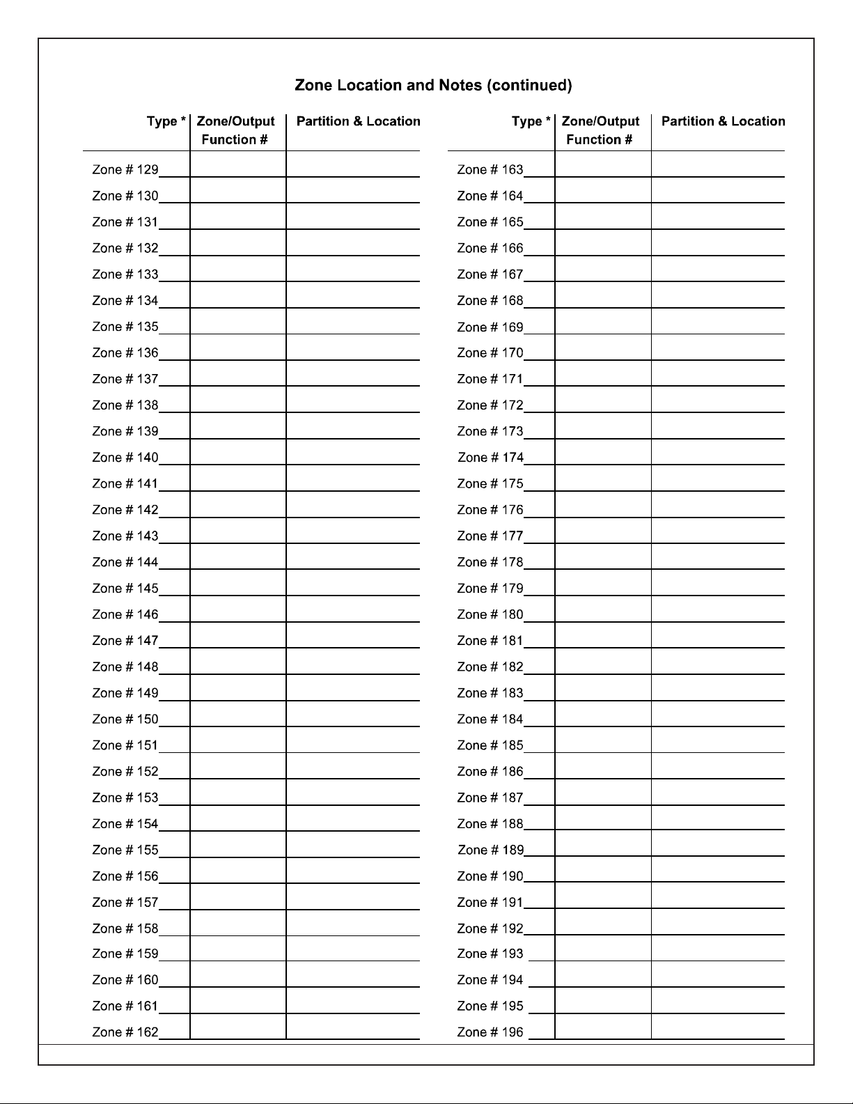
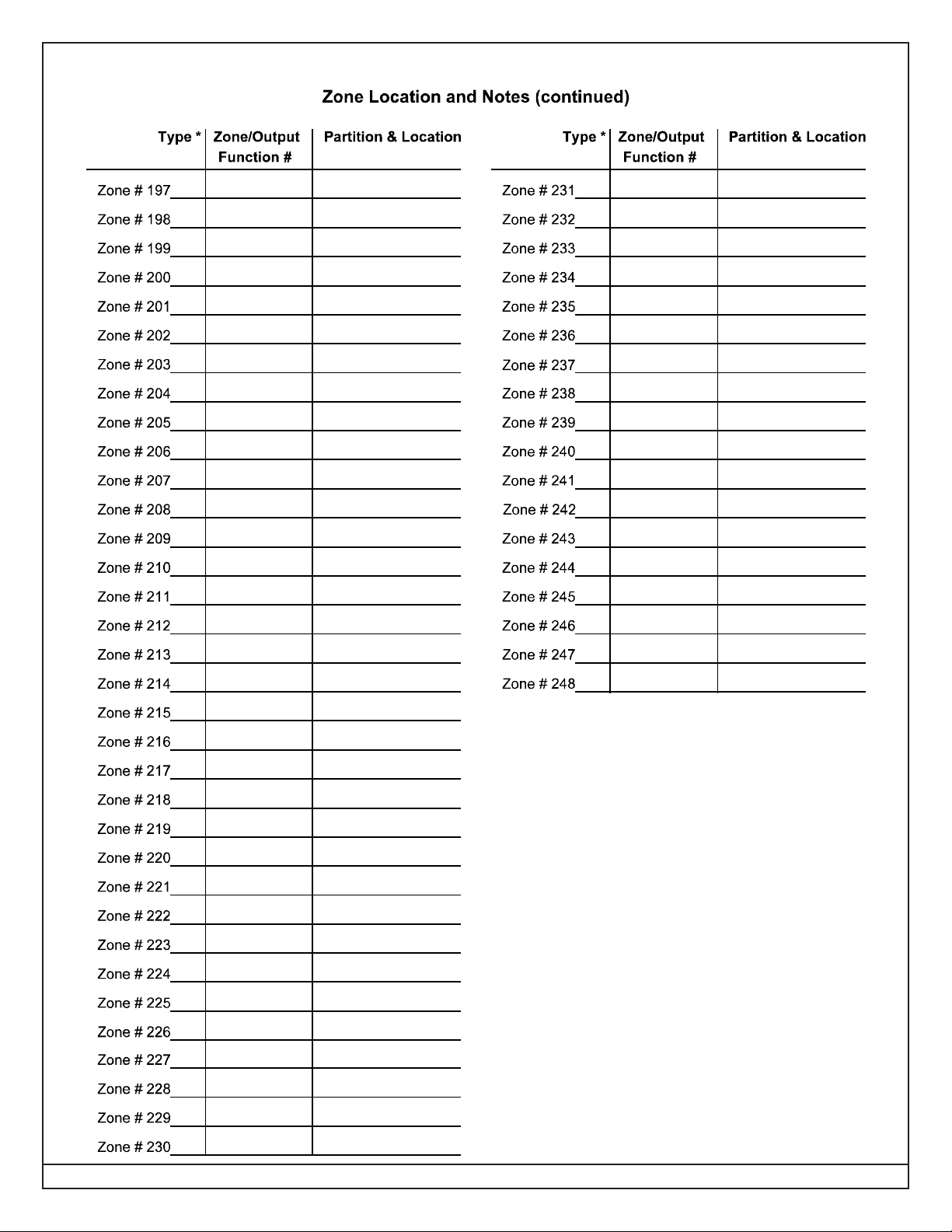
Type * Zone/Output Partition & Location
Function #
Zone # 1
Zone Location and Notes
Zn Funct. 1
Type * Zone/Outpu t Partition & Location
Function #
Zone # 1
Zone # 2
Zone # 3
Zone # 4
Zone # 5
Zone # 6
Zone # 7
Zone # 8
Zone # 9
Zone # 10
Type * Zone/Output Partition & Locatio
n
Function #
Zone # 31
Zone # 32
Zone # 33
Zone # 34
Zone # 35
Zone # 36
Zone # 37
Zone # 38
Zone # 39
Zone # 40
2, KitchenSZ
* = SZ: Single Zone Input
MZ: Multiple Zone Input
IO: DS7465
(see section 10.3)
Zone # 41
Zone # 42
Zone # 43
Zone # 44
Zone # 45
Zone # 46
Zone # 47
Zone # 48
Zone # 49
Zone # 50
Zone # 51
Zone # 52
Zone # 53
Zone # 54
Zone # 55
Zone # 56
Zone # 57
Zone # 58
Zone # 59
Zone # 60
Zone # 11
Zone # 12
Zone # 13
Zone # 14
Zone # 15
Zone # 16
Zone # 17
Zone # 18
Zone # 19
Zone # 20
Zone # 21
Zone # 22
Zone # 23
Zone # 24
Zone # 25
Zone # 26
Zone # 27
Zone # 28
Zone # 29
Zone # 30
Zone Location and Notes Worksheet
Page 16 P/N: F01U035325-01 Copyright © 2007 Bosch Security Systems, Inc. DS7400Xi (4+) Reference Guide
5.0 System Worksheet (continued)
DS7400Xi ( 4+) Reference Guide Copyright © 2007 Bosch Security Systems, Inc. P/N: F01U035325-01 Page 17
5.0 System Worksheet (continued)
Page 18 P/N: F01U035325-01 Copyright © 2007 Bosch Security Systems, Inc. DS7400Xi (4+) Reference Guide
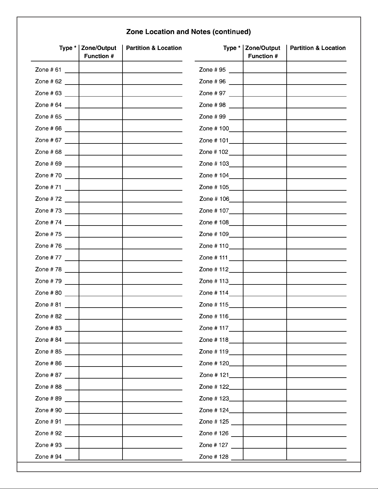
5.0 System Worksheet (continued)
Zone Location and Notes Worksheet

DS7400Xi ( 4+) Reference Guide Copyright © 2007 Bosch Security Systems, Inc. P/N: F01U035325-01 Page 19
6.0 Glossary
6.1 General Control Programming
• Normal Arming - [PIN] + [On]: If programmed, arms the entire
system while allowing entry delays for entry/exit zones.
• Perimeter Instant Arming - [PIN] + [No Entry] [Perimeter Only]: If
programmed, arms only the perimeter of the system and does
not allow entry delays for entry/exit zones.
• Perimeter Arming - [PIN] + [Perimeter Only]: If programmed,
arms only the perimeter of the system while allowing entry delays
for entry/exit zones.
• Custom Arming - [PIN] + [#] [4]: If programmed, allows custom
arming of the system and bypasses the zone functions specified
in data addresses 2725-2728.
• Maximum Security Arming - [PIN] + [No Entry] [On]: If
programmed, arms the entire system and does not allow an
entry delay for entry/exit zones.
• General Authority by Partition
A general (level 2) authority can be programmed to have arm-
only authority; arm and bypass authority; arm and disarm
authority; or arm, disarm, and bypass authority by partition. This
is done at addresses 3421-3424.
- Arm-only access by partition allows someone with a General
Authority to arm zones in a partition he can not disarm.
- This level can still be used to arm, disarm, and bypass zones
in the other partitions that it has access to.
• Closing Ring-Back: If programmed, the keypad sounders and
Bell will activate for 2 seconds after the system is armed and the
closing report is successfully sent. This requires Closing Ring-
Back and Closing Report to be programmed.
- If a closing report is not programmed, the control will test for a
dial tone when the system is armed. If the test passes, the
system will arm normally. If the test fails, the system will arm,
but will indicate a trouble condition.
- The DS7447/DS7447E keypad will display “Communication
Err” after [#] [8] [7] is entered.
• Siren on Comm. Fail for Silent Zone: If programmed, a silent
zone will sound the alarm outputs if the zone is in an alarm
condition and the system fails to communicate with the central
station.
• Restore when Sounders Silence: If programmed, a zone sends
a restoral report and is ready to activate again only after the
burglary bell cut-off time expires or the bells are silenced.
- The zone can alarm multiple times per armed period.
• Restore when Zone Restores: If programmed, a zone sends a
restoral report and is ready to activate again as soon as it
physically restores.
- This zone can alarm multiple times per armed period.
• Restore when System Disarms: If programmed, a zone sends
a restoral report when the system is disarmed.
- It can only alarm once per armed period.
• Allow Swinger Shunts: If programmed, a zone can only alarm
or trouble up to three times per armed period. After the third
alarm or trouble, the zone will be bypassed and a bypass report
will be sent.
NOTE: Swinger Shunts are not allowed on UL Certificated
Installations.
6.2 Zone Function Programming
• Zone Function
A Zone Function is the description of how a particular zone will
behave (e.g. steady alarm output, bypassing allowed, alarm on
short, trouble on open, perimeter instant).
- There are many possible zone functions. Up to 30 different
zone functions are allowed per control.
- Zone functions may be custom made as needed.
- Each zone must be programmed as a specific zone function.
Any number and combination of zones may be programmed
as particular zone functions.
- Program zone functions at addresses 0001-0030.
• Invisible Alarms : This is a zone programmed not to have an
alarm output or an alarm display at any keypad when activated.
An alarm signal will be sent, but the DS7447/DS7447E keypad
display will read “Not Ready” while this zone is violated.
- Invisible Alarm zones are recommended for holdup alarms.
• Silent Alarms: This is a zone programmed to activate the visual
display at the keypad, but not audible signals.
- If this zone is also an entry zone, an entry tone will sound when
this zone is activated.
• Bypassing Allowed: This is a zone programmed to allow
bypassing (shunting). This is done using the bypass command
or the force-arming sequence.
• Alarm on Short: This is a zone programmed to activate an
alarm when its loop is shorted.
• Alarm on Open : This is a zone programmed to activate an
alarm when its loop is opened.
• Trouble on Open: This is a zone programmed to activate a
trouble when its loop is opened and the system is disarmed.
- If the system is armed, this zone will activate an alarm if shorted
or opened.
- For 24-hour zones, regardless of the arming state of the panel,
this always remains as a Trouble on Open.
• Trouble on Short: This is a zone programmed to activate a
trouble when its loop is shorted and the system is disarmed.
- If the system is armed, this zone will activate an alarm if shorted
or opened.
- For 24-hour zones, regardless of the arming state of the panel,
this always remains as a Trouble on Short.
• Interior Delayed : This is a zone programmed to be ignored
during the entry/exit delay period. If it is violated when the system
is armed, it will activate a delay for the programmed entry delay
time. The keypad pre-alert sounders will activate and the system
may be disarmed during this delay period. If the system is not
disarmed during this delay period, this zone will activate an alarm.
This zone is bypassed by Perimeter Instant or Perimeter Armed.
• Perimeter Instant : This is a zone programmed to activate an
alarm even during the entry/exit delay period.
• 24-Hour: This is a zone programmed to activate when its loop is
faulted, even if the system is disarmed.
• Entry/Exit Delay #1: This is a zone programmed to be ignored
during the entry/exit delay period.
- If it is violated while the system is armed, it will activate a delay
for the amount of time programmed for entry delay time #1
(address 4028). The keypad pre-alert sounders will activate
and the system may be disarmed during this delay period.
- If the system is not disarmed during the entry period, this zone
will activate an alarm.

Page 20 P/N: F01U035325-01 Copyright © 2007 Bosch Security Systems, Inc. DS7400Xi (4+) Reference Guide
• Entry/Exit Delay #2: This is a zone programmed to behave
identical to the Entry/Exit Delay #1 zone function except that it
uses entry delay time #2 (address 4029).
NOTE: If both entry delays have been activated, the control will
use the shorter entry delay.
• Entry/Exit Delay Cancel Zone Functions
Entry/Exit Delay Cancel 1 and Entry/Exit Delay Cancel 2 Zone
Functions cause the exit delay to expire as soon as the premises
is vacated.
- If a zone is programmed as an Entry/Exit Delay Cancel zone,
and it is activated during the exit delay , the exit delay will expire
as soon as the zone has been restored.
- Entry/Exit Delay Cancel 1 follows entry delay 1.
- Entry/Exit Delay Cancel 2 follows entry delay 2.
• Interior Entry/Exit Follower: This is a zone programmed to be
ignored during an entry/exit delay and then become an interior
instant zone.
- If this zone is violated while the system is armed and no entry/
exit zones have been violated, it will activate an alarm.
- If this zone is violated after an entry/exit delay zone is violated,
it will follow that entry/exit delay time.
- This zone is bypassed by Perimeter Instant or Perimeter
arming.
• Interior Home/Away: This is a zone programmed to become an
interior instant zone if the system is armed and an entry/exit
delay zone is violated during the exit delay time.
- If the system is armed and an entry/exit delay zone is not
violated, this zone will be bypassed.
- This zone is bypassed by Perimeter Instant or Perimeter
arming.
• Interior Instant: This is a zone programmed to activate an alarm
even during the entry/exit delay periods.
- It is bypassed by Perimeter Instant or Perimeter arming.
• Day Monitor: This is a zone programmed to be a perimeter
instant zone when the system is armed.
- When the system is disarmed, any violation of this zone will
activate the keypad sounders which will sound continuously
until a disarm command sequence is entered.
- The alarm outputs for this zone will not activate and there will
be no report for this zone when the system is disarmed.
• Keyswitch Input: This is a zone programmed to allow the system
to be armed or disarmed using a Normally Open momentary
keyswitch.
- Outputs for keyswitch LEDs and sounders are available using
the programmable outputs or the Octal relay outputs.
- An output is needed for each LED and sounder.
- A keyswitch will only control the partition that these zones are
assigned to unless programmed as a master, then it will
control all at once. See Program Address 0001, Data Digit 1.
- Keyswitches and keypads may be used in the same partition,
if desired.
• Fire Zone: This is a zone programmed to activate if the system
is armed or disarmed.
- It can be silenced (not reset) by entering a valid [PIN] + [Off].
- The display will indicate a Fire Alarm for this zone on all
keypads in every partition.
- A fire reset command must be entered after silencing the
alarm to re-enable this zone.
- If this zone is programmed for trouble and the loop opens, the
DS7447/DS7447E keypad will display “Fire Trouble” for this
zone and the keypad sounders will beep once every ten
seconds.
- If the system is a combination fire and burglar alarm, the fire
alarm has priority over the burglar alarm.
• Fire Zone with V erification: This zone is identical to a Fire Zone
except that after the first alarm, it will perform a fire reset and
then wait up to two minutes for a second alarm.
- If a second alarm occurs within this two minute period, the
system will indicate a fire alarm.
- If there is no second alarm within this two minute period, the
control panel will reset back to its normal condition.
NOTE: Use of this control’s alarm verification feature is not per-
mitted for applications in the state of California.
• Water Flow Zone: This is a zone programmed to operate like a
Fire Zone, but is specifically intended for water flow switches.
- An optional retard timer can be programmed to compensate
for changes in water pressure. If the timer is used, the water
flow zone must be activated for the complete time period; an
alarm will be initiated at the end of the timer period.
- The maximum combined water flow delay of the control panel
and the device must not exceed two minutes.
NOTE: Any zone can be a water flow zone, but only zones 1
through 4 may be programmed as delayed water flow
zones.
• Supervisory Zone: This is a zone programmed to accommodate
shut-off valves.
- It will indicate a supervisory condition at the keypads when
activated.
6.3 Zone Programming
• Zone
A Zone is an input to the DS7400Xi Control/Communicator.
- There are 8 hardwired zones on the main circuit board.
- Additional zones may be added by using the DS7433 (8 zone
expansion module), the DS7430 (multiplex loop module), and/
or other modules.
• Single Zone Input : This is an individual zone such as the on-
board zones and multiplex contact zones.
• Multiple Zone Input : This is a zone connected to one of the 8-
Input Modules (DS7432 or DS7433) or to a Dual Zone Module
(DS7460).
- The inputs are programmed separately (see the separate
Programming Addresses Worksheet, P/N: 29802).
- When using the Dual Zone Module (DS7460), loop A is always
programmed as an odd numbered program address (ending
in 1, 3, 5, 7, or 9). Loop B is the even numbered program
address that follows loop A.
• DS7465: This is the input zone or the output relay on a DS7465.
The odd numbered zone is programmed for the input zone
function and the even numbered zone is programmed for the
output function.
• Multiplex Smoke: This is a multiplexed input zone (zones 9-
248) that is used with a MX280 series smoke detector. This zone
must have a Zone Function of Fire Zone and Trouble on Open
applied to the multiplex smoke zone.
• Multiplex Smoke with Low Temperature: This zone is used
with the MX280 series smoke detectors with a low temperature
alarm. Making this selection requires the programming of two
zones as follows:

DS7400Xi ( 4+) Reference Guide Copyright © 2007 Bosch Security Systems, Inc. P/N: F01U035325-01 Page 21
- Smoke alarm. This must be the odd numbered zone of the
zone pair required for these devices. The zone must be
programmed with a zone function that is set for Fire Zone and
Trouble on Open.
- Low Temperature Alarm. This must be the even numbered
zone of the zone pair required for these devices. This zone
must be programmed with a zone function that is set as
Supervisory and Trouble on Open.
6.4 Output Programming
• Latch on Any Zone Alarm: This is an output programmed to
activate upon any zone alarm (including invisible zones) and will
latch until the system has been disarmed.
- If this output is programmed to respond only to a fire zone, it
will remain latched until the fire reset command is performed.
• ON during Entry Pre-Alert: This is an output programmed to
activate when an entry/exit zone is violated while the system is
armed.
- It will remain activated until the system is disarmed, or until
the entry delay time has expired.
• ON for 10 seconds after [PIN] + [System Reset] is entered: This
is an output programmed to activate for 10 seconds after the fire
reset command is entered at the keypad or if a Fire Zone with
Verification activates.
- This output is intended to be used to power 4-wire smoke
detectors or any other device that requires a power interruption
to reset an alarm condition.
NOTE: When Programmable Output 2 is programmed this way,
it will normally supply auxiliary power and will turn OFF for
10 seconds when the fire reset command is entered.
• ON when System is Armed: This is an output programmed to
activate when the system is armed.
- It will remain activated until the system is disarmed.
• Ground Start: This is an output programmed to activate for 3
seconds when the phone line is seized. It is intended for use
with ground start phone systems that require a momentary short
to ground to obtain a dial tone.
- Connect a separate 12 VDC, DPDT relay.
- Connect both relay contact commons to ground, and connect
the Normally Open of each contact to terminal positions 13
and 16 (one to terminal 13, the other to 16) of the DS7400Xi.
- This output follows all partitions regardless of how data digit 2
of the output programming address is programmed.
- Not intended for UL Listed systems. Not for use with phone
line monitors.
• System Status (ready to arm): This is an output programmed
to follow the Status LED of the keypad.
- It will activate when the system is ready to arm with no zones
violated.
• Zone Alarm: This is an output programmed to activate when a
zone is in an alarm condition.
- It will remain activated until the system is disarmed or the bell
cut-off time expires.
- This output is intended to activate alarm bells and sirens.
- This will not activate from Silent or Invisible Zones.
• Zone Alarm Delayed by 20 sec.: This is an output programmed
to wait 20 seconds after a zone enters an alarm condition to
activate.
- It will remain activated until the system is disarmed or the bell
cut-off time expires.
- This output is intended to activate alarm bells and sirens, but
provides a delay to allow the user to silence the system before
it activates.
• Output Functions
Output Functions can be programmed to follow system events
or to follow one or two specific zones in a “cross-matrix” fashion
(see Input/Output Cross-Matrixing).
- These Output Functions can be programmed to control Octal
Relay outputs or Multiplex Bus outputs.
- Output Functions are programmed in addresses 2772-2843.
• Input/Output Cross Matrixing
Input/Output Cross Matrixing allows Output Functions to follow
the status of specific input zones (zones 1 through 248 only).
- Outputs can be programmed to follow any combination of one
or two zones, open or closed, with the system armed or dis-
armed.
- If programmed to latch, the output will latch until a valid PIN is
entered at the keypad.
• Keypad Sounder Output: This is an output programmed to follow
the keypad sounder.
- It activates during the entry pre-alert and during any day monitor
alarm. It does not follow momentary keypad beeps such as
keystrokes, chimes, etc.
• Access Output : This is an output programmed to activate for
10 seconds when an access control PIN is entered at the keypad.
- Not UL Listed for Access Control (UL294).
• Panic/Duress Output : All outputs, including the three on-board
outputs, the Octal Relays, and the Output Functions, support a
Panic/Duress function. This output will follow Duress activations,
Keypad Emergency Keys B and C, and Invisible and Silent Zone
alarms. It will only be reset by a user acknowledgement and will
not reset after the burglary bell time-out occurs. Duress activa-
tions will latch until acknowledged by a user.
• Multiplex Bus Outputs
The DS7400Xi supports up to 60 DS7465 Input/Output Modules.
- These modules are connected to the multiplex bus and provide
one input loop and one Form “C” output relay.
- The input loop operates the same as all other multiplex inputs.
- The output loop can be programmed to follow Output
Functions.
- Multiplex Bus outputs can be bypassed using the bypass
function. If an output zone is bypassed while it is ON, it will turn
OFF. The bypass will not be removed when the system is
armed and then disarmed; it must be cancelled by entering
the bypass command again or by cancelling all bypasses.
NOTE: DS7465 Module outputs will not pulse, even if programmed
to do so.
• Octal Relay Modules (DS7488)
The DS7400Xi can support two Octal Relay Modules.
- Each relay can be programmed to follow system-wide events
or Output Functions as described above.
• Solid State Output Modules (DS7489)
The DS7400Xi can support two Solid State Output Modules.
- Each output can be programmed to follow system-wide events
or Output Functions as described above.
6.5 Partition Control Programming
• Partition Control Programming: Up to eight partitions may be
used. They are assigned (program address 3420) in order.

Page 22 P/N: F01U035325-01 Copyright © 2007 Bosch Security Systems, Inc. DS7400Xi (4+) Reference Guide
- For example: When using only one partition, it is partition one.
When using three partitions, they are partitions one, two, and
three.
- Partitioning allows the system to act as up to 8 different
systems.
- Zones, keypads, outputs, and other items may be assigned to
particular partitions.
- Access to partitions may be through each partition’s keypad
or through a Master keypad (see the User’s Guide P/N: 43851
for more details).
• Common Area: Partition 1 can be programmed as a common
area, that is, common to other partitions. This allows it to be
used in an installation with one common entry area such as a
foyer or vestibule.
- When Partition 1 is programmed as a common area, it will
only arm when all the partitions it is common to are armed.
- The common area will disarm when any of the partitions it is
common to are disarmed - only if the user has access to the
common area.
- When using a common area, a Master keypad should be used
and assigned to the common area (see keypad assignment
programming).
6.6 Keypad Assignment Programming
• Keypad Assignment: The keypad type and the partition it is
assigned to must be programmed.
- Each program address (3131-3138) programs the keypad
type for two keypads. For example: for address 3131, data
digit 1 is for keypad 1, data digit 2 is for keypad 2.
- Each program address (3139-3146) programs the partition
assignment for two keypads. For example: for address 3139,
data digit 1is for the partition assignment of keypad 1, data
digit 2 is for the partition assignment of keypad 2.
- Users must have access to the partition the keypad is assigned
to in order to use the keypad.
• Master Keypad Programming : A Master keypad can be used
to access all the partitions.
- It will display the arm/disarm status of all the partitions and
can be used to individually control each partition (see section
7.6).
- A Master keypad can be assigned to any of the partitions.
- Any number of the 15 allowable keypads can be a Master
keypad.
- When using the common area, it is suggested that a Master
keypad be used and that it is assigned to the common area.
6.7 Emergency Key Programming
NOTE: Do not label these keys if they are unprogrammed. Only
the “A” key may be programmed and labeled as the Fire
key. These keys are not intended to substitute for Listed
manual pull boxes.
• Fire Key: The emergency key (key A) at the bottom left of the
keypad entry area is the Fire Key. If programmed, the key will
activate a fire alarm when pressed for 2 seconds.
- It may be programmed for a steady or pulsed alarm.
NOTE: The Fire Key will generate the fire alarm sounders in the
partition that activated the Fire Key. Any other partitions in
use will only have their keypad sounders activated. All
keypad displays will be the same.
• Special Emergency Key: The emergency key (key B) at the
bottom center of the keypad entry area is the Special Emergency
Key.
- If programmed, the key will activate a supplementary or an auxiliary
type alarm when pressed for 2 seconds.
- It may be programmed for a silent, steady, or pulsed alarm.
• Panic Key: The emergency key (key C) at the bottom right of the
keypad entry area is the Panic Key.
- If programmed, the key will activate a panic alarm when
pressed for 2 seconds; nothing will display at the keypad to
indicate an alarm.
- It may be programmed for a silent, steady, or pulsed alarm.
NOTE: The Special Emergency Key and the Panic Key will gen-
erate the alarm sounders only in the partition of the key-
pad that activated that Key.
6.8 Custom Arming Programming
• Custom Arming - [PIN ] + [#] [4]: If programmed, the [PIN] + [#]
+ [4] command sequence may be used to custom arm the system
by arming only certain zone functions.
- For example: All interior zones plus some perimeter zones
may be bypassed while leaving some of the perimeter armed.
6.9 Force Arming
• Force Arming: If programmed, allows violated zones to be force
armed. When force arming, the user must enter the usual arming
command followed by the [Bypass] key. This automatically
bypasses zones that are violated and programmed as
bypassable.
- Fire zones, supervisory zones, keyswitch zones, waterflow
zones, and non-bypassable zones can not be force armed.
- Not available in UL Listed systems.
- See Program Address 2732.
6.10 Ground Fault Detect Programming
• Ground Fault: If programmed, this function will allow the system
to detect ground faults. This function is required for fire panels
and will be forced on when the panel is in the commercial fire
mode.
- See Program Address 2732.
6.11 Commercial Fire Mode Programming
NOTE: In a system that includes both fire alarm and burglar alarm
devices, the system must produce distinct sounds for fire
and burglar alarm conditions either by using different in-
dicating appliances or by using distinct cadences for the
same appliance.
• Commercial Fire Mode : When in Commercial Fire Mode, the
control panel will perform some functions (e.g. communications)
differently to conform with commercial fire regulations.
- See Commercial Fire Mode Programming, program address
2733.
• Water Flow Zone Delay: This is the amount of time a water flow
zone must be violated before the control panel will initiate an
alarm.
- The delay is necessary to accommodate normal changes in
water pressure.
- If the water flow initiating device incorporates its own time
delay, do not program the control panel unit to exceed 120
seconds combined time delay.

DS7400Xi ( 4+) Reference Guide Copyright © 2007 Bosch Security Systems, Inc. P/N: F01U035325-01 Page 23
• Pulsing Fire Zone: This is a zone programmed to output a pulse
for a fire alarm in the normal manner (one second ON, one second
OFF).
• California March Time: This is a zone programmed to output a
pulse for a fire alarm in the California Time cadence (ten 1/2
second pulses, followed by one second of quiet time).
• T emporal: This is a zone programmed to output a pulse for a
fire alarm in the Temporal cadence (three 1/2 second pulses,
followed by one second of quiet time).
• Single Keypad Use: The keypad should be used on the keypad
bus and be mounted to the front of the control enclosure OR if
within the same room as the control equipment with the wire run
in conduit (or equivalently protected against mechanical injury)
within 20 ft. (6.1 m) of the control equipment.
- This keypad should be assigned as address 1.
• Multiple Keypad Use: One keypad only must be used on the
option bus, at any address from 11 - 14, and must meet the
following requirements:
- The keypad must be mounted to the front of the control
enclosure OR mounted within the same room as the control
equipment and the wire is run in conduit (or equivalently
protected against mechanical injury) within 20 ft. (6.1 m) of the
control equipment.
- All other keypads should be connected to the keypad bus and
may be placed as needed (within the noted wiring limitations
in the installation manual).
- One keypad must be assigned as address 1.
6.12 Open/Close Report Control Programming
• Open and Close Reports: If programmed, these reports are
sent when the system is armed or disarmed. They may be sent
independently for the opening and closing of each partition, or
the first partition to open and the last partition to close may send
the reports.
• Send T rouble at Close for Bypassed Zones: If programmed, a
trouble report will be sent for each zone bypassed when the
system is armed.
• Alternate between both Phone Numbers: If programmed, open
and close reports will be sent to phone number one first. If phone
number one does not pick-up, the control panel will alternate to
phone number two. If phone number two does not pick-up, the
control panel will alternate back to phone number one. It will
alternate between both phone numbers until successful.
6.13 Report Programming
• Reports: For pulse formats, reports are programmed by enter-
ing data in the reporting and extended digits. The report will
send the data programmed for each event. For SIA and Contact
ID, the report formats are fixed and may be activated by placing a
1 in the reporting digit.
- To disable a report, enter a 0 in the reporting digit.
- To send the Man No. along with Open and Close reports,
program an "F" (enter [*] [5] at the keypad) in the extended
digit.
• Keypad Fire Alarm: This report is sent when a fire alarm has
been activated by the “A” emergency key.
• Keypad Fire Restoral: This report is sent when a keypad fire
alarm has been restored using the [System Reset] command.
• Keypad Emergency Alarm: This report is sent when an
emergency alarm has been activated using the “B” emergency key.
• Keypad Panic: This report is sent when an emergency alarm has
been activated using the “C” emergency key.
• Keypad T amper: For keypads fitted with a wall tamper switch, this
report is sent when the keypad is removed from the wall.
• Keypad Tamper Restoral: For keypads fitted with a wall tamper
switch, this report is sent when the keypad is properly replaced
on the wall after experiencing a tamper condition.
• Zone Function Alarm: An alarm report is sent when a zone
alarm occurs. Alarm reports are enabled by zone function. Pro-
gram this report for any zone functions you wish to send an
alarm report about. For local zones (no reports), do not program
an alarm report. The zone number will automatically be sent for
this report in SIA or Contact ID format.
• Zone Function Restoral: This report is sent when the zone alarm
and trouble conditions are cleared. The zone number will auto-
matically be sent for this report in SIA or Contact ID format.
• Zone Function Trouble: This report is sent when a zone trouble
condition occurs. This can be an open circuit, if the zone is pro-
grammed for “trouble on open”, a multiplex tamper switch being
activated, or a multiplex zone not communicating with the control
panel. The zone number will automatically be sent for this report
in SIA or Contact ID format.
• Zone Function Bypass: This report is sent when a zone is by-
passed. (Note: Fire zones can never be bypassed.) Zone by-
pass reports for non-24 hour zones are sent with the closing
report. Bypass reports for 24 hour zones are sent when the zone
is bypassed. If a zone is force armed, the bypass report is sent
with the partial close report. If a 24 hour or non-24 hour zone is
custom armed, the bypass report is sent with the partial close
report.
• Zone Function Bypass Restoral: This report is sent when the
zone bypass is cleared. For non-24 hour zones the bypass resto-
ral is sent with the open report. Bypass restoral reports for 24
hour zones are sent when the zone is manually restored. The
bypass restoral report for a zone that was force armed is sent
when the zone is restored. If a 24 hour or non-24 hour zone was
custom armed, the bypass restoral is sent with the open report.
• Open: This report is sent when the system has been disarmed.
In SIA or Contact ID formats, the user number for the person who
disarmed the system will be sent with this report. To send the
user number along with an Open report in other formats, program
the extended digit of the report as *5. In Contact ID format, the
partition number will also be sent along with this report. The
Open report will only be sent if a Close report was sent previously.
• Close: This report is sent when the system has been armed. In
SIA or Contact ID formats, the user number for the person who
armed the system will be sent with this report. To send the user
number along with a Close report in other formats, program the
extended digit of the report as *5. In Contact ID format, the partition
number will also be sent along with this report.
• Duress: This report is sent when the system is disarmed using
a duress code. The user number is not sent with this report.
• Partial Close: This report is sent when the system is armed
partially, or force armed.
• First Open After Alarm : This report is sent when the system is
disarmed after an alarm has occurred.

Page 24 P/N: F01U035325-01 Copyright © 2007 Bosch Security Systems, Inc. DS7400Xi (4+) Reference Guide
• Low Battery: This report is sent when a low battery condition
occurs.
• Battery Restoral: This report is sent when a low battery condition
restores.
• AC Fail: This report is sent when an AC failure condition occurs.
This report may be delayed in address 4034.
• A/C Failure Report Delay
The A/C power loss report can be programmed to delay for up to
254 minutes (see address 4034). (The same delay would also
apply to the A/C restoral report.)
- If another report is sent during this delay period, the A/C fail
report will be sent along with this report.
- If the A/C power restores during this delay period, the A/C loss
report will not be sent.
- Programming address 4034 as FF causes the report to be
sent at a random interval of at least 15 minutes, but no more
than 2 hours after the A/C failure occurs.
• AC Restoral: This report is sent when an AC failure condition
restores.
• Communicator Test/System Normal : This report is sent at the
24-hour check-in time if there is not a control trouble, an active
fire alarm that has not been acknowledged, a fire trouble, or a
supervisory condition. Note: To send a Communicator Test
even if one of these conditions exists, program the Communicator
Test/System Off Normal.
• Remote Program Successful: This report is sent after a Remote
Program session, if the session was terminated properly.
• Remote Program Unsuccessful: This report is sent after a
Remote Program session, if some error has occurred or the
session did not terminate properly.
• Local Program Successful: This report is sent when local
programmer’s mode is exited and there is no error associated
with the programming.
• Local Program Unsuccessful: This report is sent when local
programmer’s mode is exited and there has been some error
associated with the programming.
• System Trouble: This report is sent when a control trouble
condition occurs.
• System Trouble Restoral: This report is sent when all system
trouble conditions restore.
• Communicator Test/System Off Normal : This report is sent at
the 24-hour check-in time if there is a control trouble, an active
fire alarm that has not been acknowledged, a fire trouble, or a
supervisory condition.
• Exit Error: This report is sent if an exit error occurs. An exit error
occurs when an entry/exit zone is still violated at the end of the
exit delay. If this happens, the entry delay will begin and any
output programmed to activate an alarm will energize. If the
system is not disarmed before the entry delay expires, an alarm
report for the effected zone will be sent and the Exit Error report
will be sent. If this report is not programmed, the control will not
sound the exit error warning.
• Recent Closing: This report is sent, along with any alarm reports,
when there is an alarm within the first five minutes after the
system has been armed.
• System Walk Test: This report is sent when a system test has
been started ([#] [8] [1] key sequence). Zone reports are sent
during a system test.
• System Walk Test Restoral: This report is sent when the system
test has been completed or has timed-out.
• Fire Walk Test: This report is sent when a Fire Walk Test has
been started ([#] [9] [1] key sequence). Zone reports are not sent
during a Fire Walk Test.
• Fire Walk Test Restoral: This report is sent when the Fire Walk
Test has been completed or has timed-out.
• Mux. Smoke Low Temperature Report: This supervisory report
is sent when a MX280 Series smoke detector with a low
temperature feature detects a temperature of 45°F (7.5°C) or
less for a period of 30 minutes or more.
• Mux. Smoke Low Temperature Restoral: This report is sent
when a MX280 Series smoke detector with a low temperature
alarm determines that the temperature has risen above 45°F
(7.5°C).
• Dirty Chamber Report: This report is sent when a MX280 Series
smoke detector fails to pass the “Chamber Check
®
” sensitivity
test.
• Dirty Chamber Restoral : This report is sent when a MX280
Series smoke detector has been returned to normal operation
after service.
6.14 Phone Number General Control
Programming
• Enable Remote Programmer Callback : If programmed, when
the remote programmer tries to initiate a session with the panel,
the panel will hang up and call the remote programmer phone
number.
- Ensures the correct remote programmer is initiating the call.
• Dial Pulse on all Phone Numbers: If programmed, the panel will
dial phone number 1, 2, and the remote programmer phone
number 3 using the pulse format.
• Dial Tone on all Phone Numbers: If programmed, the panel will
dial phone number 1, 2, and the remote programmer phone
number 3 using the tone format.
6.15 Phone Answering Programming
• Answering Machine Bypass : This feature allows the panel to
answer incoming calls when answering machines are used. If
the line rings, stops ringing, then rings again within one minute,
the panel will seize the phone line on the first ring.
• Phone Answering Programming: The panel can be
programmed to answer the phone after a selected number of
rings for remote programming access. It can also be
programmed to answer the phone after a different number of
rings when in armed or disarmed states.
- This can be used to call the panel location and determine its
arming state.

DS7400Xi ( 4+) Reference Guide Copyright © 2007 Bosch Security Systems, Inc. P/N: F01U035325-01 Page 25
6.16 FCC Compliance Notice
This equipment has been tested and found to comply with the
limits for a Class A digital device, pursuant to Part 15 of the FCC
Rules. These limits are designed to provide reasonable protection
against harmful interference in a residential installation. This
equipment generates, uses and can radiate radio frequency energy
and if not installed and used in accordance with the instructions,
may cause harmful interference to radio communications. However,
there is no guarantee that interference will not occur in a particular
installation. If this equipment does cause harmful interference to
radio or television reception, which can be determined by turning
the equipment off and on, the user is encouraged to try to correct
the interference by one or more of the following measures:
• Re-orient or relocate the receiving antenna.
• Increase the separation between the equipment and the receiver.
• Connect the equipment into an outlet on a circuit different from
that to which the receiver is connected.
• Consult the dealer or an experienced radio/TV technician for
help.
6.17 FCC Phone Connection Notice To Users
This control complies with Part 68 of the FCC rules.
On the inside of the enclosure is a label that contains, among
other information, the FCC Registration Number and the Ringer
Equivalence Number (REN) for this equipment. You must, upon
request, provide this information to your local telephone company.
The REN is useful to determine the quantity of devices that may be
connected to your telephone line and still have all of those devices
ring when your telephone number is called. In most, but not all
areas, the sum of the REN's of all devices connected to one line
should not exceed five (5.0). To be certain of the number of devices
that you may connect to your line, you may want to contact your
local telephone company to determine the maximum REN for your
local calling area.
This equipment may not be used on coin service provided by the
telephone company. This control should not be connected to party
lines.
Should this equipment cause harm to the telephone network, the
telephone company may discontinue your service temporarily. If
possible, they will notify you in advance. But if advanced notice isn’t
practical, you will be notified as soon as possible. You will be
informed of your right to file a complaint with the FCC. The telephone
company may make changes in its facilities, equipment,
operations, or procedures that could affect the proper functioning
of your equipment.
If they do, you will be notified in advance to give you an opportunity
to maintain uninterrupted telephone service.
If you experience trouble with this equipment, please contact the
manufacturer for information on obtaining service or repairs.
The telephone company may ask that you disconnect this
equipment from the network until the problem has been corrected
or until you are sure that the equipment is not malfunctioning. The
repairs to this equipment must be made by the manufacturer and
not the user.
To guard against accidental disconnection, there is ample room to
mount the Telco jack to the inside of the Control cabinet.
The operation of this Control may also be affected if events such
as accidents or acts of God cause an interruption in telephone
service.
6.18 Canadian Dept. of Communications
General Installation Requirements: Notice: The Canadian
Department of Communications label identifies certified
equipment. This certification means that the equipment meets
certain telecommunications network, protective, operational, and
safety requirements. The Department does not guarantee the
equipment will operate to the user’s satisfaction.
Before installing this equipment, users should ensure that it is
permissible to be connected to the facilities of the local
telecommunications company. The equipment must also be
installed using an acceptable method of connection. In some
cases, the company’s inside wiring associated with a single line
individual service may be extended by means of a certified connector
assembly (telephone extension cord). The customer should be
aware that compliance with the above conditions may not prevent
degradation of service in some situations.
Repairs to certified equipment should be made by an authorized
Canadian maintenance facility designated by the supplier. Any
repairs or alterations made by the user to this equipment, or
equipment malfunctions, may give the telecommunications
company cause to request the user to disconnect the equipment.
Users should ensure, for their own protection, that the electrical
ground connections of the power utility , telephone lines, and internal
metallic water pipe system, if present, are connected together.
This precaution may be particularly important in rural areas.
Users should not attempt to make such connections
themselves, but should contact the appropriate
electric inspection authority, or electrician, as
appropriate.
Terminal Requirements: The Load Number (LN) assigned to
each terminal device denotes the percentage of the total load to be
connected to a telephone loop which is used by the device, to
prevent overloading. The termination on a loop may consist of any
combination of devices subject only to the requirement that the
total of the Load Numbers of all the devices does not exceed 100.
The Load Number of the DS7400Xi is 2.
RFI Requirements: This Class A digital apparatus meets all
requirements of the Canadian Interference-Causing Equipment
Regulations. [Cet appareil numerique de la classe A respecte
toutes les exigences du Reglement sur le material broilleur du
Canada.]
6.19 For Installations in New Zealand
Two-wire Connection:
The operation of this equipment on the same line as telephones
or other equipment with audible warning devices or automatic ring
detectors will give rise to bell tinkle or noise and may cause false
tripping of the ring detector. Should such problems occur, the user
is not to contact Telecom Faults Service.
Page 26 P/N: F01U035325-01 Copyright © 2007 Bosch Security Systems, Inc. DS7400Xi (4+) Reference Guide
7.0 Operating Guide
For additional information on operating this system, consult the DS7400Xi (Ver. 4+) User’s Guide (P/N: 43851) and the front cover of this
Reference Guide.
7.1 Emergency Procedures
7.1.1 Identifying Alarm Sounds
Your alarm system may be programmed for a steady alarm sound
or a pulsed alarm sound. It is important to learn the difference
between a fire alarm sound and an intrusion alarm sound before
you are confronted with an actual emergency.
7.1.2 Silencing Alarms
All alarms can be silenced with any PIN that has disarm privileges.
Entering your [PIN]+ [Off] will silence the alarm and turn off (disarm)
the control.
7.1.3 A Cautionary Note
How you respond to an alarm will depend, mostly, on the type and
time of the alarm. You should seek the advice of your installing
company as they install your system, not later (e.g. after an alarm)
to develop a response plan.
7.1.4 Use Common Sense
Above all else, common sense should prevail. If there is any threat
or hint of danger to yourself or others on the premises, such as in
the event of a fire alarm, everyone should be instructed to leave the
premises immediately. Do not enter the premises unless
accompanied by the appropriate Emergency Services’ personnel,
or after they have given the OK to enter.
7.1.5 Caution When Entering a Building
If the bells and sirens are on and/or the red Armed Light is flashing
with the DS7447/DS7447E display reading “Zone Alarm” or the
DS7445/DS7445i having its zone LEDs flashing, then the keypad
is signaling that an alarm has occurred. The keypad will also issue
a pulsed tone during the entry delay instead of the usual steady
tone.
If the alarm has not been previously investigated, do not enter the
building unless accompanied by the appropriate Emergency
Services’ personnel.
7.1.6 Fire Alarms
Fire Alarms are silenced using the same procedure as intrusion
alarms: a [PIN] (with disarm privileges) plus the [Off] key.
The Fire Alarm system is not reset until alarms at smoke detectors
are cleared by using the [System Reset] command. The Fire Alarm
system will not be functional until this procedure has been followed.
See the “Fire Reset” section, 7.2.
7.2 Fire Reset/Fire Trouble
7.2.1 Fire Reset
During a fire alarm, exit the premises immediately. When you have
determined there is no fire, you may silence the bells/sirens before
you initiate the [System Reset] command: [PIN] + [System Reset].
Before the [System Reset] command is used, determine which
smoke detector has alarmed so the monitoring company may
verify its operation.
NOTE: To use the System Reset command sequence, your PIN
must have disarm privileges. The System Reset com-
mand will perform a fire reset, a battery test, and will clear
all system troubles.
NOTE: If the System Reset command has not been performed
after 24 hours of the Fire Alarm, the keypad will sound
and it will display “Fire Alarm Not Reset.” If the sounders
have been silenced and the system has been reset prop-
erly, this warning will not occur.
7.2.2 Fire Trouble
A Fire Trouble message with a zone number signifies a problem
with the fire system, such as a break in the wiring that monitors
smoke detectors. A Fire Trouble message with no zone number
indicates a ground fault if the unit is in the commercial fire mode.
A Fire Trouble will be indicated by a short beep from the keypad
sounders every 10 seconds. The DS7447/DS7447E will display
“Fire Trouble” followed by the zones in a trouble condition. The
DS7445/DS7445i will turn the Fire and Trouble Lights on steady
and will light the corresponding zone LEDs.
Notify your installing company immediately if the Fire Trouble
message is displayed.
The Fire Trouble beep can be silenced with any [PIN] plus the [Off]
key. After problems have been remedied, a [PIN] plus the [Off] key
should again be entered to clear the “Fire Trouble” display.
7.2.3 Dirty Smoke
A Dirty Smoke display , followed by a zone number and accomp anied
by a beep every ten seconds indicates that the smoke detector for
that zone requires cleaning or replacement. The smoke detector
will also give a Dirty indication by flashing its LED once per second.
The Dirty Smoke beep can be silenced by any [PIN] plus the [Off]
key .
Notify your installing company immediately if the Dirty Smoke
message is displayed.
When using the Emergency Keys, they must be pressed for two seconds to generate an alarm.
NOTE: If the Emergency Alarm Keys are to be used, they should be labeled to signify their functions.
The A key should be labeled as the Fire key. This is the only key that may be designated as the Fire key.
The B key should be labeled as the Special Emergency key.
The C key should be labeled as the Panic key.
Use the Disarming Command Sequence to cancel or silence these alarms.
7.3 Emergency Keypad Alarms
The Emergency Alarm Keys [A], [B], and [C] may generate Fire,
Special Emergency, and Panic Alarms if programmed by the
installer.
Ask your installing company to explain the function of these
keys.
Armed
Statu s
Power
Fire
1 23
456
789
0
*
#
On
No
Entry
System
Reset
Bypass
Only
Perim eter
Off
ABC
ABC
1 23
456
789
0
*
#
On
No
Entr y
System
Reset
Bypass
Only
Perimeter
Off
TEST WEEKLY
12345678
91011121314
15 16
Armed
Statu s
Power
Fire
Perimeter
Supervisory
Bell Silenced
Trouble
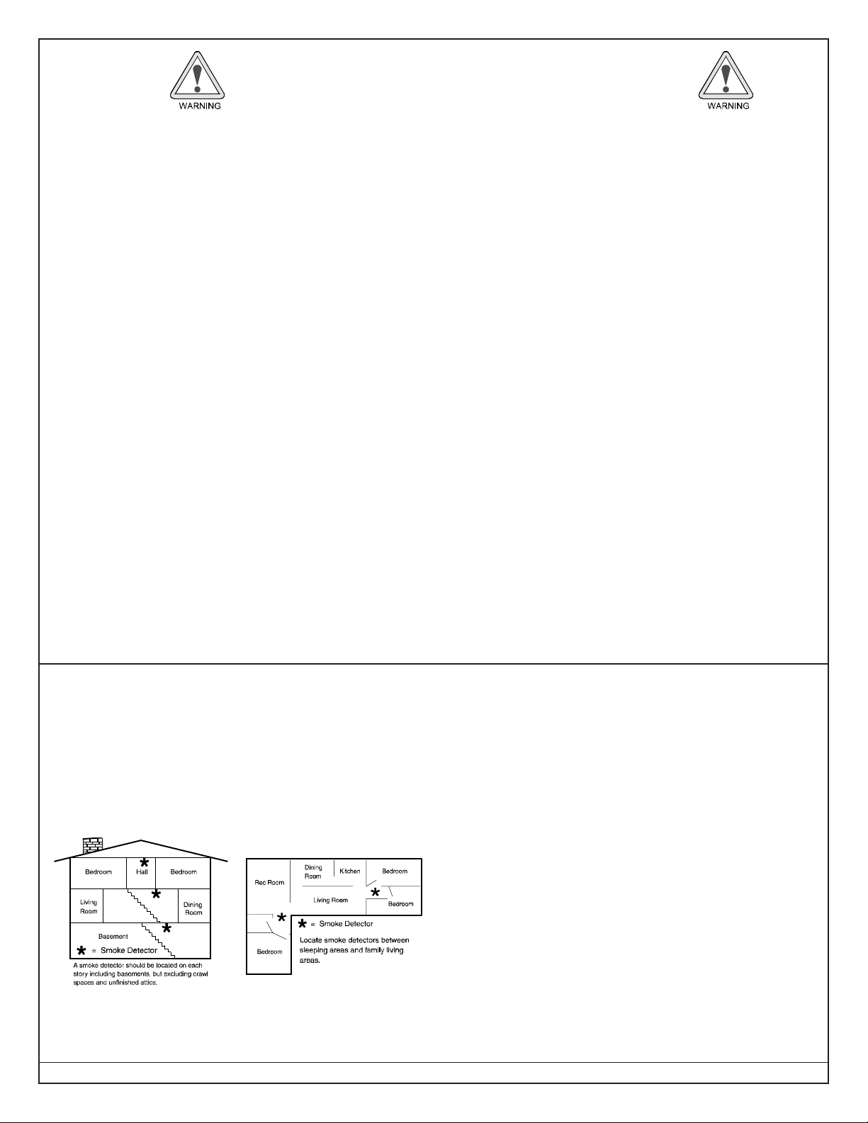
DS7400Xi ( 4+) Reference Guide Copyright © 2007 Bosch Security Systems, Inc. P/N: F01U035325-01 Page 27
7.4 Fire
Safety
No fire detection device or system should be considered 100% foolproof.
This fire alarm system can provide early warning of a developing
fire. Such a system, however, does not ensure protection against
property damage or loss of life resulting from a fire. Any fire alarm
system may fail to warn for any number of reasons (e.g. smoke not
reaching a detector that is behind a closed door).
When considering detectors for residential applications, refer to
NFPA Standard 72, “The National Fire Alarm Code.” This standard
is available at a nominal cost from: The National Fire Protection
Association, Batterymarch Park, Quincy, MA 02269.
7.4.1 If Installed in Family Residences
Adherence to the NFPA Standard 72 can lead to reasonable fire
safety when the following items are practiced:
• Minimize hazards: Avoid the three traditional fire killers: smoking
in bed, leaving children home alone, and cleaning with
flammable liquids.
• Providing a fire warning system: Most fire deaths occur in the
home, the majority, during sleeping hours. The minimum level
of protection requires smoke detectors to be installed outside of
each separate sleeping area and on each additional story of the
dwelling.
For added early warning protection, it is recommended that
detectors be installed in all separated areas including the
basement, bedrooms, dining room, utility room, furnace room,
and hallways.
7.4.2 Having and Practicing an Escape Plan
A fire warning may be wasted unless the family has planned in
advance for a rapid and safe exit from the building.
• Draw a floor plan of the entire house showing two exits from
each bedroom and two from the house. Since stairwells and
hallways may be blocked during a fire, the plan should provide
exits from bedroom windows.
Make copies of the plan and practice it with all family members.
• Pre-arrange a meeting place outside and away from the
residence. Once out of the building, all occupants should
immediately go to the pre-selected location to be accounted for.
• Provide a barricade between family members and fire, smoke,
and toxic gases (e.g. close all bedroom doors before retiring).
• Children should be instructed on opening their bedroom
windows and exiting safely from the building. If exiting is not
possible, they should be taught to stay at the open window and
shout for help until it arrives.
• In the event of a fire alarm after retiring, wake the children by
shouting to them from behind your closed door. Tell them to
keep their bedroom doors closed.
• If the top of your bedroom door is uncomfortably hot, do not open
it. There is most likely fire, intolerable heat, or smoke on the
other side. Shout to all family members to keep their bedroom
doors closed and to exit the building via alternate routes.
• If the top of the door is not uncomfortably hot, brace the bottom of
the door with your foot, and the top with one hand, then open the
door about one inch. Be prepared to slam the door shut if there
is any pressure against the door or if any hot air rushes in.
• If there is no evidence of excessive heat or pressure, leave the
room and close the door behind you. Shout appropriate
instructions to all family members and immediately leave the
building via the pre-planned routes. If heavy smoke is present,
drop to your hands and knees, or crawl to remain below the
smoke level.
7.4.3 Installation Considerations
Proper location of detection devices is one of the most critical
factors in a fire alarm system.
The following are some general considerations:
• Smoke detectors should not be installed in “dead air” spaces or
close to ventilating or air conditioning outlets because smoke
may be circulated away from the detector. Locations near air
inlets should be favored.
• Avoid areas subject to normal smoke concentrations such as
kitchens, garages, or near fireplaces.
• Do not install smoke detectors where normal area tempera-
tures are above 100° F (38° C) or below 32° F (0° C).
• Areas of high humidity and dust concentrations should be avoid-
ed.
• The edge of ceiling mounted detectors should be no closer than
4 inches (10 cm) from any wall.
• Place the top edge of wall mounted detectors between 4 and 12
inches (10 to 30 cm) from the ceiling.

Page 28 P/N: F01U035325-01 Copyright © 2007 Bosch Security Systems, Inc. DS7400Xi (4+) Reference Guide
7.5 Personal Identification Numbers
7.5.1 General Information
A PIN (Personal Identification Number) is the 4- or 6-digit code
users must enter at the keypad to gain access to the system. Your
system has the capability to assign up to 200 PINs, each four or six
digits long. A PIN may be assigned to each User Number.
PINs should never be programmed with common sequences
such as 1 2 3 4, 1 1 1 1, or 2 4 6 8 because they are easily
violated.
A User Number is the number that identifies each person using
the system. There are 200 possible User Numbers available for
use (001 through 200).
Each User Number can have only one PIN assigned to it.
Attempting to assign the same PIN to multiple User Numbers will
result in the three-beep error tone, and the entry will not be made.
User Number 001 is designated as a Master code. It can be used
to add, delete, or change other PINs. It will always have access to
all partitions regardless of how it is programmed.
User Number 001 is shipped from the factory with the PIN of 1 2 3
4. If your system has been reprogrammed for 6-digit PINs, the PIN
for User Number 001 will be 123456. This PIN should be changed
to one of your personal preference and must be programmed
as a Master code.
A Master code is one of the available authority levels which can be
assigned to a user to determine which functions that user will be
able to perform. The available authority levels are:
0 = Master: Can enter all commands, add or change PINs
in assigned partitions, change the time and
date, bypass, arm, disarm, perform system
tests, system reset and view history. User
Number 001 must have the Master authority
level. Any or all PINs can behave as a Master
code.
1 = Unlimited: Can enter all commands, bypass, arm,
disarm, system reset and perform system
tests. It can not change PINs.
2 = General: Can bypass, arm and disarm. It can not change
PINs, system reset, enter [#] [7] or any of the
[#] [8] functions.
3 = Arm Only: Can arm the system with [PIN] + [ON] arming
sequence only. It can not perform any other
functions, including disarming.
4 = Temporary: Valid only for a specified time (the PIN will
disappear upon expiration date). It can arm
and disarm the system, but can not perform
any other functions. If this is done from a
Master keypad, you must be in Single Partition
Mode. If access is assigned to more than one
partition, you must enter a Temporary PIN
expiration date for all assigned partitions (see
Changing the Expiration Date for Temporary
PINs).
5 = Duress: When the system is disarmed using the duress
code, a silent report is sent to your monitoring
service. The Duress code is intended to be
used when the user is forced to disarm the
system.
6 = Access Code: When a PIN with an Access Code is entered,
any output programmed for Access Output (i.e.
door strikes) will pulse on for 10 seconds
(works when the system is armed or
disarmed).
7.5.2 Programming PINs
PINs can only be added, changed, or removed in Master
Programming Mode, so they are not programmable from an RF
(wireless) keypad.
You should write down your entries before you enter the Master
Code Programming Mode and have them with you as you begin
programming. Make your entries promptly. If a long delay occurs in
your entries, the 3-beep error tone occurs and exits you from the
programming mode.
It is recommended that all PIN programming procedures be
performed at a DS7447/DS7447E keypad since this keypad will
provided visual prompts throughout the programming sequence.
No visual clues will be given from a D7445/DS7445i keypad. When
the programming sequence is successfully completed, both the
DS7447/DS7447E and DS7445/DS7445i keypads will signal the
seccessful completion with a long beep.
To add or change a PIN:
• Enter Master Programming Mode (press [Master PIN] + [#] [0]).
• Enter a 0 for PIN Setup programming (press [0]).
• Enter the User Number (enter a 3-digit number from 001 to 200).
• Enter the Authority Level (enter a number from 0 to 6).
• Enter the Area(s) (Partitions) to which this user will have access
(press [1], [2], [3], [4], [5], [6], [7], and/or [8] followed by [#]).
• Enter the PIN (enter any 4- or 6-digit number; do not press [#]).
• Enter the PIN again followed by [#].
To set the expiration date for an existing Temporary PIN:
• Enter Master Programming Mode (press [Master PIN] + [#] [0]).
• Enter a 3 for Date of Code Expiration Setup programming (press
[3]).
• Enter the Expiration Month (press [0] [1] for January through [1]
[2] for December).
• Enter the Expiration Day (press [0] [1] through [3] [1]). The Tem-
porary PIN will expire at Midnight on the day selected.
• Enter the Year (enter the last two digits of the year followed by
[#]).
NOTE: Entering the command sequence [Master Code] [#] [0] [3]
[#] will cause the DS7447/DS7447E keypad to read back
the temporary code expiration date.
To remove a PIN:
• Enter Master Programming Mode (press [Master PIN] + [#] [0]).
• Enter a 0 for PIN Setup programming (press [0]).
• Enter the User number of the PIN to be cancelled, followed by [#]
(enter a 3-digit number from 001 to 200, then press [#]).

DS7400Xi ( 4+) Reference Guide Copyright © 2007 Bosch Security Systems, Inc. P/N: F01U035325-01 Page 29
NOTE: User Number 001 can not be disabled in this manner.
7.6 The Master Keypad
7.6.1 General Information
Your system may include a Master keypad. A Master keypad is a
DS7447/DS7447E keypad programmed to give a user access to
all the partitions the user has access to, not just the partition in
which the Master keypad is located. This is different from a
Standard keypad in that Standard keypads only give access to the
single partition in which they are located. Commands entered at
the Master keypad will affect all the partitions to which the user has
access. If this is not desirable, the Master keypad can also be
used to control each partition individually; this is called Single
Partition Mode. Single Partition Mode allows a user to control any
or all of the partitions the user has access to on an individual (one-
by-one) basis (see section 7.6.3 for more information on Single
Partition Mode).
NOTE: In order to use the Master keypad, your PIN must be
assigned to the partition in which the Master keypad is
located.
7.6.2 Master Keypad Displays
Master keypad displays will differ slightly from Standard keypads.
The Master keypad display will scroll the Status of each partition,
followed by the partition number. For example, if all partitions are
armed, the Master keypad will scroll through the following displays:
A
rmed
a
rea 1
Armed
area 7
Armed
area 2
Armed
area 6
Armed
area 3
Armed
area 4
Armed
area 5
Arme
d
area
8
If only partitions 1, 2, 3, 4, 6, and 8 are armed, the Master keypad
will scroll through the following displays:
A
rmed
a
rea 1
Ready to Arm
area 7
Armed
area 2
Armed
area 6
Armed
area 3
Armed
area 4
Ready to Arm
area 5
Arme
d
area
8
Displays for partitions that are Not Ready will display in the same
manner.
The chart at the bottom of this page will help you understand what
each LED function of the Master keypad represents.
7.6.3 Single Partition Mode
Single Partition Mode is used to control partitions on a “one at a
time/one by one” basis from the Master keypad.
To enter the Single Partition Mode, enter your [PIN], then press the
[#] key twice. This will call up the first partition you have access to.
Enter the command sequence you wish for this partition. You do
not need to use your PIN again. To move on to the next partition you
have access to, press the [#] key twice.
T o exit the Single Partition Mode, hold the [*] key down for 2 seconds.
The system will also automatically drop out of Single Partition
Mode after 40 seconds without a keypad entry.
Example of accessing Single Partition Mode
• Enter your [PIN], followed by the [#] key twice: [1] [2] [3] [4] [#] [#].
• The first partition you have access to will be displayed: “Ready
to Arm. Cafeteria.”
• Complete the command sequence (in this case arming) you
wish for this partition: [#] [On].
• Move to the next partition you have access to by pressing the [#]
key twice: [#] [#].
• The next partition you have access to will be displayed: “Ready
to Arm. Office.”
• Complete the command sequence you wish for this partition.
• After you have completed all the command sequences for the
partitions you have access to, exit Single Partition Mode by
pressing the [*] key for two seconds.
7.6.4 Arming from the Master Keypad
To arm all the Partitions to which you have access:
• [PIN] + any Arming Command Sequence. This will arm all the
partitions to which you have access even if they are already
armed.
To arm only some of the Partitions to which you have access:
• [PIN] + [#] + [#]. This puts you into Single Partition Mode.
• The first partition to which you have access is displayed: “Ready
to Arm. Cafeteria.”
• Enter the Arming Command Sequence you want for this parti-
tion.
• [#] + [#] opens the next partition to which you have access.
• The next partition to which you have access is displayed: “Ready
to Arm. Office.”
• Enter the Arming Command Sequence you want for this parti-
tion.
• After arming any or all partitions to which you have access, you
may exit Single Partition Mode by holding the [*] key for at least
two seconds. The system will also drop out of Single Partition
Mode after 40 seconds without a keypad entry.
7.6.5 Disarming from the Master Keypad
To disarm all the Partitions to which you have access:
• [PIN] + [Off]. This will disarm all the partitions to which you have
access even if they are already disarmed.
To disarm only some of the Partitions to which you have access:
• [PIN] + [#] + [#]. This puts you into Single Partition Mode.
• The first partition to which you have access is displayed: “Armed.
Cafeteria.”
• If you wish to disarm this partition, enter [Off]. If not, go to the next
step.
• [#] + [#] opens the next partition to which you have access.
• The next partition to which you have access is displayed: “Armed.
Office.”
• If you wish to disarm this partition, enter [Off]. If not, go to the next
step.
• After disarming any or all partitions to which you have access,
you may exit Single Partition Mode by holding the [*] key for at
LED Off Flashing On
Armed
(red)
All partitions are disarmed. One or more partitions are armed, or
an alarm ha s occurred.
All Partitions are armed, and no
alarms have occurred.
Status
(green)
Not ready to arm (if the Armed LED is
On, all partitions are armed).
One or more zones are bypassed. All partitions are ready to arm.
Power
(green)
The Control Panel has lost all power;
no AC or b attery.
Control Panel problems exist.
See Err or Di s pla ys.
Normal Operation.
The Control Panel is running on AC
power with no problems,
Fire
(red)
There are no fire alarms. A fire zone is in alarm. A fire trouble condition exists.
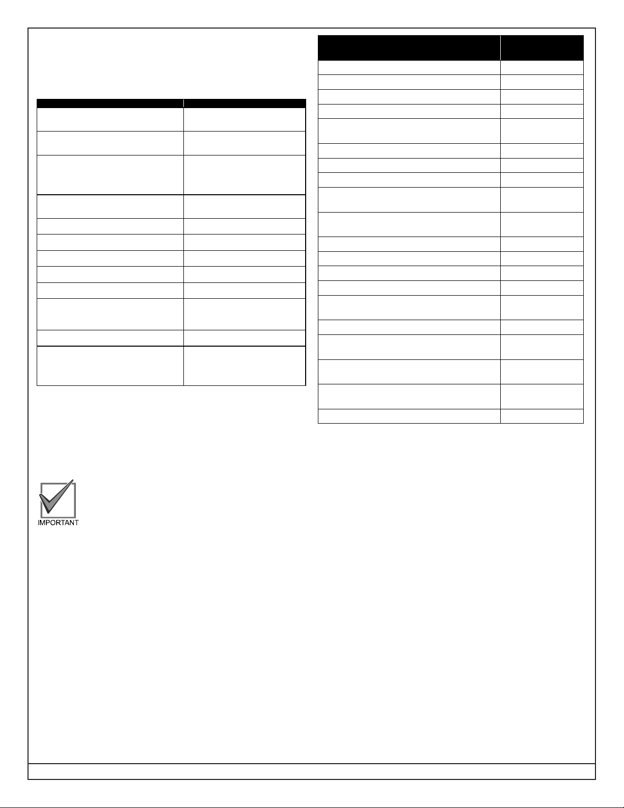
Page 30 P/N: F01U035325-01 Copyright © 2007 Bosch Security Systems, Inc. DS7400Xi (4+) Reference Guide
least two seconds. The system will also drop out of Single Par-
tition Mode after 40 seconds without a keypad entry.
7.7 Keypad Error Displays
7.7.1 General Information
Display Meaning
DS7445/DS7445i:
Power LED flashing
DS7447/DS7447E:
Control Trouble Ente r #87
There is an E rror Message. To
display the message, enter [PIN] + [#
]
[8] [7].
DS7445/DS7445i:
LED 1 On
DS7447/DS7447E:
AC Power Failure
There is a po we r fa i lu r e, and t h e
panel is operating on backup battery
power.
DS7445/DS7445i:
LED 2 On
DS7447/DS7447E:
Battery Tro uble*
If the system has just been through a
power failure, wait at least two hours
for the battery to rechar g e, the enter
[PIN] + [System Reset] to perform a
battery test,
DS7445/DS7445i:
LED 3 On
DS7447/DS7447E:
Communicator Er r* *
The communicator failed to
communicate with the Central
Station.
DS7445/DS7445i:
LED 4 On
DS7447/DS7447E:
System Fault
Internal error in the control circuitry or
optional circuitry. See System Faults.
DS7445/DS7445i:
LED 5 On
DS7447/DS7447E:
Keypad Fault
One of the keypads is not responding
to the Control Panel.
DS7445/DS7445i:
LED 6 On
DS7447/DS7447E:
Keypad Tam per
One of the keypad housings has
been op ened.
DS7445/DS7445i:
LED 7 On
DS7447/DS7447E:
Multiplex Bus
The multiplex bus is defe c tive or has
been shorted.
DS7445/DS7445i:
LED 8 On
DS7447/DS7447E:
Aux. Powe r Faul t
The auxiliary power has been
shorted.
DS7445/DS7445i:
not applicable
DS7447/DS7447E:
Zone Tr ou bl e
One of the zones is not responding to
the Control Panel. This may also be
displ ayed during power -u p; i f so,
ignore it.
DS7445/DS7445i:
not applicable
DS7447/DS7447E:
RF
Indicates a problem with an RF
(wireless) zone.
DS7445/DS7445i:
not applicable
DS7447/DS7447E:
Dirty Chamber
One of the multiplex smoke detectors
has failed the sensitivity test and may
require cleaning or replacement. The
keypad beep may be cleared by
entering [PIN] + [Off].
Error Displays can only be read when the control is disarmed.
Some Control Panel Errors, such as battery trouble and any RF
troubles, will cause the keypad sounders to beep every 10 seconds.
The keypad sounders may be silenced for 4 hours by entering:
[PIN] + [Off].
The sounders will continue to resound until the problem is fixed.
To Clear a display, enter:
[PIN] + [System Reset].
Clear the Error Display only on the advice of your
installing company or if you are certain the problem
has been remedied.
NOTE: System faults may be read from any keypad because they
are system-wide. All other Error Displays are limited to
the partition the standard keypad is in. If you are on a
Master keypad, you may read Error Displays one partition
at a time.
7.7.2 System Faults
System faults are designated as follows:
[#] [8] [7] will display [#] [8] [9] will
display
RAM Fault System Fault 01
ROM Fault System Fault 02
EEPROM Fault System Fault 03
Ground Fault System Fault 04
2Ph/Bell Fault = loss of communication to
DS7420i
System Fault 10
Line 1 Fault = DS7420I phone line 1 fault System Fault 11
Line 2 Fault = DS7420I phone line 2 fault System Fault 12
Bell Fault = DS7420i bell circuit fault System Fault 13
Aux. Relay Fault = DS7420I auxiliary relay
fault
System Fault 14
Oct. Relay Fault = loss of communication to
DS7488
System Fault 20
Reserved for older panels System Fault 50
AR IB Queue Full = modem buffer full System Fault 51
AR Host Down = network data switch down System Fault 52
AR Unreg. Modem = modem not registered System Fault 53
AR Power Fail = power source below
defined threshold
System Fault 54
AR Network Lost = loss of network System Fault 55
AR Modem HW Err = modem hardware
error
System Fault 56
AR Modem SW Err = modem software
error
System Fault 57
AR Opt. Bus Err = loss of communications
to ARDIS module
System Fault 58
AR Corrupt MSG = message error System Fault 59
7.7.3 Event History
The History Buffer stores the last 400 events in memory. The
DS7447/DS7447E can display all of these events. If this test is
performed from a Master keypad, it must be in Single Partition
Mode. The DS7445/DS7445i will only display those zones (1-8)
that have alarmed since the last Event History Readback. The
RF3341 cannot display history events.
To readback the Event History Buffer:
• Press [PIN] + [#] [8] [9]. On a DS7447/DS7447E keypad, the last
event to take place will be displayed. On a DS7445/DS7445i
keypad, the zone LEDs for any zones that have alarmed since
the last Event History Readback in that partition will flash.
• Scroll through the events using the [9], [6], and [#] keys as follows:
To begin scrolling back through the events, press the [#] key. The
[#] key will scroll you back through the history line by line. The [9]
key will scroll you back in reverse chronological order by event. A
[6] will scroll you back up through the events (toward the most
recent) by event.
Each event consists of two or three lines or display screens. The
first line/screen will be the event title and user. The second line/
screen will be the date of the event or the change being made. If
there is a third line/screen, it will be the date of the change.
NOTE: When performing this from a Master keypad, each partition
will display its own history.
• T o exit the Event History Mode, press the [*] key or wait 20 seconds
and the keypad will exit automatically.
 Loading...