


D7412G
EN
Program Entry Guide
Control Panels
D9412G/D7412G
D9412G/D7412G | Program Entry Guide | EN | 2
Bosch Security Systems | 1/04 | 47775E
Trademarks
CoBox is a registered trademark of Lantronix
®
.
Windows
®
is either a registered trademark of Microsoft
Corporation in the United States and/or other
countries.
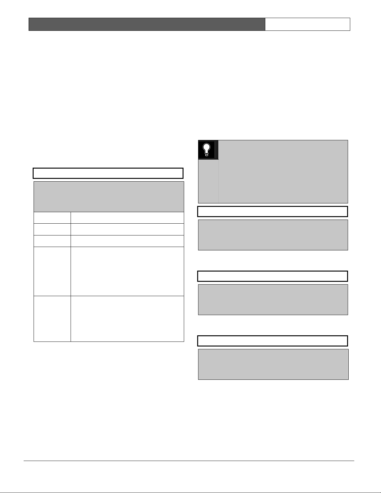
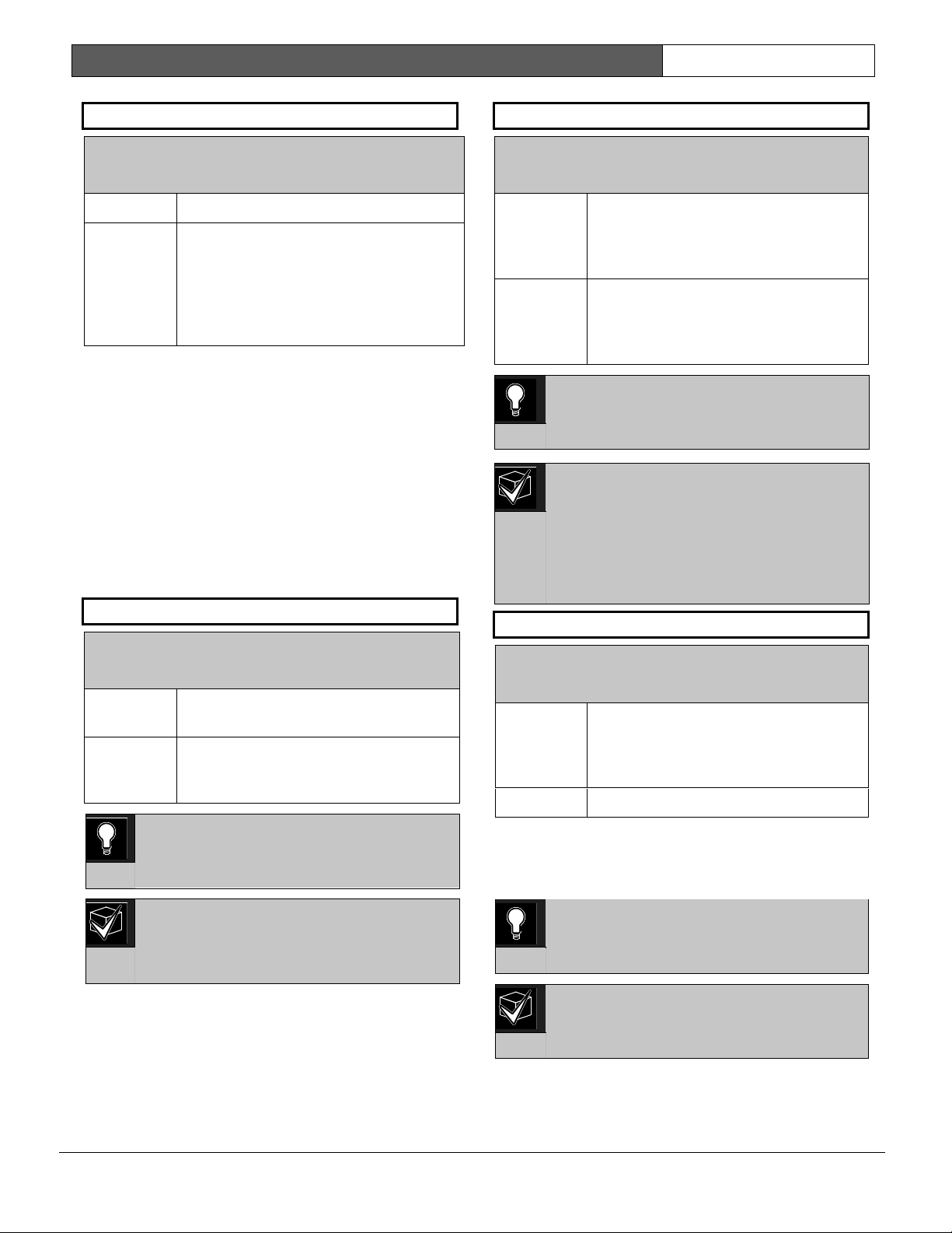
Documentation Conventions
Type Styles Used in this Manual
To help identify important items in the text, the
following type styles are used:
Bold text
Usually indicates selections that
you might use while programming
your control panel. It can also
indicate an important fact.
Italicized text
Used to refer the user to another
part of this manual or another
manual entirely. It can also used to
symbolize names for records that
the user creates.
Courier Text
Indicates what can appear on the
Remote Programmer’s display,
command center/keypad or
internal printer.
[CAPITALIZED
TEXT]
Used to indicate that a specific key
should be pressed.
Promp
t
A thick border is used to indicate a
main programming entry as seen
in the Remote Programmer’s
Display. It is used as a section
heading and screen example.
Shaded boxes indicate
programmer prompts that are only
available when Custom or View
events are selected.
Sub-Promp
t
A dashed border indicates a sub
entry under a main programming
entry.
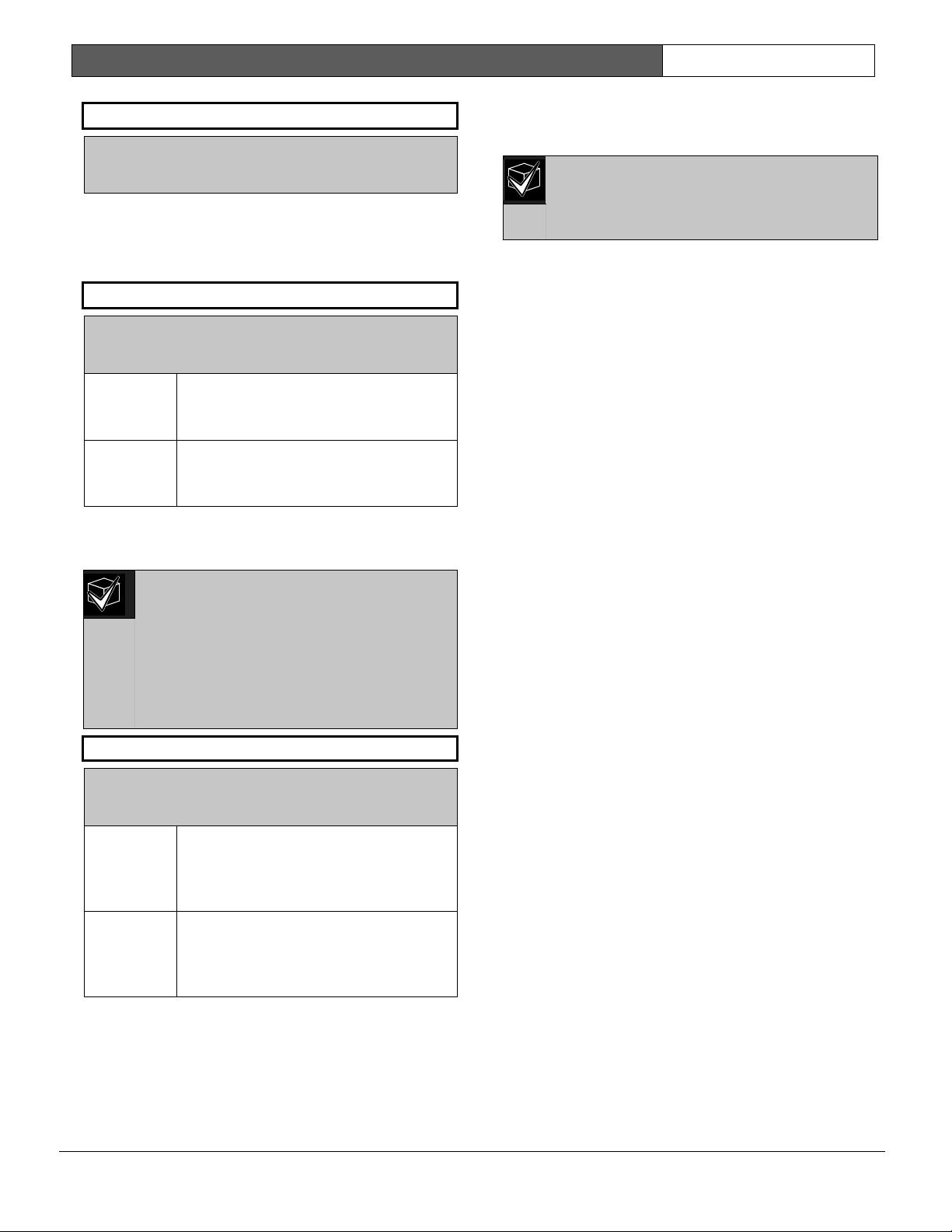
Tips, Notes, Cautions and Warnings
Throughout this document helpful tips and notes are
presented concerning the entire application and/or
programming the unit. They are displayed as follows:
Application Tip:
These are helpful shortcuts or reminders in
using the unit.
Application Note:
These are notes and clarifications of
different aspects of the application.
0101
0101
0101
Programming Notes:
These cover notes and clarifications
specific to programming the unit.
0101
0101
0101
Programming Tip:
These are helpful shortcuts or reminders for
programming the unit.
Important Notes
These notes should be heeded for
successful operation and programming.
Warning!
These warn of the possibility of physical
damage to the operator, program and/or
equipment. Use this when there is an
increased risk of physical damage to the
operator (severe injury or death) or
equipment (destruction of physical
components).
Caution
These caution the operator that physical
damage to the program and/or equipment.
Access control tip.

D9412G/D7412G | Program Entry Guide | Table of Contents EN | 3
Bosch Security Systems | 1/04 | 47775E
Table of Contents
1.0 Introduction.......................................................5
1.1 How to use this Program Entry Guide............. 5
1.2 Literature Referenced.........................................5
1.3 Differences Between the D9412G and
D7412G ...............................................................5
1.4 New Features....................................................... 6
1.5 Product Handlers................................................8
1.6 Programming Options........................................8
1.7 Programming the Control Panel with the
D5200 Programmer............................................9
2.0 9000MAIN ........................................................11
2.1 Phone .................................................................11
2.2 Phone Parameters.............................................12
2.3 Routing ..............................................................15
2.3.1 Called Party Disconnect .................................. 15
2.3.2 Route Number Groups: Which Has the
Highest Priority?...............................................15
2.3.3 Programming a Primary and Backup
Destination ........................................................16
2.3.4 Enhanced Routing............................................16
2.3.5 Programming a Duplicate Report...................16
2.3.6 Routing Destination Communication
Failures............................................................... 16
2.3.7 Message Prioritization within a Route
Number.............................................................. 16
2.3.8 Dialing Attempts...............................................16
2.4 Enhanced Routing............................................23
2.4.1 Programming a Primary and Backup
Destination ........................................................23
2.4.2 Programming a Duplicate Report...................24
2.5 Power Supervision............................................27
2.6 Printer Parameters ............................................29
2.7 RAM Parameters ..............................................31
2.7.1 Uploading and Downloading Reports ...........31
2.7.2 Log Threshold Reports ....................................31
2.7.3 RAM Callback Reports ...................................31
2.8 Miscellaneous....................................................34
2.9 Area Parameters................................................34
2.9.1 Area Parameters................................................34
2.9.2 Programming Account Numbers in 9000
Series Control Panels, versions 6.20 and
Higher ................................................................35
2.9.3 Shared-Area Characteristics ............................40
2.9.4 Bell Parameters .................................................40
2.9.5 Open/Close Options........................................42
2.10 Command Center.............................................46
2.10.1 Cmd Cntr (Command Center) Assignment.. 46
2.10.2 Area Text .......................................................... 50
2.10.3 Custom Function.............................................. 51
2.11 User Interface ................................................... 53
2.11.1 Commands........................................................ 53
2.11.2 Command Center Selections.......................... 53
2.11.3 Authority Level Selections.............................. 59
2.12 Function List..................................................... 67
2.13 Relay Parameters ............................................. 67
2.13.1 Area Relays....................................................... 68
2.13.2 Panel-Wide Relays........................................... 71
3.0 RADXUSR1/RADXUSR2 ............................ 73
3.1 Passcode/Token Worksheet............................ 73
3.1.1 User Groups...................................................... 73
3.1.2 Passcodes........................................................... 73
3.1.3 User Group Window ....................................... 73
3.1.4 Authority Level by Area ................................. 73
3.1.5 User Name........................................................ 73
3.1.6 Tokens/Cards ................................................... 73
3.1.7 Reporting and Logging.................................... 73
4.0 RADXPNTS..................................................... 77
4.1 Point Index ....................................................... 77
4.1.1 Point Responses................................................ 81
4.2 Point Assignments............................................ 91
4.3 COMMAND 7 and COMMAND 9 ............. 94
5.0 RADXSKED.................................................... 95
5.1 Windows ........................................................... 95
5.1.1 Opening and Closing....................................... 95
5.1.2 User Group Windows.................................... 102
5.2 Skeds................................................................ 104
5.3 Holiday Indexes............................................. 113
5.3.1 Add/Change/Delete ...................................... 113
5.3.2 View Holidays................................................ 114
6.0 RADXAUX1.................................................. 115
6.1 Introduction .................................................... 115
6.2 RAM IV and D5200 Handler
Requirements.................................................. 115
6.3 SDI Automation ............................................. 115
6.4 SDI RAM Parameters.................................... 116
6.4.1 User Interface Modifications for
COMMAND 43............................................. 117
6.4.2 Using an External Modem............................ 118
6.5 Enhanced Communications.......................... 122
6.5.1 Programming Path Numbers and
IP Addresses ................................................... 123
6.6 SDI RAM/Enhanced Communications
Configuration.................................................. 125
6.6.1 Route Group Attempts .................................. 126

D9412G/D7412G | Program Entry Guide | Table of Contents EN | 4
Bosch Security Systems | 1/04 | 47775E
6.7 Miscellaneous..................................................127
6.8 Cross Point Parameters..................................128
7.0 RADXAXS .....................................................131
7.1 Door Profile.....................................................131
7.2 Strike Profile....................................................133
7.3 Event Profile....................................................134
Programming Prompts Directory ...........................136
Figures
Figure 1: Pager Display Fields.......................................25
Figure 2: Account Number Entry .................................36
Figure 3: User Group 122 Example..............................74
Figure 4: Example Opening Window Timeline (using
two Opening Windows on same day)..........97
Figure 5: COMMAND 43 Flow Chart.......................117
Figure 6: RAM IP Address Prompts...........................118
Figure 7: Com Port Selection within
HyperTerminal.............................................120
Figure 8: External Modem Connection .....................120
Figure 9: Path # IP Add1 to Add4 .............................123
Figure 10: Poll Rate Timeline......................................124
Tables
Table 1: Literature Referenced .....................................5
Table 2: Differences between the D9412G and
D7412G............................................................5
Table 3: New Features................................................... 6
Table 4: Product Handlers ............................................8
Table 5: Programming Error Displays......................... 9
Table 6: Modem IIIa
2
Communication Format Data -
User ID Numbers..........................................13
Table 7: Modem IIIa
2
Communication Format Data –
Point Numbers ..............................................13
Table 8: Zones ..............................................................13
Table 9: Diagnostic Reports........................................ 18
Table 10: Burglar Reports .............................................18
Table 11: User Reports..................................................19
Table 12: Test Reports...................................................20
Table 13: Diagnostic Reports........................................ 21
Table 14: Relay Reports................................................21
Table 15: Auto-Function Reports .................................21
Table 16: RAM Reports ................................................22
Table 17: Point Reports.................................................22
Table 18: User Change Reports ................................... 23
Table 19: Access Reports .............................................. 23
Table 20: Event Descriptions, Priorities, and
Numbers.........................................................26
Table 21: Programming Four Digit Account
Numbers ........................................................ 35
Table 22: Programming Ten Digit Account
Numbers ........................................................ 35
Table 23: Verify Time................................................... 37
Table 24: CF### Custom Function Keystrokes........ 52
Table 25: Command Center Programming
Choices .......................................................... 53
Table 26: Authority Level Selections .......................... 59
Table 27: L## Secure Door-Door Mode
Definitions ..................................................... 62
Table 28: BSFK User Code Report ............................. 74
Table 29: P### BFSK/Relay Codes/Relays.............. 93
Table 30: Point Text for Points 240 to 247................. 93
Table 31: Window Selections....................................... 95
Table 32: Programming for Two Same Day Opening
Windows (see Figure 4)................................. 98
Table 33: Programming to Link Two Days over
Midnight ........................................................ 98
Table 34: W# Close Window Stop Programming
Example......................................................... 99
Table 35: Opening/Closing Windows Worksheet... 101
Table 36: Opening/Closing Windows....................... 101
Table 37: Normal Store Hours* ................................. 101
Table 38: Delivery Schedule*..................................... 102
Table 39: Monthly Auditor’s Schedule*.................... 102
Table 40: Cross Point Ranges Within Groups .........128
D9412G/D7412G | Program Entry Guide | 1.0 Introduction EN | 5
Bosch Security Systems | 1/04 | 47775E
1.0 Introduction
1.1 How to use this Program Entry Guide
This guide addresses the programming of the
D9412G/D7412G Control Panels only, and should not
be used in conjunction with other control panels.
Although this guide specifically refers to the D9412G
Control Panels, it can be used for programming the
D7412G Control Panels. Differences between the
D9412G and D7412G are shown Table 2.
1.2 Literature Referenced
Throughout this guide, references are made to other
documents. See Table 1 for a part numbers list of the
referenced literature for ordering purposes.
Read the following documents before installing and
programming the products.
Table 1: Literature Referenced
Document Name Part Number
1.
D1255 Installation Instructions
74-06819-000
2.
D1256/D1257 Installation
Instructions
74-06925-000
3.
D1260 Installation Guide
48101
4.
D1260 Owner’s Manual
50410
5.
D5200 Operations Manual
74-06176-000
6.
D6500 Report Directory
74-04651-001
7.
D6600 Communications
Receiver/Gateway Computer
Interface Manual
39963
8.
D720 Installation Instructions
74-06918-000
9.
D9210B Operation and
Installation Guide
32206
10.
D9210B Program Entry Guide
32207
11.
D9210B Program Record Sheet
32208
12.
D9412G/D7412G Operation
and Installation Guide
43488
13.
D9412G/D7412G Program
Record Sheet
47488
14.
RPS Operations Manual
38849
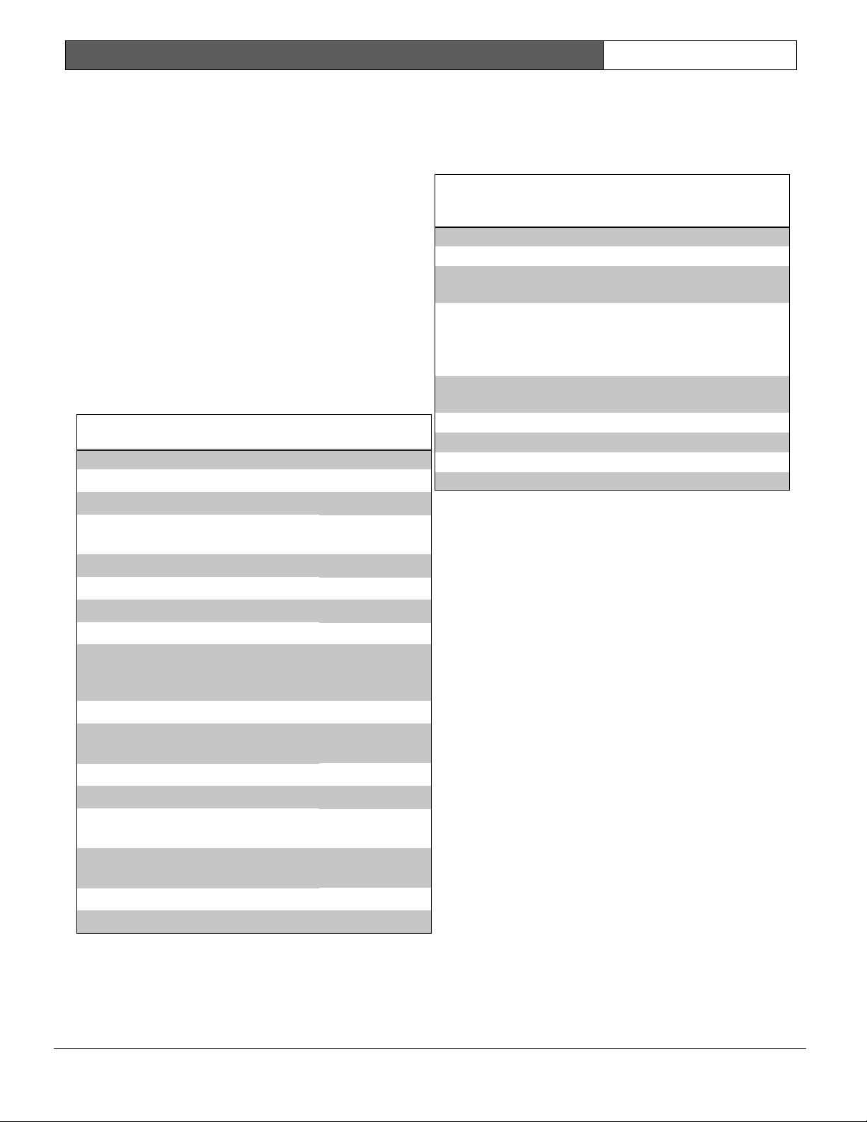
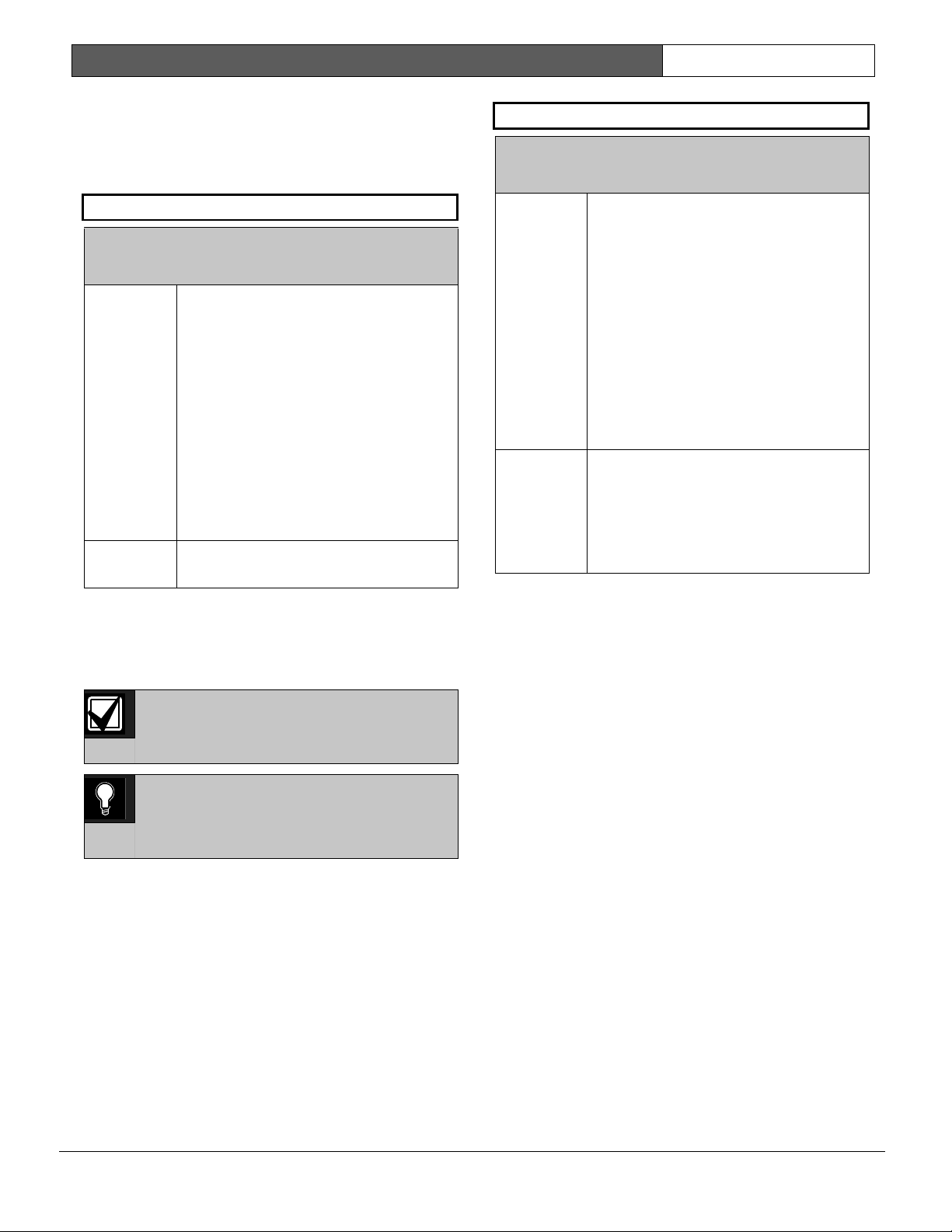
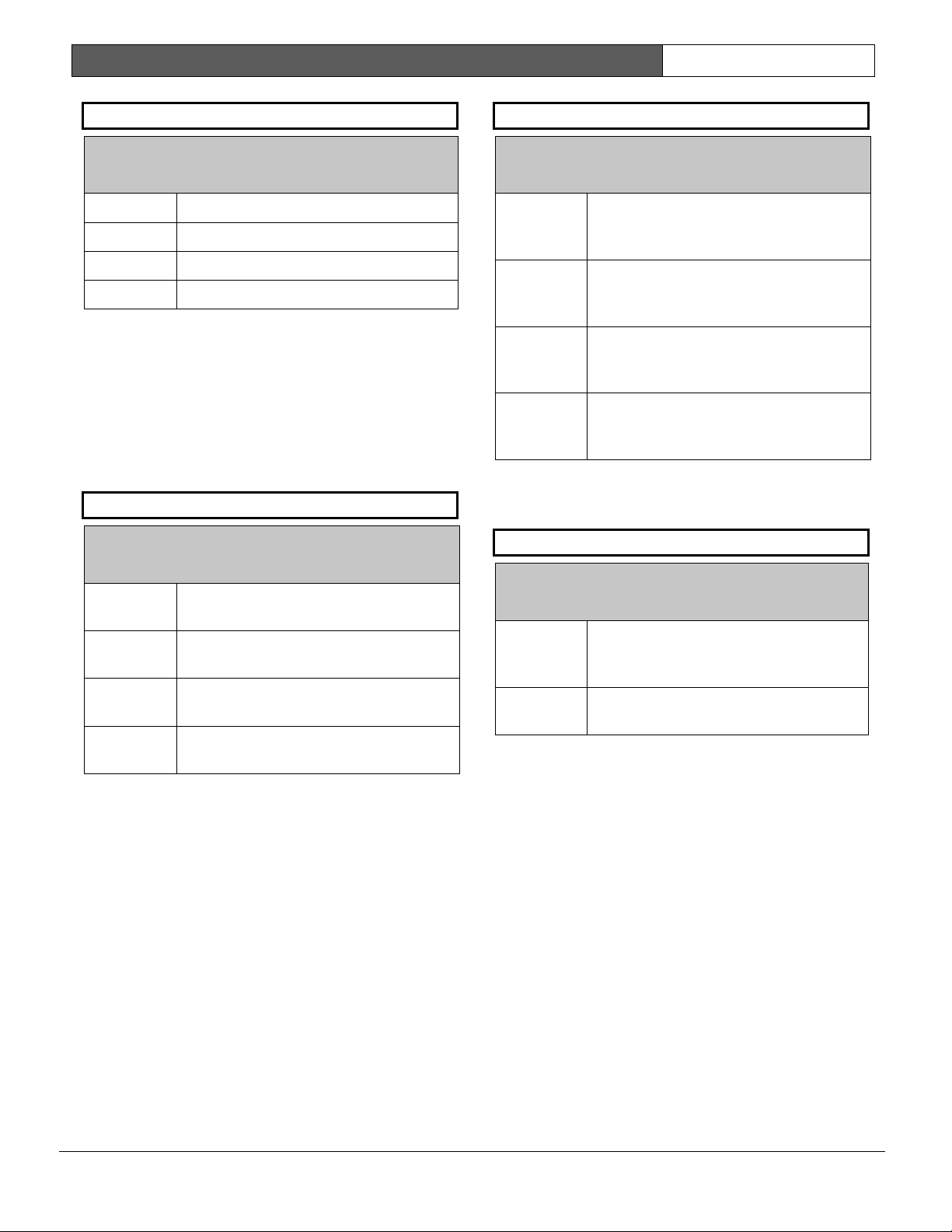
1.3 Differences Between the D9412G
and D7412G
Table 2 describes the differences between the D9412G
and the D7412G Control Panels.
Table 2: Differences between the D9412G and
D7412G
Features D9412G D7412G
Access Control Yes
Eight Doors
Yes
Two Doors
Expanded users
Arm/disarm
Passcodes
Cards/tokens
249
996
99
396
Passcode-protected
custom functions
16 4
Number of printers 3 1
Number of points 246 75
Number of relays 128 64

D9412G/D7412G | Program Entry Guide | 1.0 Introduction EN | 6
Bosch Security Systems | 1/04 | 47775E
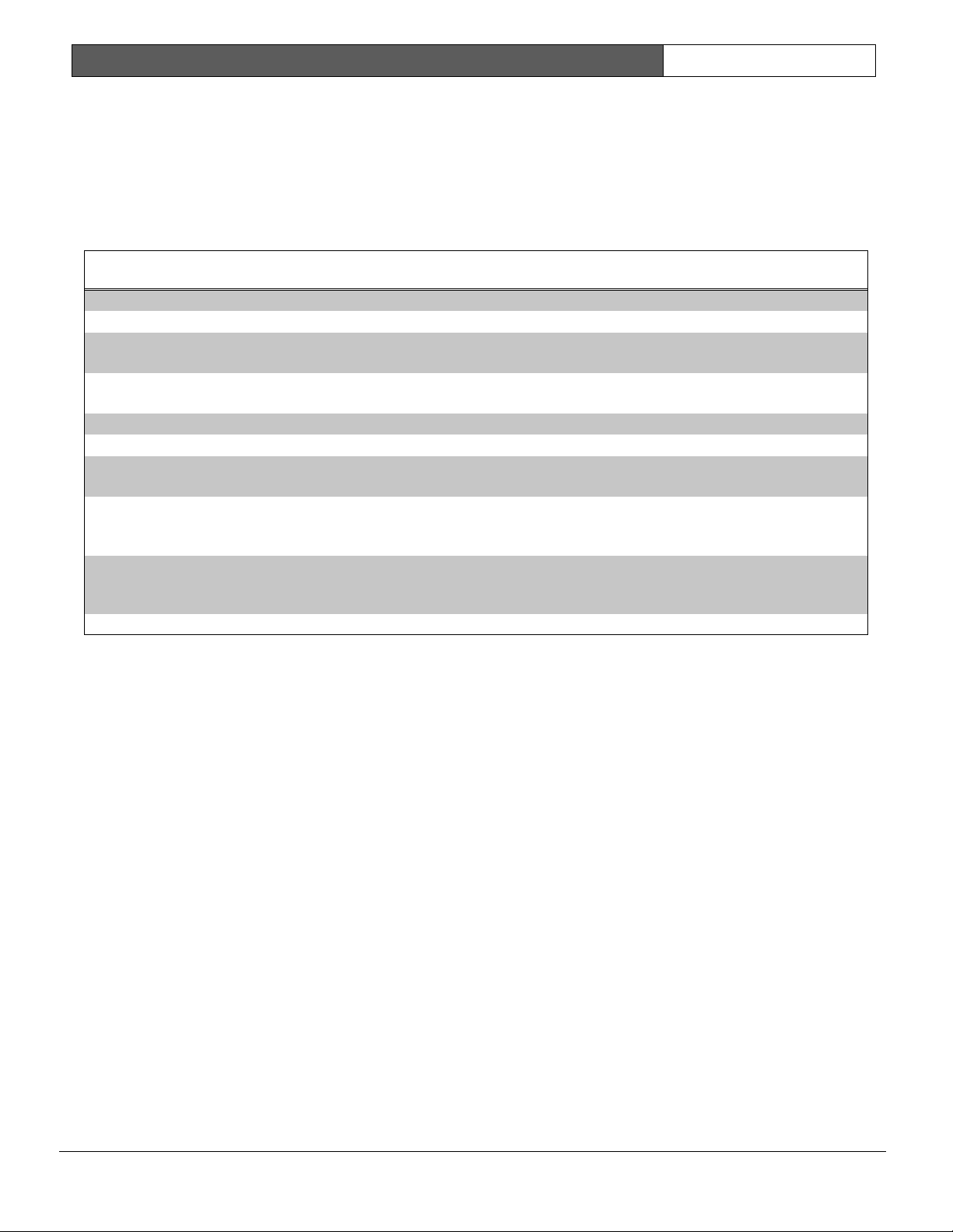
1.4 New Features
The items shown Table 3 are new features added to the D9412G/D7412G Control Panels since version 6.10.
Table 3: New Features
Feature Description
Ground Fault Detect
(Version 6.10)
For the D9412G/D7412G to detect ground fault conditions, the earth ground terminal on the
control panel was electrically isolated from all other terminals. A ground fault detect enable switch
(S4) was added to the control panel and is located under Terminal 10, earth ground. For more
information on the operation of this function, see the D9412G/D7412G Operation and Installation
Guide (P/N: 43488).
Added Feature when
Using Ground Fault
Detect (Version 6.10)
When ground fault detect is enabled (S4 closed), Points 1 to 8 can be used for non-powered fire-
initiating devices; such as, heat detectors, 4-wire smoke detectors, or pull stations. A D125B
Powered Loop Interface or a D129 Dual Class A Interface Module is no longer required when
connecting non-powered fire-initiating devices to Points 1 to 8.
Fire Supervision Restoral
Event (Version 6.20)
A new Fire Supervision Restoral Event was added to the Fire Events route group allowing this
event to be transmitted when a Fire Supervision point restores to normal. Previous versions sent
either a Fire Alarm Restore or Fire Trouble Restore Event.
AC Fail Time modification
(Version 6.20)
The AC Fail Time entry was modified to allow additional programming flexibility. In previous
versions, the AC Fail Time was made in either minutes or seconds (depending on the firmware
version). However, version 6.20 allows you to select minutes or seconds and the length of time the
AC Fail message is delayed (6 hours or 12 hours) after the occurrence. See the AC Fail Time
prompt in Section 2.5 Power Supervision for additional information.
Fire Trouble Resound
(Version 6.20)
The D9412G and D7412G can be programmed to re-sound the fire trouble tone at command
center(s) at midnight or at noon if the Fire point is still in a trouble condition. See the A # Silent
Alarm prompt in Section 2.13.1 Area Relays for additional information.
Perimeter Armed Relay
Operation (Version 6.20)
The D9412G and D7412G can be programmed to activate a relay output when an area becomes
Perimeter Armed using COMMAND 2 (Perimeter Instant), COMMAND 3 (Perimeter Delayed), or
COMMAND 8 (Perimeter Partial). See the A # Silent Alarm prompt in Section 2.13.1 Area Relays
for additional programming information.
Poll Rate Operation
(Version 6.20)
In versions 6.00 and 6.10, a poll rate can be programmed to supervise the connection between the
control panel, D9133TTL-E, and the D6600 Receiver. If the supervision connection was lost, future
events were still routed to the Primary Path first before attempting the Backup Path. In version 6.20,
the ability to instruct the control panel to automatically use the Backup Path if the Primary Path is
compromised was added.
Programming Account
Numbers (Version 6.20)
The 9000MAIN version 1.12 handler and version 6.20 firmware and higher now can program a
four-digit or ten-digit account number for each area. See the A# Acct Number prompt in Section
2.9 Area Parameters for additional programming information.
The D9412G and D7412G can now be programmed to group multiple points together in a Cross
Point configuration mode. This feature, more commonly known as Cross Zoning, instructs the
control panel to delay its alarm response for a programmed period of time before additional points
go into an alarm condition, verifying the burglar alarm condition. To program the D9412G or
D7412G for Cross Point operation, review the following:
Location Item
Table 10
R# Unverified Evt
Section 4.1.1 Point Responses
Cross Point prompt
Cross Point Operation
(Version 6.30)
Section 6.8 Cross Point Parameters
Cross Point prompt
D1260 Alpha V Command
Center Support (Version
6.30)
The new D1260 Alpha V Command Center boasts an easy-to-read, four-line by twenty-character
LCD display, eight soft keys for displaying simple selections, and the standard Bosch Security
Systems command structure (COMMAND 1, COMMAND 2, and so on). See the Enhanced
Command Center prompt in Section 2.10.1 Cmd Cntr (Command Center) Assignment for further
programming information.

D9412G/D7412G | Program Entry Guide | 1.0 Introduction EN | 7
Bosch Security Systems | 1/04 | 47775E
Table 3: continued
Feature Description
Fire Trouble Resound
Mode (Version 6.30)
To help our Bosch Security Systems dealers program this feature more easily, the prompt, Fire
Trouble Resound was added to Section 6.7 Miscellaneous.
Sked Functions (Version
6.30)
The D9412G and D7412G can be programmed to execute Sked 28 (Expanded Off-Normal Test
Reports) and Sked 29 (Non-Expanded Off-Normal Test Reports). These new skeds allow the
control panel to generate Expanded or Non-Expanded Off-Normal Test Report Event instead of the
previously used Expanded Test Report or Non-Expanded Test Report Event. See the S## Function
Code prompt, 28 and 29, in Section 5.2 Skeds for further programming information.
Inovonics Premises RF
Compatibility
(Version 6.30)
In version 6.30 you can add Inovonics Premises RF. Through the use of the D8125INV Wireless
Interface, which connects directly to ZONEX 1 and ZONEX 2 (D9412G only) and an Inovonics
FA400 Wireless Receiver, up to 238 wireless transmitters can be added to a D9412G (up to 67
can be added to the D7412G). Each D8125INV supports up to 119 wireless transmitters (or 67 if
connected to a D7412G). Transmitters added to the system can be monitored for activation,
tamper, and low battery conditions. The FA400 Receiver is also supervised and the Inovonics
Repeaters can be programmed to be supervised.
High Speed PSTN RPS
Communications (Version
6.30)
Using an off-the-shelf modem (capable of communicating at 9600-baud) and a D9133DC Direct
Connect Programming Module, RPS can now communicate with a D9412G or D7412G at 9600-
baud instead of using the on-board 300 baud modem chip. This is especially useful for those
accounts requiring constant RPS communication sessions, such as passcode or token changes or
copying the logger. The use of this feature dramatically reduces the time (and money) spent online
with the control panel. See Section 6.4.2 Using an External Modem for programming details on the
operation of this feature.
New Buzz On Fault Mode
(Version 6.30)
A Buzz on Fault Mode (Option 3) was added to the point index parameters. For points with Option
3 enabled, a trouble tone is generated at the keypad when the point is off-normal while the area is
disarmed. The user (by either passcode or COMMAND 4) cannot silence this buzz. It silences
automatically when the point restores. Apply this feature when you want to monitor specific points
and produce an audible annunciation at the command center when the point is faulted. For
example, this feature could be used for a driveway sensor or a vestibule door that alerts you to an
approaching individual.
Disarm Now message
enhancement (Version
6.30)
The DISARM NOW text that appears during entry delay was modified beginning with version 6.30.
The new text that appears alternates between DISARM NOW and the point text of the point that
caused the area to go into entry delay. For example, if the point causing the area to go into entry
delay was named Front Office Dr, then the control panel displays DISARM NOW then FRONT
OFFICE DR during the entirety of entry delay.
Panel Buzzer (Version
6.30
Beginning with version 6.3 and higher, the control panel’s on-board buzzer pulses 1 second on, 1
second off, if a supervised command center no longer responds to polls from the control panel. The
buzzer is silenced when the supervised command center begins responding to polls again or when
[COMMAND][4] is entered from an operational command center.
D9412G/D7412G | Program Entry Guide | 1.0 Introduction EN | 8
Bosch Security Systems | 1/04 | 47775E
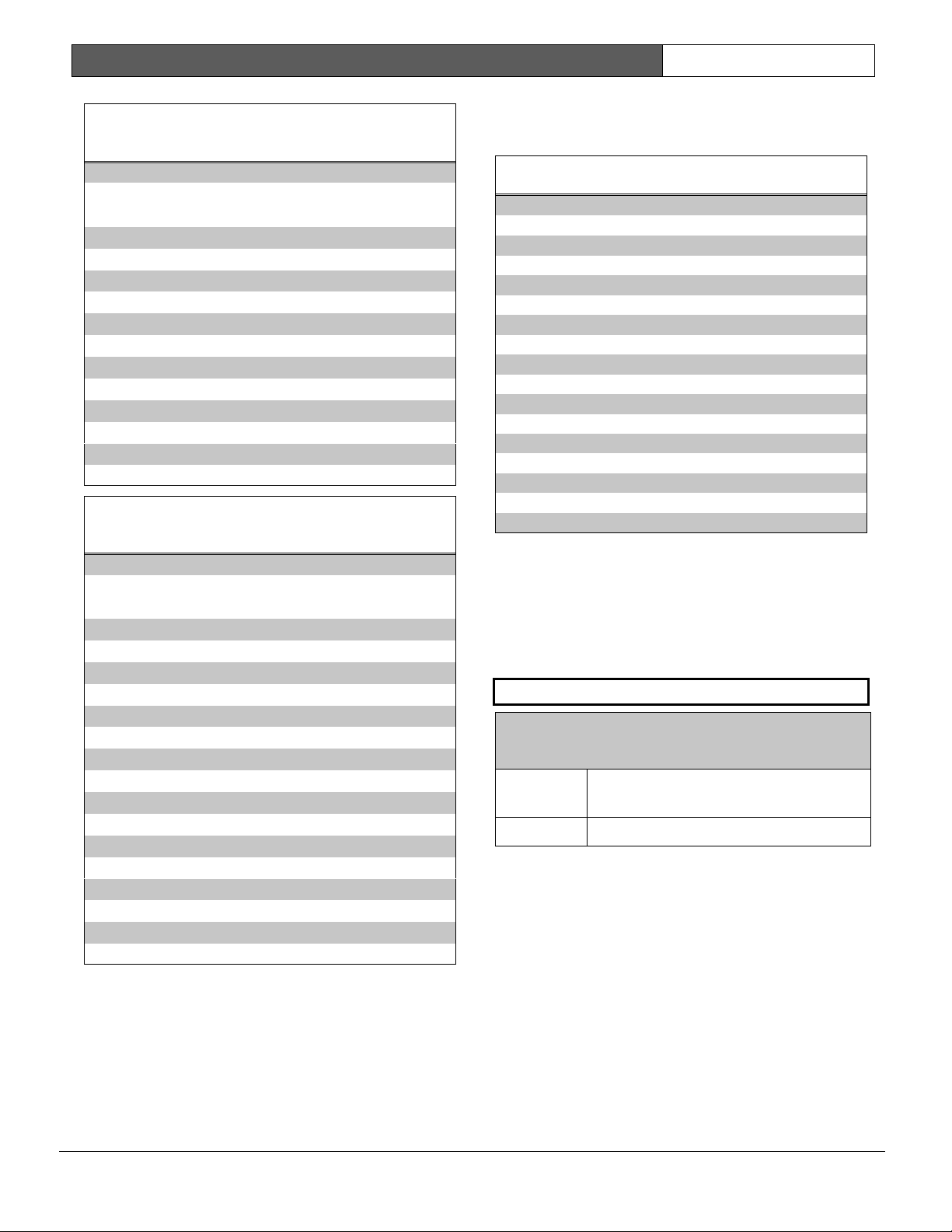
1.5 Product Handlers
Programming the 9000 Series requires multiple product handlers. The availability of each handler is indicated in
Table 4. See the control panel specific Release Notes to determine the most up-to-date handler versions.
Although the handlers shown in Table 4 can be used to program any of the new control panels, not all of the
functions operate. For example, the RADXUSR1 Handler is used to program users 000 through 124. Even though
the handler allows you to program users 100 through 124, the D7412G does not allow the activation of these
users.
Table 4: Product Handlers
Product Handler Function D9412G D7412G
9000MAIN
Covers Panel-Wide, Area, Command Center Function List, User
Interface, and Relay programming modules.
RADXUSR1 Covers Passcode/Token programming for Users 000 through 124
(99 users for the D7412G).
RADXUSR2 Covers Passcode/Token programming for Users 125 through 249.
N/A
RADXPNTS Covers Point Index and Point Assignment programming for all points.
RADXSKED Covers Open/Close Windows, User Access Windows, Skeds, and
Holiday Index programming modules.
RADXAUX1 Covers SDI Automation, SDI RAM Parameters, Enhanced
Communication Parameters, Route Group Attempts, Miscellaneous,
and Cross Point Parameters.
RADXAXS
Covers the programming parameters for installed D9210B Door
Controllers. The Program Entry Guide and Program Record Sheet for
this handler comes with the D9210B Access Control Module.
1.6 Programming Options
This Program Entry Guide is set up in a specific order.
Related program entries are grouped together in
modules as they appear in the specific product
handlers. The handler and the programming module
are listed at the top of each page to help you find
specific programming prompts.
This Program Entry Guide shows the programming
options for each product handler. Each option is
listed with:
• The Program Item Prompt: Each prompt is
shown, as it appears in the D5200 Programmer
[see the D5200 Programmer Operations Manual
(P/N: 74-06176-000)] or the Remote Account
Manager [see the RPS Operations Manual (P/N:
38849)]. Sometimes, for space considerations, a
prompt must be abbreviated in the Programmer
display. In these cases, the meaning of the
prompt is explained below the prompt
• Program Entry Default Setting: Because
defaults are set for the typical installation, you
may not need to program each prompt. Review
the default entries in the Program Record Sheet
shipped with the control panel to determine
which prompts must be programmed.
• Program Entry Selections: Only the selections
listed can be used for a particular program item.
The programmer does not accept inappropriate
entries.
• Program Entry Description: Provides concise
information regarding what can occur with the
various entry selections. Read the descriptions
carefully to avoid improperly programmed
equipment.
• Custom Programming: A new feature of the
D5200 Programmer is the option to select
custom programming (Yes or No) to expand
programming modules within the D5200.
Programming Custom as Yes does not affect a
parameter’s programming. It allows parameters
for special applications to be visible in the
programmer.
D9412G/D7412G | Program Entry Guide | 1.0 Introduction EN | 9
Bosch Security Systems | 1/04 | 47775E
1.7 Programming the Control Panel
with the D5200 Programmer
Latch the jumper in the upper right hand corner of
the control panel labeled as RESET on the PCB and
Reset Pin on the faceplate.
Connect the molex end of the cord to the connector
labeled PROG on the PCB and PROG CONN on
the faceplate.
Always initiate a control panel copy at the
NEWRECORD or FILENAME display when pressing
the [RECV] (copy) key of the D5200.
Always initiate a control panel load at the
FILENAME
prompt or set as factory default at the
NEWRECORD
prompt when pressing the [SEND]
(load) key.
Disconnect the D5200 before releasing the reset pin.
Do not leave the D5200 connected to the
PROG connector without latching the
RESET pin. Doing so causes SDI ##
TROUBLE and CALL FOR SERVICE to
display on the command centers. Door
controllers also activate depending upon
the SDI failure DIP switch setting.
Table 5: Programming Error Displays
Display Description
INCOMPATIBLE PANEL
You are connected to the
wrong control panel or
using the wrong handler.
Check the faceplate for the
model number and the
handler title.
CHECK CORD/RESET
PIN
Check the cord and reset
pin
0101
0101
0101
There is a 5 second to 25 second pause
after the reset pin is unlatched during
which the control panel scans all the
points and properly displays, logs, and
reports them.

D9412G/D7412G | Program Entry Guide | 1.0 Introduction EN | 10
Bosch Security Systems | 1/04 | 47775E
Notes:
D9412G/D7412G | Program Entry Guide | 2.0 9000MAIN EN | 11
Bosch Security Systems | 1/04 | 47775E
2.0 9000MAIN
Use this programming module to define the
operating characteristics that affect panel-wide
functions. There are nine programming categories in
this module: Phone, Phone Parameters, Routing,
Enhanced Communications, Area Parameters,
Command Center, User Interface, Function List, and
Relay Parameters.
2.1 Phone
The control panel can dial up to four different
telephone numbers when sending event reports. All
telephone numbers use the same receiver format.
Event report routing and communication protocols
are discussed in Section 2.3 Routing.
Phone 1
Default: Blank
Selection:
Up to 24 characters (do not enter
[SPACE])
0 to 9 Numbers 0 through 9
C 3-second pause
D 7-second dial-tone detect.
# or * Used for the same purpose as pressing
this key on a telephone keypad when
manually dialing. For example, an
asterisk (*) may be needed to access
your long distance service. Do not use
these characters when pulse dialing.
Blank Control panel dials no phone number.
Programming this item Blank does not
disable phone routing. To disable
reporting to this phone, see Section 2.3
Routing.
This is the telephone number the control panel dials
to contact the central station receiver when sending
event reports. This number is Phone 1 referred to in
the prompts in Section 2.3 Routing.
The control panel is pre-programmed with a
7-second dial tone detect period. When a dial tone is
detected or the waiting period ends, the control
panel begins to dial. To extend the dial tone detect
period, place a D before the phone number. To
insert a pause during or after dialing, use C in the
number sequence. For example, if the control panel
hangs up before it hears the Modem IIIa
2
Ack tone
from the D6500/D6600, program extra Cs after the
phone number. The control panel waits on line for
three extra seconds for each C programmed.
Enter up to 24 of the following characters to define
dialing characteristics.
0101
0101
0101
Using both phone data entry lines: The first
line of the phone number data entry line
must be filled (twelve characters) before
you press [ENTER] to move on to the
second line. If you enter characters on the
second line, and there are less than twelve
characters on the first line, the second line
clears when you press [ENTER].
Phone 2
Default: Blank
Selection:
Up to 24 characters (do not enter
[SPACE])
See explanation of
Phone 1
. This number is Phone
2, referred to in the prompts in Section 2.3 Routing.
Phone 3
Default: Blank
Selection:
Up to 24 characters (do not enter
[SPACE])
See explanation of
Phone 1
. This number is Phone
3, referred to in the prompts in Section 2.3 Routing.
Phone 4
Default: Blank
Selection:
Up to 24 characters (do not enter
[SPACE])
See explanation of
Phone 1
. This number is Phone
4, referred to in the prompts in Section 2.3 Routing.
D9412G/D7412G | Program Entry Guide | 2.0 9000MAIN EN | 12
Bosch Security Systems | 1/04 | 47775E
2.2 Phone Parameters
The program items in this category describe panel-
wide characteristics for telephone dialing, receiver
format, and supervision.
Modem Format
Default: Yes
Selection:
Yes or No
Yes
Radionics’ Modem IIIa
2
Communication Format: Reports
identify points as 001 through 247 and
passcode User ID codes as 000 through
249 at the D6500/D6600 Receiver
(unless
Point/User Flag
is
programmed Yes; see the
Point/User
Flag
prompt in this section). When
reporting point events, Radionics’
Modem IIIa
2
Communication Format
also sends point text to the
D6500/D6600 as programmed in Point
Assignments.
No
BFSK (2300 Hz or 1400 Hz
acknowledgment tone).
Central Station Receiver Format for
Transmission of Reports: Modem format provides
many reporting advantages over the BFSK format.
See the D6500/D6600 Report Directory for more
information about the effect of reporting formats.
Modem Format must be set to Yes when
sending events over a network to a D6600
receiver (NetCom).
0101
0101
0101
If Modem Format is No, be sure to assign
a number to identify Duress Reports in
BFSK Duress Code in this programming
section.
Point/User Flag
Default: Yes
Selection:
Yes or No
Yes The control panel sends a flag with
each report telling the D6500/D6600 to
convert point numbers and User ID
numbers to COMEX format. The
conversions are shown in Table 6 and
Table 7. No matter how the
D6500/D6600 is programmed for
output to the computer system, points
and User ID numbers are converted
when this item is Yes. (See the D6600
Communications Receiver/Gateway
Computer Interface Manual, Appendix C,
Numbered Table and Note 1.)
No The control panel does not send the
flag. The D6500/D6600 outputs point
numbers as 001 to 247 (rather than 100
to 732) and User ID numbers as 000 to
249 (rather than 000 to F08), as
indicated in Table 6 and Table 7.
This program item determines how point and User
ID numbers are presented at the D6500/D6600
display, printer, and computer RS-232 output.
When
Modem Format
is Yes, the control panel
sends expanded Radionics’ Modem IIIa
2
Communication Format reports to the
D6500/D6600. If your central station data files are
not set up for point and User ID number reporting,
you can use this program item to convert these
numbers to COMEX Reports.
When
Modem Format
is Yes, the control panel
sends expanded Radionics’ Modem IIIa
2
Communication Format Reports to the receiver.
Point/User Flag
affects Radionics’ Modem IIIa
2
Communication Format data as shown in Table 6.
The Bosch Security Systems D6500/D6600 Receiver
adds the leading zero in the User ID number with
Point/User Flag
programmed No.
D9412G/D7412G | Program Entry Guide | 2.0 9000MAIN EN | 13
Bosch Security Systems | 1/04 | 47775E
Table 6: Modem IIIa
2
Communication Format
Data - User ID Numbers
Point/User Flag
NO
Point/User Flag
YES
000 000
001 to 005 001 to 005
006 to 013 601 to 608
014 to 021 701 to 708
022 to 029 801 to 808
030 to 037 B01 to B08
038 to 045 C01 to C08
046 to 053 D01 to D08
054 to 061 E01 to E08
062 to 069 F01 to F08
070 to 249 000
Table 7: Modem IIIa
2
Communication Format
Data – Point Numbers
Point/User Flag
NO
Point/User Flag
YES
001 to 008 100 to 800
009 to 024 101 to 116
025 to 040 201 to 216
041 to 056 301 to 316
057 to 072 401 to 416
073 to 088 501 to 516
089 to 104 601 to 616
105 to 120 701 to 716
121 to 136 801 to 816
153 to 168 217 to 232
169 to 184 317 to 332
185 to 200 417 to 432
201 to 216 517 to 532
217 to 232 617 to 632
233 – 247 717 to 731
Independent Zone Control Notice: When using
Independent Zone Controls (IZC) to send
Opening/Closing Reports by point, do not duplicate
reporting independent point numbers with User ID
Reports (see Section 3.1 Passcode/Token Worksheet). For
example: If an IZC is connected to Point 8, User ID
8 should not be used.
D6000: Opening/Closing User ID numbers are
identified at the receiver as ZONEs (same
identification as independent points).
Table 8: Zones
User ID Number Zone
1 B
2C
3 D
4E
5 F
66
7 7
88
91 1
92 2
93 3
94 4
95 5
96 0
D6500/D6600 Receiving BFSK Format:
Opening/closing User ID numbers are identified at
the receiver as ZN (same identification as
independent points). The ZN numbers are based on
the tens digit of the User ID number. This only
applies for Users 000 through 099. Users 100
through 249 do not report in BFSK format.
DTMF Dialing
Default: Yes
Selection:
Yes or No
Yes Dials the programmed phone
number(s) using DTMF.
No Pulse dialing only.
Use dual-tone multi-frequency (DTMF) to dial the
central station receiver phone number(s) for event
reports, and/or the RPS.
D9412G/D7412G | Program Entry Guide | 2.0 9000MAIN EN | 14
Bosch Security Systems | 1/04 | 47775E
Phone Supv Time
Default: Blank
Selection:
Blank or 10 to 240
Blank No phone line supervision.
10 to 240 Enter the number of seconds (in 10
second increments) you wish to
supervise the phone line. After a faulted
phone line restores, it takes the same
amount of time to initiate restoral
responses.
Phone line trouble responses: Command centers
display SERVC PH LINE # to indicate which
phone line failed. The command center initiates a
trouble tone if
Buzz on Fail
is Yes and
CC Trouble
Tone
is Yes.
With dual phone lines (using the D928 Module), the
restored phone line handles all messages regardless
of the phone line’s number.
Phone, Trouble, and Restoral Events report when
they occur. They report also when a Diagnostic
Report is initiated from a command center or by a
Sked.
Alarm On Fail
Default: No
Selection:
Yes or No
Yes Generate alarm responses when a
phone line fails.
No Phone failures report as trouble
responses for Area 1 and/or the
account number for Area 1.
0101
0101
0101
Phone Supv Time must be programmed to
use this feature.
Phone Failure Alarm Responses: The
Alarm Bell relay for Area 1 activates. All
Phone Event messages report as Area 1
and/or the account number for Area 1.
Buzz on Fail
Default: No
Selection:
Yes or No
Yes Generate panel-wide trouble tones and
display PHONE FAIL # at command
centers when a Phone Fail Event
occurs.
No Does not generate trouble tones at
command centers when a Phone Fail
Event occurs. PHONE FAIL # still
displays.
0101
0101
0101
Phone Supv Time must be programmed to
use this feature.
De-selecting individual command
centers for panel-wide trouble tones:
Panel-wide trouble tones for programming
CC can turn off individual command
centers (based on their CC # 1 through 8)
# Trouble Tone in Command Center
Parameters as No.
Two Phone Lines
Default: No
Selection:
Yes or No
Yes The D928 Dual Phone Line Module is
installed. The LEDs on the D928 light
to indicate primary or secondary line
trouble and COMM FAIL.
No No D928 Dual Phone Line Module.
Use this program item when a D928 Dual Phone
Line Module is connected to the control panel. Both
lines must operate the same; either ground start or
loop start.
0101
0101
0101
IMPORTANT! Program Phone Supv Time
when using two phone lines.
NFPA standards prohibit the use of ground
start phone lines in systems monitoring
Fire points.
D9412G/D7412G | Program Entry Guide | 2.0 9000MAIN EN | 15
Bosch Security Systems | 1/04 | 47775E
BFSK Duress Code
Default: 0
Selection:
0 to 9
If Duress Enable in Area Parameters is Yes and
Modem Format
in Phone Parameters is No, you
must program a number to identify Duress Reports
at the central station.
Expand Test Rpt
Default: No
Selection:
Yes or No
Yes Report events listed in Routing Group
Test Reports report to the central
station if they are off-normal.
No Does not report off-normal conditions
for the events listed in the Routing
Group Test Reports at test time.
Use this program item to add system event
information to scheduled Test Reports. Test Reports
are set up as scheduled events. See Section 5.2 Skeds.
This parameter is related only to Sked
Function Code 9 (Test Report) and
whether this Sked transmits Expanded
Test Report information or not. It does not
have any bearing on Sked Function Codes
28 (Expanded Off-Normal Test Report)
and 29 (Non-Expanded Off-Normal Test
Report).
Ground Start
Default: Long
Selection:
Long or Short
Long Standard duration of ground. Use this
setting for most ground start telephone
systems. The duration is 700
milliseconds.
Short Shorter duration of ground. Use this
setting for telephone systems where
specified. The duration is 250
milliseconds.
Some newer ground start telephone exchange
switches require a shorter amount of time to initiate
dial tone. If the control panel cannot initiate a dial
tone on the ground start line with the default (long)
setting, try the short setting.
Press the [SPACE] bar to scroll through the
selections. Press [ENTER] when the correct selection
appears in the display.
Use this program item only when the control
panel is connected to ground start
telephone lines. Ground start is not allowed
on UL Listed systems.
2.3 Routing
Use routing to select full or partial groups of events
which report to up to four different destinations.
Routing includes choosing the most important
destination (route number), the events reported to a
single or multiple destination, and if the events fail,
selecting a backup destination.
2.3.1 Called Party Disconnect
Telephone companies provide called party
disconnect to allow the called party to terminate a
call. The called party must go on hook (hang up) for
a fixed interval before a dial tone is available for a
new call. This interval varies with telephone
company equipment. D9412G/D7412G firmware
allows for called party disconnect by adding a 35
second on hook interval to the dial tone detect
function. If the control panel does not detect a dial
tone in 7 seconds, it puts the phone line on hook for
35 seconds to activate called party disconnect, goes
off hook and begins a 7-second dial tone detect. If
no dial tone is detected, the control panel dials the
number anyway. Each time the number is dialed,
the control panel records this as an attempt. After
ten attempts, the control panel goes into
communications failure and Comm Fail Route #
displays on the command centers.
2.3.2 Route Number Groups: Which Has the
Highest Priority?
To program a group, first choose a route number.
The lower the route number, the higher priority that
group has (for example, events reported for Route 1
have a higher priority than Routes 2, 3, or 4 if each
group tries to send a message at the same time). This
becomes important when programming duplicate
reports or choosing the events you want to ensure
report first regardless of the number of events that
need to report to multiple groups. Route 1 group
primary device is the first destination the control
panel attempts to dial if an event in that group must
be reported. If the control panel is idle, any event
generated for any group initiates a dialing sequence.
D9412G/D7412G | Program Entry Guide | 2.0 9000MAIN EN | 16
Bosch Security Systems | 1/04 | 47775E
2.3.3 Programming a Primary and Backup
Destination
Each route number has an
R# Primary Device
and
an
R# Backup Device
. In typical applications
where two phone numbers are programmed, the
R#
Primary Device
destination is the phone number
the route group attempts to dial first. If the
R#
Primary Device
destination fails to connect to the
central station receiver after two dialing attempts, the
R# Backup Device
destination is dialed. In
addition, the control panel can be programmed so
the
R# Primary Device
and/or the
R# Backup
Device
can be an SDI device, such as a D9133TTL-
E Network Interface Module. The control panel can
also be programmed to make only one attempt for
the
R# Primary Device
before attempting to send
events using the
R# Backup Device
.
2.3.4 Enhanced Routing
In previous versions, only Phone numbers 1 through
4 could be programmed for the Primary and Backup
Destinations. The D9412G/D7412G allow events to
be transmitted to up to four additional SDI Paths.
The D9133TTL-E Network Interface Module (with
Ethernet) connects directly to the SDI Bus and
occupies SDI Address 88. For additional information
regarding the specific programming requirements for
enhanced communications, see Sections 2.4 Enhanced
Routing and 6.5 Enhanced Communications.
2.3.5 Programming a Duplicate Report
To allow an event within a group to report to
multiple groups, the event should be Yes for each
route number available. For instance, programming
Fire Alarms for Route Group 1 and Route Group 2
results in the fire alarms first reporting to Route
Group 1 followed by a duplicate report to Route
Group 2.
2.3.6 Routing Destination Communication
Failures
When the
R# Primary Device
fails to connect with
the central station after one or two attempts (see
RG# 1 Attempt in
Sectio
n
6.6.1
Route Group
Attempts), the
R# Backup Device
phone number or
SDI Path is attempted. The central station receives
the original event with a COMM FAIL PHONE# =
(1, 2, 3, or 4) if the
R# Primary Device
destination
is a phone number. If the
R# Primary Device
is an
SDI Path, the central station receives the original
event with A COMM FAIL RG# SDI## (SDI Path
1 = 88, SDI Path 2 = 89, SDI Path 3 = 90, SDI Path
4 = 91). When all attempts to both the
R# Primary
Device
and
R# Backup Device
fail, a Comm Fail
RG# Event is generated. Comm Restore Events are
not generated.
2.3.7 Message Prioritization within a Route
Number
The D9412G/D7412G Control Panels meet the
digital reporting requirements for UL 864. Fire
Alarm Events have the highest priority and are
reported first for each group. The next highest
priority events are in the following order: panic,
duress, medical, intrusion alarm, supervisory, and all
troubles and restorals.
0101
0101
0101
To comply with NFPA and UL864, you
must program Route 1 to report only Fire
Alarm Events to ensure the fastest
reporting time.
2.3.8 Dialing Attempts
The D9412G/D7412G Control Panels have a
prompt called
RG# 1 Attempt
(see Section
6.6.1
Route Group Attempts.).
If this item is set to No, the control panel first makes
up to six attempts to make contact using the primary
device within a route group. If unsuccessful, it makes
up to four attempts to make contact using the
backup device before initiating a Comm Fail Report.
When only one destination is programmed, the
control panel makes ten attempts to contact that
destination. Each group takes approximately 10
minutes to go into Comm Fail.
If this item is set to Yes, the control panel only
makes one attempt (instead of two) to contact the
primary device before attempting to contact the
backup device. The route group still makes a total of
ten attempts; however, the
R# Primary Device
makes five attempts and then the
R# Backup
Device
makes five attempts.
D9412G/D7412G | Program Entry Guide | 2.0 9000MAIN EN | 17
Bosch Security Systems | 1/04 | 47775E
Route #
Default: 1
Selection:
1 to 4
1 First group sent
2 Second group sent
3 Third group sent
4 Fourth group sent
Enter the number specifying the route group to
program. The route represents the group you wish to
send a group of reports. The groups are prioritized. 1
is the first group to report and 4 is the last group to
report. Each group has a primary and a backup
device. The primary device is the first (most
important) destination used to reach the
programmed route within this group. The backup
device is used if the primary device fails.
R# Primary Device
Default: Blank
Selection:
Blank, 1 to 4
1 Phone 1 or SDI Path 1 is this group’s
primary destination.
2 Phone 2 or SDI Path 2 is this group’s
primary destination.
3 Phone 3 or SDI Path 3 is this group’s
primary destination.
4 Phone 4 or SDI Path 4 is this group’s
primary destination.
Enter the number specifying the primary device.
R# Backup Device
Default: Blank
Selection:
Blank, 1 to 4
1 Phone 1 or SDI Path 1 is this group’s
backup destination if the primary
destination fails.
2
Phone 2 or SDI Path 2 is this group’s
backup destination if the primary
destination fails.
3 Phone 3 or SDI Path 3 is this group’s
backup destination if the primary
destination fails.
4 Phone 4 or SDI Path 4 is this group’s
backup destination if the primary
destination fails.
Enter the number specifying the backup device. The
backup device is used when the primary device fails
to reach the programmed destination.
View Events?
Default: No
Selection:
Yes or No
Yes
Access each routing group and
program individual events for this
route group only (D5200).
No
Continue programming without
viewing individual groups.
The D5200 Programmer reveals the following sub-
prompts. Leaving
View Events?
as No allows the
user to ignore a large area of programming that
might not need to be changed.
D9412G/D7412G | Program Entry Guide | 2.0 9000MAIN EN | 18
Bosch Security Systems | 1/04 | 47775E
Fire Reports
Selecting Yes enables a report to be sent when the
event occurs.
Table 9: Diagnostic Reports
Report Selections Description
R# Fire Alarm
Yes, No
Reports Fire Event.
R# Fire Restore
(Alarm)
Yes, No
Reports fire restoral
from alarm.
R# Fire Missing
Yes, No
Reports missing Fire
point.
R# Fire Trouble
Yes, No
Reports fire trouble.
R# Fire
Supervis
Yes, No
Reports fire
supervision.
R# Fire Restore
(T/M/S)
Yes, No
Reports fire restoral
from trouble,
missing, or bypass.
R# Fire Cancel
Yes, No
Reports canceled
fire alarm.
R# Fire Sup
Miss
Yes, No
Report fire
supervisory missing.
R# Fire Supv
Rest
*
Yes, No
Reports restorals
from Fire
Supervision.
* This event is not reported when using BFSK format.
Burglar Reports
Selecting Yes enables sending a report when the
event occurs.
Table 10: Burglar Reports
Report Selections Description
R# Alarm
Yes, No
Report Burglar Alarm
Event.
R# Burg
Restore
Yes, No
Reports non-fire
restoral from trouble,
missing, or
supervisory.
R# Duress
Yes, No
Duress Report.
R# Missing
Alarm
Yes, No
Reports missing
Alarm point.
R# Usr Code
Tmpr
Yes, No
Reports user code
tamper.
R# Trouble Rpt
Yes, No
Reports Trouble
Event.
R# Missing Trbl
Yes, No
Reports Missing
Trouble Event.
R# Non Fire
Suprv
Yes, No
Reports Non-fire
Supervision Event.
R# Pt Bus Fail
Yes, No
Reports point bus
failure.
R# Pt Bus Rstl
Yes, No
Reports restoral of
point bus after failure.
R# Non Fire
Cncl
Yes, No
Reports canceled
non-fire alarm.
R# Alarm
Restore
Yes, No
Reports non-fire
restoral from alarm.
R# Sup Missing
Yes, No
Reports supervisory
missing.
R# Unverfied
Evt
†*
Yes, No
Reports Unverified
Events for Cross
points.
†
This event is not reported when using BFSK format.
* This event does not produce a corresponding Restoral
Event.
0101
0101
0101
The Unverified Event is transmitted when a
single point programmed in Cross Point
Group faults into an alarm condition then
restores before the Cross Point Time
elapses. This event encompasses both
Fire and Non-fire points. It is not, however,
related to the Verify Time used for smoke
detectors.
D9412G/D7412G | Program Entry Guide | 2.0 9000MAIN EN | 19
Bosch Security Systems | 1/04 | 47775E
Restoral Reports are not sent if the
control panel is reset after a point is
bypassed and then the point is
unbypassed. This is true for both Fire and
Non-fire points.
The 9000 Series Control Panels log a
Ground Fault Event as Trouble Point 256.
User Reports
Selecting Yes enables a report to be sent when the
event occurs.
Table 11: User Reports
Report Selections Description
R# Point
Bypass
Yes, No
Reports Point
Bypass Event.
R# Forced
Point
Yes, No
Reports Forced
Point Event.
R# Point Open
Yes, No
Reports Point
Opening Event.
R# Point Close
Yes, No
Reports Point
Closing Event.
R# Forced Arm
Yes, No
Reports point forced
armed.
R# Fail To
Open
Yes, No
Reports Fail to
Open Event.
R# Fail To
Close
Yes, No
Reports Fail to
Close Event.
R# Ext Clos Tm
Yes, No
Reports Extend
Close Time Event.
R# Opening
Rpt
Yes, No
Reports Opening
Events.
R# Forced
Close
Yes, No
Reports Point
Forced Close Event
R# Closing Rpt
Yes, No
Reports Closing
Events.
R# FC Perim
Inst
Yes, No
Reports Forced
Close Perimeter
Instant Armed Event.
R# FC Perim
Delay
Yes, No
Reports Forced
Close Perimeter
Delay Armed Event.
R# Perim Inst
Arm
Yes, No
Reports Perimeter
Instant Armed Event.
R# Perim Delay
Arm
Yes, No
Reports Perimeter
Delay Armed Event.
R# Send User
Text
Yes, No
Reports user text.
D9412G/D7412G | Program Entry Guide | 2.0 9000MAIN EN | 20
Bosch Security Systems | 1/04 | 47775E
Test Reports
0101
0101
0101
To send a single Test Report (R# Test
Report), enable Sked Function Code #9
(Test Report) in the Skeds section of the
program.
To expand this Test Report to include any
off-normal point condition or other off-
normal conditions of events listed in Diag
Reports as a Non-status Event following a
Test Report, Expand Test Rpt in Section
2.2 Phone Parameters must be
programmed Yes.
Events R# Log Threshold, R# Log
Overflow, and R# RAM Fail are added to
the reports sent with Expanded Test
Reports if they are enabled in RAM Reports
and Expand Test Rpt is also enabled.
To initiate a Status Report, which includes
all R# S: ____ Events as a Status Event (as
opposed to a Non-status Event), Sked
Function Code #10 must be enabled in the
Skeds section of the program.
Reporting off-normal conditions as a Status
Report following a Test Report is required
by some automation systems. Reporting off-
normal conditions as a Non-status Report,
which follows a Test Report, is required for
other automation systems.
An off-normal condition is any point which is
missing, trouble, supervisory, or in alarm (as
opposed to normal). Also, points not
cleared at the command center report as
off-normal.
Control Panels with Firmware version 6.30
or higher can generate an Expanded Off-
Normal Test Report by using Sked Function
Code 28 or a Non-Expanded Off-Normal
Test Report using Sked Function Code 29.
To generate this event, one or more points
must be in an off-normal state at the time
the Sked executes. Expanded Off-Normal
Test Reports include the Off Normal Test
Report Event as well as events for any
points that are in an off-normal state at the
time the report is generated. Non-Expanded
Off-Normal Test Report Events are only
sent when a point is in the off-normal state
but only sends the Off Normal Test Report
Event.
Table 12: Test Reports
Report Selections Description
R# S: Alarm
Yes, No
Status Alarm Report
R# S: Trouble
Yes, No
Status Trouble
Report
R# S:
Supervised
Yes, No
Status Supervised
Report
R# Status
Report
Yes, No
Status Report
R# S: Open
Yes, No
Status Open Report
R# S: Close
Yes, No
Status Close Report
R# Test Report
Yes, No
Test Report
R# S: Perim
Inst
Yes, No
Status Perimeter
Instant Arm Report
R# S: Perim
Delay
Yes, No
Status Perimeter
Delay Arm Report
R# S: Fire Supv
Yes, No
Status Fire
Supervision Report
R# S: Fire
Alarm
Yes, No
Status Fire Alarm
Report
R# S: Fire Trbl
Yes, No
Status Fire Trouble
Report
R# S: Msng
Fire
Yes, No
Status Fire Missing
Report
R# S:
MsngBurgTr
Yes, No
Status Burg Missing
Trouble Report
R# S:
MsngBurgAl
Yes, No
Status Burg Missing
Alarm Report
R# S:
FireSpMsng
Yes, No
Status Fire
Supervision Missing
Report
R# S:
SuperMsng
Yes, No
Status Non-fire
Supervision Missing
Report
R# S:
DrLeftOpen
Yes, No
Status Door Left
Open Report
Diag Reports
Selecting Yes enables sending a report when the
event occurs. If the off-normal state of the following
events (indicated with an *) still exist, they report
when a Test Report (see the
Test Reports
sub-
prompt in Section 2.3.8 Dialing Attempts) is initiated
and Expanded Test Rpt is programmed Yes.
D9412G/D7412G | Program Entry Guide | 2.0 9000MAIN EN | 21
Bosch Security Systems | 1/04 | 47775E
Table 13: Diagnostic Reports
Report Selections Description
R# SDI Dev Fail*
Yes, No
Reports SDI device
failure.
R# SDI Dev Restl
Yes, No
Reports restoral of SDI
device failure.
R# Watchdog
Rset
Yes, No
Reports Watchdog
Reset Event.
R#
ParaChksmFail
Yes, No
Reports parameter
checksum failure.
R# Reboot
Yes, No
Reports Reboot Event.
R# Ph Line Fail*
Yes, No
Reports failure of phone
line.
R# Ph Line Rstl
Yes, No
Reports restoral of
phone line after failure.
R# AC Fail*
Yes, No
Reports failure of AC
power to control panel.
R# AC Restorl
Yes, No
Reports restoral of AC
power to control panel
after failure.
R# Batt Missing*
Yes, No
Reports Battery Missing
Detection Event.
R# Battery Low*
Yes, No
Reports low battery
power.
R# Battery Rstl
Yes, No
Reports restoral of
battery power to control
panel after Missing or
Low Event.
R# Rt Comm
Fail*
1
Yes, No
Reports failure to send
report to specific route.
R# Rt Comm Rstl
Yes, No
Reports restoral of
communication to
specific route after a
failure.
R# Checksum
Fail
Yes, No
Reports Checksum Fail
Event.
R# Network Fail
2
Yes, No
Reports failure of
network.
R# Network
Rest
2
Yes, No
Reports restoral of
network.
R# Network
Cond
2
Yes, No
Reports condition of
network.
1
This event covers Comm Fail Route Group and Comm
Fail Phone. If enabled, both events are sent; if disabled,
neither event is sent.
2
This event reserved for future use.
0101
0101
0101
Only turn on Rt Comm Fail and Rt Comm
Restore in one route group.
Relay Reports
Selecting Yes enables sending a report when the
event occurs.
Table 14: Relay Reports
Report Selections Description
R# Sensor
Reset
Yes, No
Reports Sensor
Reset Event.
R# Relay Set
Yes, No
Reports Relay
Set Event.
R# Relay Reset
Yes, No
Reports Relay
Reset Event.
When activating an on-board relay using
PC9000, the 9000 Series Control Panel
logs and prints the event as Relay 250
(Relay A), Relay 251 (Relay B), and Relay
252 (Relay C).
AutoFunc Reports
The following prompts support customized routing
of Auto Function Reports. Selecting Yes enables a
report to be sent when the event occurs.
Table 15: Auto-Function Reports
Report Selections Description
R# Sked
Executed
Yes, No
Reports Sked
Executed Event.
R# Sked
Changed
Yes, No
Reports Sked
Changed Event.
R# Execute Fail
Yes, No
Reports a Fail to
Execute Event.
D9412G/D7412G | Program Entry Guide | 2.0 9000MAIN EN | 22
Bosch Security Systems | 1/04 | 47775E
RAM Reports
Selecting Yes enables sending a report when the
RAM Passcode Event occurs.
RAM Access Fail can indicate a
wrong RAM passcode when
communicating with the control panel, or a
valid RAM session was terminated by a
means other than a Good-bye or Reset-
bye command. Remote Reset indicates
a Reset-bye command issued from RAM,
Bad Call to RAM indicates the control
panel called RAM but was unable to
connect.
Table 16: RAM Reports
Report
Selection
s
Description
R# Log
Threshold
Yes, No
Reports Event log
threshold reached.
R# Log
Overflow
Yes, No
Reports Log is full,
old events are
overwritten.
R# Para
Changed
Yes, No
Reports RAM
Parameter Change
Event.
R# RAM OK
Yes, No
Reports Successful
RAM Access Event.
R# RAM Fail
Yes, No
Reports Failed
Access RAM Event.
R# Remote
Reset
Yes, No
Reports Remote
Reset Event.
R# Program
OK
Yes, No
Reports Successful
Laptop Access
Event.
R# Program
Fail
Yes, No
Reports Failed
Laptop Access
Event.
Point Reports
Selecting Yes enables a report to be sent when the
event occurs.
Table 17: Point Reports
Report Selections Description
R# Service
Start
Yes, No
Reports Service
Walk Test Start
Event.
R# Service End
Yes, No
Reports Service
Walk Test End
Event.
R# Fire Walk St
Yes, No
Reports Fire Walk
Start event.
R# Fire Walk
End
Yes, No
Reports Fire Walk
End Event.
R# Walk Test
St
Yes, No
Reports Walk Test
Start Event for Walk
Test and Invisible
Walk Test.
R# Walk Test
End
Yes, No
Reports Walk Test
End Event for Walk
Test and Invisible
Walk Test.
R# Extra Point
Yes, No
Reports Extra Point
Event.
R# Send Point
Text*
Yes, No
Reports point text.
R# RF Low Bat
Yes, No
Reports low battery
conditions for RF
points.
R# RF Low Bat
Res
Yes, No
Reports low battery
restoral conditions
for RF points.
* Point text is always transmitted when using
NetCom applications.
D9412G/D7412G | Program Entry Guide | 2.0 9000MAIN EN | 23
Bosch Security Systems | 1/04 | 47775E
User Chng Reports
Selecting Yes enables a report to be sent when the
event occurs.
Table 18: User Change Reports
Report Selections Description
R# Date
Changed
Yes, No
Reports Date
Change Event.
R# Time
Changed
Yes, No
Reports Time
Change Event.
R# Delete
User*
Yes, No
Reports Delete User
Code Event.
R# User Code
Chg
Yes, No
Reports User
Passcode Add or
Change Event.
R# Area Watch
Yes, No
Reports area watch
start and watch end.
R# Card
Assigned
Yes, No
Reports Card
Assigned to User
Event.
R# Change
Level
Yes, No
Reports Access
Control Level
Change Event.
* With R# Delete User Events, the control panel
always uses the account number from Area 1.
Access Reports
Selecting Yes enables a report to be sent when the
event occurs.
Access Granted, No Entry, Request to
Enter (RTE) and Request to Exit (REX)
Events may be turned on or off by each
D9210B.
Table 19: Access Reports
Report Selections Description
R# Access
Granted
Yes, No
Reports Access
Granted Event.
R# No Entry
Yes, No
Reports No Entry
Event.
R# Door Lt
Open
Yes, No
Reports Door Left
Open Event.
R# Cycle
Door
Yes, No
Reports Open Door
Event.
R# Door
Unlocked
Yes, No
Reports Unlock Door
Event.
R# Door
Secure
Yes, No
Reports Secure Door
Event.
R# Door
Request
Yes, No
Reports RTE or REX
Event.
R# Door
Locked
Yes, No
Reports Locked Door
Event.
2.4 Enhanced Routing
Enhanced routing allows the control panels to
determine whether events are routed over standard
telephone lines and/or a local/wide area network
(LAN/WAN). To send events over a LAN/WAN, a
D9133TTL-E (SDI-Network Interface Module) is
required. Additionally, enhanced routing
enables/disables the control panel’s ability to send
events to a numeric pager. If the installation does
not require these applications, skip this section.
With enhanced routing, whether you use standard
telephone lines or the D9133TTL-E, you can select
full or partial groups of events to be reported to up
to four different destinations. Routing includes
choosing the most important destination, whether
events report to a single or multiple destinations, and
if the events fail, the backup destination used.
2.4.1 Programming a Primary and Backup
Destination
Each route number has an
R# Primary Device
and
an
R# Backup Device
. With the addition of
enhanced communications, the
R# Primary Device
destination can be either the phone number or the
path number IP address to which the route group
first attempts to send the event. If the
R# Primary
Device
destination fails to connect to the central
station receiver after one or two attempts (see also
RG# 1 Attempt
), the
R# Backup Device
destination is attempted.
D9412G/D7412G | Program Entry Guide | 2.0 9000MAIN EN | 24
Bosch Security Systems | 1/04 | 47775E
2.4.2 Programming a Duplicate Report
To allow an event within a group to report to
multiple groups, the event should be Yes for each
route number available. For instance, programming
Fire Alarms for Route Group 1 and Route Group 2
results in the fire alarms first reporting to Route
Group 1 followed by a duplicate report to Route
Group 2.
Section 2.4 Enhanced Routing determines the route
groups and which destinations within the route
groups use D9133TTL-E Modules for reporting
purposes. A single D9133TTL-E Module can be
used to transmit events to up to four different
destinations.
For example, if you want to send events using Route
Group 1 over a LAN/WAN as your primary
destination, and use a standard telephone line as
your backup destination, you must program the
following sections:
1. Routing (see Section 2.3 Routing)
a. Select Route Group 1
b. Program a 1 for Primary Destination
c. Program a 1 for Backup Destination
d. Enable all applicable events to be included
in Route Group 1.
Phone (see Section 2.1 Phone)
a. Select Phone 1.
b. Program Phone 1 with the applicable central
station receiver phone number.
Enhanced Routing (see Section 2.4 Enhanced Routing)
a. Enter Yes for Route Group 1 Primary SDI.
(Tells the control panel to send the events to
the D9133TTL-E using IP Address 1.)
b. Enter No for Route Group 1 Backup SDI.
(Tells the control panel to use the phone
line to send events if the primary destination
fails after one or two attempts.)
Because you are using an SDI Path to send events,
you must also program the applicable items in
Section 6.5 Enhanced Communications.
If you use a D9133TTL-E as a Primary
Device in any of the route groups, follow
these programming rules:
• Assign IP Address 1 as the Primary
Device in Route Group 1.
• Assign IP Address 2 as the Primary
Device in Route Group 2.
• Assign IP Address 3 as the Primary
Device in Route Group 3.
• Assign IP Address 4 as the Primary
Device in Route Group 4.
The backup device in any route group can
use any phone number or IP address
number.
If the External Modem feature is used,
RG# Primary SDI and RG# Backup SDI
must be set to No. The control panel
supports either enhanced communication
or external modem, but not both at the
same time.
RG# Primary SDI
Default: No
Selection:
Yes or No
Determines if the primary destination for Route
Group 1 (2, 3, or 4) is sent to the D913TTL-E.
RG# Backup SDI
Default: No
Selection:
Yes or No
This item determines if the backup destination for
Route Group 1 (2, 3, or 4) is sent to the D913TTL-E.
To completely disable Enhanced Routing
over an SDI path, RG#Primary SDI,
RG#Backup SDI, and Enhanced Comm
prompts must all be set to No.
The poll rate entry for the backup SDI path
might need to increase due to the amount
of traffic on the network and/or excessive
signals generated at once. Comm prompts
must all be set to No.
D9412G/D7412G | Program Entry Guide | 2.0 9000MAIN EN | 25
Bosch Security Systems | 1/04 | 47775E
RG# Primary Pager
Default: No
Selection:
Yes or No
Determines if this route group sends events to a
numeric pager. To send events to a numeric pager, a
phone number must also be programmed in the
route group’s primary destination.
0101
0101
0101
If programming the control panel to dial a
numeric pager, choose its route group
carefully. If there are any events to transmit
to a central station, be sure to place those
events in a lower numbered route group
class than the events that are in the route
group for the numeric pager.
Numeric Pager Capability
The D9412G/D7412G Control Panels can transmit
nearly any event to a numeric pager. Any time an
event is generated and routed to a numeric pager,
the control panel attempts to call the numeric pager
once for each message in the queue. To enable the
pager, program both the primary and backup phone
number to the numeric pager’s phone number in
any of the four route groups. Then select which
events are to be routed to the numeric pager within
the route group selected.
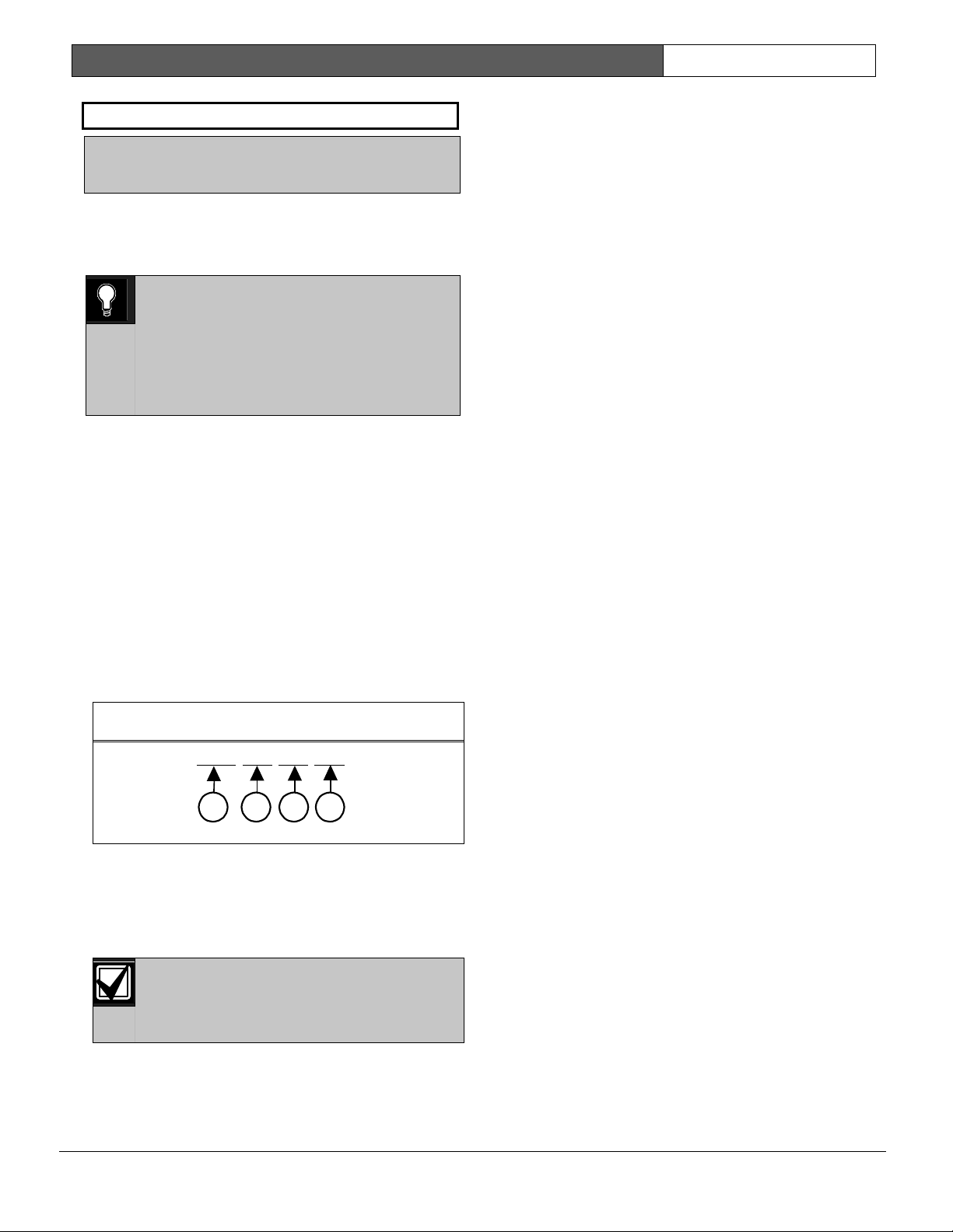
When events are sent to a numeric pager, up to four
fields can be displayed in the pager message. See
Figure 1.
Figure 1: Pager Display Fields
[
1234
-
001
-
011
-
008
]
1 - Account number (1234)
2 - Event policy (001)
3 - Event number (011, Fire Alarm Event)
4 - User number, point number, or relay number
(008)
The account number must contain four
numeric digits. No alpha characters (B to
F) are allowed when using the numeric
pager.
Programming the Pager Phone Number
To program the pager phone number, enter the
number used to reach the pager, followed by pauses.
Entering C creates a 3-second pause (example:
5552341CCC.)
Experiment with the number of pauses you add after
the page phone number. Each pause equals 3
seconds. Try calling the pager yourself first and
listening to the length of time it takes to get a beep
allowing you to enter touch-tone information. This
length is what you must program after the pager’s
phone number in Section 2.1 Phone. If you need a
longer pause, enter D after the number. Each D
equals to 7 seconds.
Using “#” characters in the phone number can affect
how the event is displayed on the pager:
• No “#” characters in phone number: Dashes
appear in the display [1234-001-011-008].
• One “#” character in phone number: Dashes
are replaced by zeros [1234000100110008].
• Two or more “#” characters in phone
number: Dashes appear in the display [1234-
001-011-008].
For example, if the phone number 2773074#CC
(seven-digit pager phone number followed by “#”
and two pauses) is programmed, the pager message
displays as follows: [1234000100110008] (dashes are
replaced by zeros).
If the “#” is not placed in the phone number, the
message displays as follows: [1234-001-011-008]
Also, a user may not want all four fields to be
displayed in the pager message. “*” characters in the
phone number allow the user to select the number of
fields to be displayed in the pager message. To limit
the number of fields shown in the pager message,
enter the appropriate number of “*” characters in the
phone number as shown below.
• Zero “*” characters in phone number: All
four fields are displayed.
• One “*” character in phone number: First
field only is displayed.
• Two “*” characters in phone number: First
two fields are displayed.
• Three “*” characters in phone number: First
three fields are displayed.
• Four or more “*” characters in phone
number: All four fields are displayed.
D9412G/D7412G | Program Entry Guide | 2.0 9000MAIN EN | 26
Bosch Security Systems | 1/04 | 47775E
For example, the phone number 2773074***CC
(7 digit pager phone number followed by three
asterisks and two pauses) produces the following
pager display: [1234-001-011] (three fields display at
the pager).
Table 20 shows the description of each event, its
priority, and event number.
Table 20: Event Descriptions, Priorities, and
Numbers
Event Description
Event
Priority
Event
Number
Fire Alarm 001 011
Fire Restoral (after Alarm, Supervision) 005 014
Fire Missing 005 013
Fire Trouble 005 012
Fire Supervision 005 124
Fire Restoral (after Tbl, Msg, Bypass) 005 015
Fire Cancel 004 027
Fire Supervision Missing 005 146
Fire Supervision Restore 005 123
Alarm Report 003 016
Burg Restore 006 018
Duress 002 004
Missing Alarm 006 019
User Code Tamper 008 055
Trouble Report 006 017
Missing Trouble 008 020
Non-Fire Supervision 006 078
Point Bus Fail 006 024
Point Bus Restoral 006 091
Non-Fire Cancel 004 045
Alarm Restore 006 026
Supervision Missing 008 147
Unverified Event 006 169
Point Bypass/Command Bypass 007 007
Forced Point 007 008
Point Opening 008 021
Point Closing 008 022
Was Force Armed 007 034
Fail To Open 008 040
Fail To Close 008 041
Extend Close Time 008 044
Opening Report 008 047
Forced Close 007 048
Closing Report 008 050
Table 20: continued
Event Description
Event
Priority
Event
Number
Forced Close Perim Instant 007 084
Forced Close Perim Delay 007 085
Perimeter Instant Armed 008 088
Perimeter Delay Armed 008 089
Send User Text n/a n/a
S: Alarm n/a n/a
S: Trouble n/a n/a
S: Supervision n/a n/a
Status Report 008 035
S: Open n/a n/a
S: Close n/a n/a
Test Report 008 051
S: Perimeter Instant n/a n/a
S: Perimeter Delay n/a n/a
S: Fire Supervision n/a n/a
S: Fire Alarm n/a n/a
S: Fire Trouble n/a n/a
S: Missing Fire (Trouble) n/a n/a
S: Missing Burglary ((Trouble) n/a n/a
S: Missing Burglary (Alarm) n/a n/a
S: Fire Supervision Missing n/a n/a
S: Burglary Supervision Missing n/a n/a
S: Door Left Open n/a n/a
SDI Device Failure* 004 070
SDI Device Restoral* 008 071
Watchdog Reset 004 077
Parameter Checksum Fail n/a n/a
Reboot 008 082
Phone Line Fail 004 068
Phone Line Restoral 008 069
AC Failure 004 072
AC Restoral 008 073
Battery Missing 004 074
Battery Low 004 075
Battery Restoral 008 076
Route Comm Fail 004 066
Route Comm Restore 008 067
Checksum Fail n/a n/a
Sensor Reset 007 031
Relay Set 007 032
Relay Reset 007 033
Sked Executed 007 057
Sked Changed 007 058
Fail to Execute 008 151
Event Log Threshold 008 052
Event Log Overflow 008 053
* SDI Device number is not reported when using pager format.

D9412G/D7412G | Program Entry Guide | 2.0 9000MAIN EN | 27
Bosch Security Systems | 1/04 | 47775E
Table 20: continued
Event Description
Event
Priority
Event
Number
Parameters Changed 008 054
RAM Access OK 008 064
RAM Access Fail 008 065
Remote Reset 008 079
Program Access OK n/a n/a
Program Access Fail n/a n/a
Service Start 008 029
Service End 008 030
Fire Walk Start 008 036
Fire Walk End 008 037
Walk Test Start 008 038
Walk Test End 008 039
Extra Point 008 023
Send Point Text n/a n/a
RF Low Battery 006 093
RF Battery Restore 006 094
Date Changed 008 059
Time Changed 008 060
Delete User 008 090
User Code Change 008 056
Area Watch 008 042
Card Assigned 008 110
Change Level 007 061
Access Granted 008 003
No Entry 008 115
Door Left Open 008 116
Cycle Door 008 112
Door Unlocked 008 113
Door Secure 008 114
Door Request 008 117
Door Locked 008 145
User Alarm COMMAND 7 002 005
User Alarm COMMAND 9 002 006
2.5 Power Supervision
AC Fail Time
Default: 15
Selection:
1 to 90 (Blank and 0 are invalid)
Program the amount of time that AC power must be
off before the control panel responds to the AC
failure. Beginning with version 6.20 and higher,
changes were made as to how AC Fail Events are
generated. See the following information to
determine the available options. The response to
restoral of AC power is delayed for the same amount
of time. The control panel always monitors AC.
When you program
AC Fail Time
, if the second
digit is:
• 1, 3, 5, 7, or 9 (such as 3, 5, 11, 13, 15, 21, and
so on): The
AC Fail Time
interval is in minutes.
• 2, 4, 6, 8, or 0 (such as 2, 4, 6, 10, 12, 20, 22,
and so on): The AC Fail Time interval is in
seconds.
For the following items to be true,
AC Fail/Res Rpt
must be programmed as Yes and
AC Tag Along
must be programmed as No.
When you program
AC Fail Time
, if the second
digit is:
• 1, 3, or 5 (such as 3, 5, 11, 13, 15, 21, and so
on): The AC Fail Time interval is in minutes
and an AC Fail Event is transmitted after the
loss of AC for this amount of time.
No additional AC Fail Events are transmitted
after 6 hours or 12 hours.
• 2, 4, or 6 (such as 2, 4, 6, 12, 14, 16, 22, 24, 26,
and so on): The AC Fail Time interval is in
seconds and an AC Fail Event is transmitted
after the loss of AC for this amount of time.
No additional AC Fail Events are transmitted
after 6 or 12 hours.
• 7 (such as 7, 17, 27, 37, and so on): The AC
Fail Time interval is in minutes and an AC Fail
Event is transmitted after the loss of AC for this
amount of time.
An additional AC Fail Event is transmitted after
6 hours if the AC Fail condition is still present.
• 8 (such as 8, 18, 28, 38, and so on): The AC
Fail Time interval is in seconds and an AC Fail
Event is transmitted after the loss of AC for this
amount of time.
An additional AC Fail Event is transmitted after
6 hours if the AC Fail condition is still present.
D9412G/D7412G | Program Entry Guide | 2.0 9000MAIN EN | 28
Bosch Security Systems | 1/04 | 47775E
• 9 (such as 9, 19, 29, 39, and so on): The AC
Fail Time interval is in minutes and an AC Fail
Event is transmitted after the loss of AC for this
amount of time.
An additional AC Fail Event is transmitted after
12 hours if the AC Fail condition is still present.
• 0 (such as 10, 20, 30, and so on): The AC Fail
Time interval is in seconds and an AC Fail
Event is transmitted after the loss of AC for this
amount of time.
An additional AC Fail Event is transmitted after
12 hours if the AC Fail condition is still present.
For the following items to be true,
AC Fail/Res Rpt
must be programmed as No and
AC Tag Along
must also be programmed as No.
When you program
AC Fail Time
, if the second
digit is:
• 1, 3, or 5 (such as 3, 5, 11, 13, 15, 21, and so
on): The AC Fail Time interval is in minutes.
No AC Fail or AC Restoral Events are
transmitted.
• 2, 4, or 6 (such as 2, 4, 6, 12, 14, 16, 22, 24, 26,
and so on): The AC Fail Time interval is in
seconds. No AC Fail or AC Restoral Events are
transmitted.
• 7 (such as 7, 17, 27, 37, and so on): The AC
Fail Time interval is in minutes. An AC Fail
Event is only transmitted after 6 hours if the AC
Fail condition is still present.
• 8 (such as 8, 18, 28, 38, and so on): The AC
Fail Time interval is in seconds. An AC Fail
Event is only transmitted after 6 hours if the AC
Fail condition is still present.
• 9 (such as 9, 19, 29, 39, and so on): The AC
Fail Time interval is in minutes. An AC Fail
Event is only transmitted after 12 hours if the
AC Fail condition is still present.
• 0 (such as 10, 20, 30, and so on): The AC Fail
Time interval is in seconds. An AC Fail Event is
only transmitted after 12 hours if the AC Fail
condition is still present.
Firmware versions 6.20 and higher: To
eliminate AC Reporting, AC Tag Along
and AC Fail/Res Rpt must be
programmed No and the second digit of
the AC Fail Time must be a 1, 2, 3, 4, 5, or
6.
Firmware versions 6.10 and lower: To
eliminate AC Reporting, AC Tag Along
and AC Fail/Res Rpt must be
programmed No.
Firmware versions 6.10 and lower: To
eliminate AC Reporting, AC Tag Along
and AC Fail/Res Rpt must be
programmed No.
AC Fail/Res Rpt
Default: No
Selection:
Yes or No
Yes Send AC Fail and AC Restoral
Reports.
No Does not send AC Fail and AC
Restoral Reports.
AC Power Supervision Reports are sent to the
central station and local printer at the time
programmed for
AC Fail Time
.
0101
0101
0101
To comply with NFPA standards and UL
864 requirements for commercial fire
systems, program this item as No and
program AC Tag Along as Yes. AC
Restoral Reports are not transmitted.
AC Tag Along
Default: Yes
Selection:
Yes or No
Yes Send AC messages as tag along events.
No Do not send AC messages as tag along
events.
Send AC Reports only if any other event occurs
while AC is off-normal.
If AC Tag Along is set to Yes and a
subsequent event is generated, the AC
Fail Event is transmitted first, prior to any
subsequent events transmitting.
0101
0101
0101
AC Tag Along is required for NFPA and
UL 864 commercial fire systems. Be sure
to program AC Fail/Res Rpt as No if AC
Tag Along is programmed Yes.
D9412G/D7412G | Program Entry Guide | 2.0 9000MAIN EN | 29
Bosch Security Systems | 1/04 | 47775E
AC/Battery Buzz
Default: No
Selection:
Yes or No
Yes Initiates panel-wide trouble tone at all
command centers.
No Does not initiate panel-wide trouble
tone at command centers
Initiate a panel-wide trouble tone at command
centers when AC fails or battery is low or missing.
This program item does not prevent the SERVC AC
FAIL or SERVC BATT LOW displays.
0101
0101
0101
To comply with NFPA standards and UL
864 requirements for commercial fire
systems, program this item as Yes.
De-selecting individual command centers
for panel-wide trouble tones: Panel-wide
trouble tones for programming the CC
Trouble Tone in the command center
parameters to No can turn off individual
command centers [based on their CC# (1
to 8)].
Bat Fail/Res Rpt
Default: Yes
Selection:
Yes or No
Battery Failure and Restoral Reports are sent
to the central station. They are routed to the
telephone number programmed for
Power/Phone Events.
Modem
Reports
Missing or
shorted
Discharged
below 12.1 VDC
BATTERY
MISSING
BATTERY LOW
Yes
BFSK
Reports
Missing, shorted
low battery
TROUBLE
ZONE 9
No Battery Failure and Restoral Reports are NOT
sent to the central station.
0101
0101
0101
To comply with NFPA standards and UL
864 requirements for commercial fire
systems, program this item as Yes.
2.6 Printer Parameters
Up to three D9131A Parallel Printer Interface
Modules can be connected to the D9412G’s (one
printer for the D7412G’s) SDI bus. Each printer is
identified by an address of 17, 18, or 19. Options are
available for Routing Reports and area assignments.
Printer Address
Default: 17
Selection:
17, 18, or 19 (only 17 is available for
the D7412G)
Enter the printer address you are programming.
P## Area Assign
Default: 1
Selection:
1 to 8
Assign an area to the printer programmed in
Printer
Address
.
P## Supervised
Default: No
Selection:
Yes or No
Yes
Only one printer can be installed for
this
P## SDI
address.
No More than one unsupervised printer
can be installed using this
P## SDI
address using the same address DIP
switch setting.
Supervise this SDI address and generate Trouble
SDI ## Reports and local trouble annunciation if a
problem occurs with this printer or the SDI bus.
Unsupervised printers sharing the same
address setting print the same text.
Trouble SDI ## Reports are always
reported as Area 1, Account 1 Events
regardless of where the SDI device is
assigned.
D9412G/D7412G | Program Entry Guide | 2.0 9000MAIN EN | 30
Bosch Security Systems | 1/04 | 47775E
When P## Supervised is set to Yes and
all Printer Event Groups (such as P##
Fire Events, P## Burglar Event, or P##
Usr Chng Evt) are set to No, the control
panel does not generate Trouble SDI ##
Reports for the printer if the D9131A
becomes disconnected.
P## Scope
Default: No Printer
Selection:
No Printer, Area, Account, Panel
Wide, Custom
Panel
Wide
Printer prints all designated events that
occur panel-wide. A panel-wide printer
can cross account boundaries.
Account
Printer prints all designated events that
occur within any area with the same
account number in which this printer is
assigned.
Area Printer prints all designated events that
occur in the area to which this printer
is assigned.
Custom See the following Programming Tip.
Printer prints all events occurring in
areas programmed Yes for this prompt
regardless of any boundary restrictions.
No Printer No printer installed at this address. If a
printer is connected, data does not
print.
Press the [SPACE ] bar to scroll through the
selections. Press [ENTER] when the correct selection
appears in the display.
0101
0101
0101
The following prompts are visible ONLY
when you program P## Scope to Custom.
P## A1 [through A8] in Scope
Default: No
Selection:
Yes or No
Yes Include Area # Events in the scope of
this printer.
No Does not include Area # Events in the
scope of this printer.
Only available if
P## Scope
is programmed
Custom. This program item determines whether
events occurring in an area prints at this printer.
See the report tables in Section 2.3
Routing to identify the events that print.
Events programmed as No in routing still
print at the local printer. Individual events
within the report group cannot be
suppressed for events printed at the local
printer.
P## Fire Events
Default: See
Program Record Sheet
Selection:
Yes or No
Yes
All events in this group print at this
printer.
No
No events in this group print at this
printer.
Use this prompt to determine whether these events
print at this printer.
P## Burglar Event
Default: See
Program Record Sheet
Selection:
Yes or No
P## Access Event
Default: See
Program Record Sheet
Selection:
Yes or No
P## User Event
Default: See
Program Record Sheet
Selection:
Yes or No
P## Test Event
Default: See
Program Record Sheet
Selection:
Yes or No
P## Diag Event
Default: See
Program Record Sheet
Selection:
Yes or No
 Loading...