


Access Control Interface Module D9210B
Operation and Installation Guide

D9210B
D9210B Operation and Installation Guide
32206G |
Page 2 |
© 2002 Bosch Security Systems |

|
|
D9210B |
|
|
Contents |
1.0 |
Introduction........................................................................................................................................................................................... |
5 |
1.1 |
Manual Organization .......................................................................................................................................................... |
5 |
1.2 |
Other Literature Referenced ............................................................................................................................................ |
5 |
1.3 |
Documentation Conventions ............................................................................................................................................ |
5 |
1.3.1 |
Type Styles Used in this Manual ..................................................................................................................................... |
5 |
1.3.2 |
Tips, Important Notes, Cautions and Warnings........................................................................................................... |
6 |
1.4 |
FCC Notice .......................................................................................................................................................................... |
6 |
1.5 |
Regulatory Listings ............................................................................................................................................................. |
6 |
2.0 |
D9210B Overview .............................................................................................................................................................................. |
7 |
2.1 |
System Description ............................................................................................................................................................ |
7 |
2.1.1 |
Operational Primer.............................................................................................................................................................. |
7 |
2.1.1.1 |
Outputs ................................................................................................................................................................................. |
7 |
2.1.1.2 |
Inputs ..................................................................................................................................................................................... |
7 |
2.1.1.3 |
Access Levels...................................................................................................................................................................... |
8 |
2.1.1.4 |
Skeds..................................................................................................................................................................................... |
8 |
2.2 |
Physical Overview............................................................................................................................................................... |
9 |
2.3 |
Basic Features, Displays and Reports ........................................................................................................................... |
9 |
2.3.1 |
Basic Features ................................................................................................................................................................. |
9 |
2.3.2 |
Displays and Reports ...................................................................................................................................................... |
10 |
2.4 |
Materials Included............................................................................................................................................................ |
10 |
2.5 |
Ordered Separately ......................................................................................................................................................... |
11 |
2.6 |
Listings and Approval Information ................................................................................................................................ |
12 |
2.6.1 |
Underwriters Laboratories (UL) .................................................................................................................................... |
12 |
2.6.2 |
Other Listings and Approvals........................................................................................................................................ |
12 |
3.0 |
Installation ........................................................................................................................................................................................... |
13 |
3.1 |
System Planning............................................................................................................................................................... |
13 |
3.2 |
Procedure .......................................................................................................................................................................... |
13 |
3.2.1 |
Step 1: Mounting the Enclosure and Installing the D9210B................................................................................. |
13 |
3.2.2 |
Step 2: Pulling and Marking the Wires ....................................................................................................................... |
14 |
3.2.3 |
Step 3: Mounting ............................................................................................................................................................. |
16 |
3.2.3.1 |
D9210BLC........................................................................................................................................................................ |
16 |
3.2.3.2 |
D9210B ............................................................................................................................................................................. |
16 |
3.2.3.3 |
D9210BC .......................................................................................................................................................................... |
16 |
3.2.4 |
Step 4: Door Contact (Onboard) Point, Terminals 9 and 10 ................................................................................ |
16 |
3.2.5 |
Step 5: Door Lock, Terminals 2, 3 and 4 ................................................................................................................... |
17 |
3.2.6 |
Step 6: Request to Enter (RTE), Terminals 11 and 12 ........................................................................................... |
17 |
3.2.7 |
Step 7: Request to Exit (REX), Terminals 13 and 12.............................................................................................. |
17 |
3.2.8 |
Step 8: Enclosure Tamper Switch, Terminals 8 and 9............................................................................................ |
17 |
3.2.9 |
Step 9: Connecting the Card Reader, Terminals 12, 14, 15, 16, 17, and 18 .................................................. |
18 |
3.2.10 |
Step 10: Setting the Dipswitch and Tagging the Unit ............................................................................................ |
19 |
3.2.11 |
Step 11 Connecting Power and SDI, Terminals 1, 3, 5, 6, and 7........................................................................ |
20 |
3.2.12 |
Step 12: Programming and Activating the D9210B ............................................................................................... |
20 |
3.2.13 |
Step 13: Testing the D9210B ...................................................................................................................................... |
21 |
4.0 |
Operation ............................................................................................................................................................................................. |
23 |
4.1 |
Door Release Application .............................................................................................................................................. |
23 |
5.0 |
Troubleshooting ............................................................................................................................................................................... |
25 |
|
D9210B Operation and Installation Guide |
|
© 2002 Bosch Security Systems |
Page 3 |
32206G |

D9210B |
|
|
Contents |
|
|
5.1 |
LED Troubleshooting ....................................................................................................................................................... |
25 |
Appendix A: D9210B Terminal Quick Reference and Electrical Specifications .............................................................. |
27 |
|
Figures |
|
Figure 1: D9210B Access Control Interface Module ................................................................................................................ |
9 |
Figure 2: Wiring Diagram for Typical D9210B Installation..................................................................................................... |
15 |
Figure 3: Relay Installation ............................................................................................................................................................. |
17 |
Figure 4: D9210B DIP Switch (Factory Settings) .................................................................................................................... |
19 |
Figure 5: Power Supply and SDI Connections ......................................................................................................................... |
20 |
Figure 6: D9210B Door Release Application Connections ................................................................................................... |
23 |
Tables |
|
Table 1: D9210B Operation and Installation Guide Document Organization ..................................................................... |
5 |
Table 2: Other Literature Referenced............................................................................................................................................ |
5 |
Table 3: D9210B Diagnostic and Status LEDs .......................................................................................................................... |
9 |
Table 4: Typical Wire Planning Chart for the D9210B ........................................................................................................... |
14 |
Table 5: Point Tolerance Voltages ............................................................................................................................................... |
16 |
Table 6: Door Lock Strikes............................................................................................................................................................. |
17 |
Table 7: UL Listed Compatible Readers for the D9210B ...................................................................................................... |
18 |
Table 8: D9210B Dipswitch Settings ......................................................................................................................................... |
19 |
Table 9: LED Troubleshooting Guide .......................................................................................................................................... |
25 |
Table 10: Terminal Quick Reference Guide and Electrical Specifications ......................................................................... |
27 |
D9210B Operation and Installation Guide
32206G |
Page 4 |
© 2002 Bosch Security Systems |

D9210B
Introduction
1.0Introduction
This document assumes that you have basic security system installation skills such as measuring voltages, stripping wire, making proper wire connections, and checking phone lines. It also assumes you are familiar with the proper installation of Bosch Security Systems Control/Communicator panels and the related programming tasks.
The material and instructions in this document have been carefully checked for accuracy and are presumed to be reliable. However, Bosch Security Systems assumes no responsibility for inaccuracies and reserves the right to modify and revise this document without notice.
1.1Document Organization
This document is divided into five sections with one appendix. A summary of each section and appendix is detailed in the table below.
Section |
Description |
1 |
Introduction – this section |
2 |
Overview – provides a functional overview of the D9210B. |
3 |
Installation – provides detailed installation and configuration instructions for the D9210B. |
4 |
Operation – provides information on the operation of the D9210B. |
5 |
Troubleshooting – provides a detailed troubleshooting table. |
Appendix |
Description |
A |
D9210B Terminal Quick Reference and Electrical Specifications |
Table 1: D9210B Operation and Installation Guide Document Organization
1.2Other Literature Referenced
Throughout this document, references will be made to other documentation. For a more complete and detailed description of the D9210B Access Control Interface Module, see the following table that lists the complete part number for ordering purposes.
Name of document |
P/N: |
D9210B Program Entry Guide |
32207 |
|
|
ACCESS Program Record Sheet |
32208 |
|
|
Security System Owner’s Manual |
------ |
|
|
Table 2: Other Literature Referenced |
|
1.3Documentation Conventions
These conventions are intended to call out important features, items, notes, cautions, and warnings that the reader should be aware of in reading this document.
1.3.1Type Styles Used in this Document
To help identify important items in the text, the following type styles are used:
Bold text |
usually indicates selections that you may use while programming your panel. It may also indicate |
|
an important fact that should be noted. |
Bold Italicized |
used to denote notes, cautions and/or warnings |
Italicized text |
Is used to reference the user to another part of this manual or another manual entirely. It is also |
|
used to symbolize names for records that the user will create. |
Courier Text |
Text that appears like this indicates what may appear on the D5200 Programmer display, |
|
command center/keypad or internal printer. |
[CAPITALIZED TEXT] |
Text like this is used to indicate to the user that a specific key should be pressed. |
|
Example: …press the [ESC] key… |
D9210B Operation and Installation Guide
© 2002 Bosch Security Systems |
Page 5 |
32206G |
D9210B
Introduction
1.3.2Tips, Important Notes, Cautions and Warnings
Throughout this document, helpful tips, important notes, cautions and warnings will be presented for the reader to keep in mind. These appear different from the rest of the text as follows;
Technical
Tip
Important Notes - should be heeded for successful operation and programming. Also tips and shortcuts may be included here.
Caution - These caution the operator that physical damage to the program and/or equipment may occur.
Warning - These warn of the possibility of physical damage to the operator, program and/or equipment.
Troubleshooting Tip – These provide tips in troubleshooting common problems that may occur.
Technical Tip – These provide tips on setting up and configuration.
1.4FCC Notice
This equipment generates, uses and can radiate radio frequency energy. If not installed in accordance with the manufacturer’s instructions, it may cause interference to radio communications. It has been tested and found to comply with the specifications in Subpart J of Part 15 of FCC Rules for Class B Computing Devices.
If this equipment causes interference to radio or television reception –– which can be determined by turning the equipment on and off –– the installer is encouraged to correct the interference by one or more of the following measures: 1) Reorient the antenna of the radio/television, 2) Connect the AC transformer to a different outlet so the control panel and radio/television are on different branch circuits, 3) Relocate the control panel with respect to the radio/television.
If necessary, the installer should consult an experienced radio/television technician for additional suggestions, or send for the “Interference Handbook” prepared by the Federal Communications Commission. This booklet is available from the U.S. Government Printing Office, Washington DC 20402, stock no. 004-000-00450-7.
1.5Regulatory Listings
UL 294 |
UL 1076 |
UL 609 |
FCC 15B |
UL 365 |
UL 1610 |
UL 864 |
CSFM |
D9210B Operation and Installation Guide
32206G |
Page 6 |
© 2002 Bosch Security Systems |

D9210B
D9210B Overview
2.0D9210B Overview
2.1System Description
2.1.1Operational Primer
The D9210B is a fully supervised, addressable SDI bus device that allows access control integration for the D9412 (8 doors) and D7412 (2 doors) panels. Each D9210B can store up to 986 user tokens (300 tokens for D7412), each with a different access level for each door. Authority for access is controlled by the level of the user, the time of day, the state of the door and the armed state of the area to which the D9210B. Each of the authority restrictions can be controlled through automatic and manual functions.
Users can be added to the system either by local programming using the D5200, remote programming using the Remote Account Manager (RAM), or by adding tokens using the Add User function through the control center(s).
The D9210B is not programmed using a local or remote programmer. The D9210B must be connected to the SDI bus to function properly and receive operational programming parameters and user data.
2.1.1.1 Outputs
Dry contact SPDT relay for 12/24 V strikes. The D136 removable relay provides a Normally Closed (NC), Common (Input voltage) and Normally Open (NO) output. When the relay is energized, the outputs switch to an opposite state.
Buzzer Output. The buzzer output activates when the door sequence begins or if the door is left open for an extended period of time. It provides common to the negative side of the buzzer.
+5 VDC reader output. The +5 V DC output is for ID readers that require a lower voltage than the +12 VDC readers. It provides a maximum of 150 mA.
2.1.1.2 Inputs
SDI input and output. SDI A (yellow) receives data from the SDI A of the panel. SDI B (green) returns data to the SDI B of the panel.
12 VDC input. This input is used to power the D9210B and provides a connection for the 12 VDC reader and 12 VDC buzzer.
Supervised zone input for the door contact. The zone input on the D9210B is used for the door contact that is physically mounted on the door to which the strike is connected.
The input can be configured for shorts/opens on faults but is normal only when the 1000 k Ω resistor is in the circuit.
Unsupervised tamper input. The unsupervised tamper input is normal when open. Upon a short, the point number assigned to the supervised zone is reported as a MISSING PT### report.
Unsupervised Request to Enter [RTE] and Request to Exit [REX] inputs. The [RTE] input and [REX] input are normally open inputs sharing the same common terminal. When momentarily shorted (500 ms) by a dry contact, input will initiate the door sequence. Typical applications include a N/O momentary push button or a N/O momentary relay activation from a Door motion detector device.
The [REX] input generates Door Request to Exit and is used to exit the area assigned to the D9210B without having to use an ID. The [RTE] generates Door Request to Enter and is used to enter the area assigned to the D9210B.
Programming REX Shunt Only and RTE Shunt Only allows you to initiate only the shunt and buzz when the [RTE] or [REX] inputs are shorted. This eliminates the need for a strike and would be used in applications where a push bar is used to open the door.
It is advisable to assign a point number to the device used to activate the [RTE] and [REX] inputs (such as an infrared with addressable ZONEX). This ensures that the device is supervised.
Unsupervised reader. The Weigand Reader input is a five wire input that supplies +5 VDC (use the +12 VDC terminal for 12-volt readers), negative, ground activation for the reader LED, [D1] and [D0] inputs for the card data.
Two LEDs are provided to indicate that data is reaching the inputs from the reader when an ID is read. The IDs do not have to be valid to illuminate these LEDs, but the IDs do need to have a format that the reader can decipher.
Normal Door Sequence. The Normal Door Sequence of the D9210B is initiated by a valid access granted (User ID) or door request [RTE/REX]. This initiates the strike, shunt and buzz time to activate the strike, shunt the point and create an event reporting the door sequence has begun.
D9210B Operation and Installation Guide
© 2002 Bosch Security Systems |
Page 7 |
32206G |

D9210B
D9210B Overview
When the door is held open past the normal door sequence time, an extended door sequence time is initiated. This extended time extends the shunt and re-activates the buzzer. If programmed, CLOSE DOOR # will display at the control center assigned to the door.
The normal door sequence will not activate if the interlock point is in an off normal (open or short) condition.
The Interlock Point can be assigned to multiple door controllers. This is useful for applications that require doors to not activate when a point is faulted until the interlock point is normal.
Door States. There are four door states for the D9210B. These door states can be controlled through the control center, the Remote Account Manager (R.A.M.), scheduled events (Skeds) and automatic programmable functions in the D9210B parameters.
Locked Door. This state is considered a normal door state.
Unlock Door. This state allows the door to be opened for free access.
Secure Door. This state will not allow access unless a Fire Unlock occurs.
Fire Unlock. This state allows free access no matter what the previous door state or armed state is. This is a programmable option that can be used to allow free access into the building upon a fire alarm.
Automatic Functions and Door State. The D9210B has two automatic functions that control door state based on the armed state of the area:
Auto Door. With this function as [YES], the door will be unlocked when the area is disarmed.
Disarm on Open. With this function as [YES], a user with valid access rights will activate the strike and disarm the system after the door is opened. With this function as [NO], the area will disarm upon the strike activation.
2.1.1.3 Access Levels
Armed State rights Users can be prevented from access depending upon the armed state of the area that the D9210B is assigned to. M-indicates the user has access no matter what the armed state, P- indicates the user has access as long as the Area is perimeter armed or disarmed and D-indicates the user only has access when the area is completely disarmed.
Disarm Access Level. Users are allowed to disarm the area with an access id. Care should be taken to ensure that the user first has the authority to activate the strike based on the Armed State. P-indicates the user will disarm the area from Master to Perimeter Instant. D- indicates the user will disarm the area from Master or Perimeter to the disarmed state.
2.1.1.4 Skeds
Unlock Door. Provides an automatic free access at a specific time period. Requires a Lock Door Sked to return the door to normal. Can be overridden by manual control at the control center.
Secure Door. Provides an automatic prevention of access at a specific time period. Requires a Lock Door Sked to return to normal. Can be overridden by manual control at the control center.
Lock Door. Provides an automatic lock door state at a specific time to return the door to normal requiring valid cards/tokens to allow access.
Message Suppression. Provides an automatic message off/on function at a specific time for Door and Access Granted or No Entry messages.
Access Ctl Level On/Off. Provides an automatic on/off for each of the 14 levels dealing with the access control. Once a level is turned off, all doors are affected.
Modular Design. The D9210B can be replaced by simply disconnecting the existing unit and connecting a new one with the same dipswitch setting. The panel will download stored data to the new unit when it is powered up and connected to the SDI bus.
Diagnostics. Patterns of LED activation will indicate door state and ID validity. Other indications include SDI failure. (see Table 3: D9210B Diagnostic and Status LEDs, p.9).
D9210B Operation and Installation Guide
32206G |
Page 8 |
© 2002 Bosch Security Systems |
D9210B
D9210B Overview
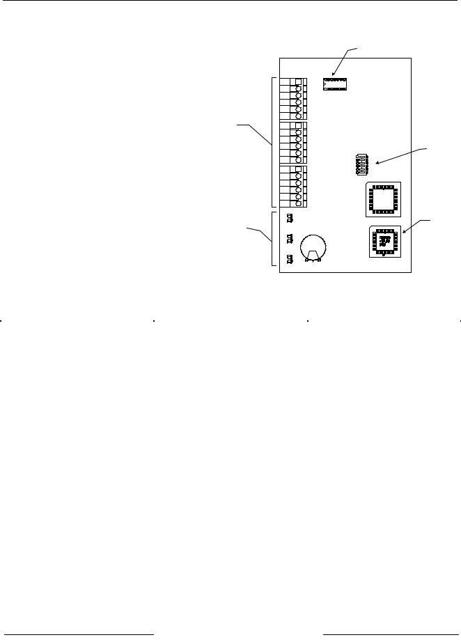
2.2Physical Overview
•Terminal Blocks. The D9210B comes with three banks of terminal blocks for connecting the D9210B to its power source, the panel and associated readers and relays.
•Relay. A removable (model D136) relay provides a dry contact single pull, double throw output.
•Dipswitch. The D9210B dipswitch has six on-off switch settings. Setting these switches allows each unique D9210B to be programmed for a specific address.
•PROM. The D9210B is controlled by a programmable read-only memory microprocessor.
•Diagnostic and Status LEDs. The D9210B has a series of light emitting diodes (LEDs) for identifying operational and diagnostic states. These are listed below.
|
|
Relay |
|
|
D9210B |
|
1 |
|
|
PWR + |
|
|
2 |
|
|
LCKN/C |
|
|
3 |
|
|
LCKCOM |
|
|
4 |
|
|
LCKN/O |
|
|
5 |
|
|
COM |
|
|
6 |
|
|
SDIA |
|
Terminal |
7 |
|
Blocks |
SDIB |
|
8 |
|
|
|
|
|
|
T + |
|
|
9 |
|
|
ZNCOM |
|
|
10 |
DIP Switch |
|
ZN + |
|
|
11 |
ON |
|
RTE |
1 |
|
12 |
|
|
2 |
|
|
COM |
3 |
|
13 |
4 |
|
5 |
|
|
REX |
|
|
6 |
|
|
14 |
|
|
|
|
|
+5.20V |
|
|
15 |
|
|
DATA 0 |
|
|
16 |
|
|
DATA 1 |
|
|
17 |
|
|
BUZZER |
|
|
18 |
|
|
LED |
|
|
|
PROM |
Diagnostic and |
OPER |
|
|
MON |
|
Status LEDs |
|
|
|
|
D0 |
|
READER |
|
|
|
D1 |
|
READER |
|
Figure 1: D9210B Access Control Interface Module
LED |
|
Action |
|
State |
Operational Monitor (Green) |
|
LED blinks on and off |
|
System is operational |
|
|
LED is on or off (solid) |
|
System is off or not operational |
D0 Reader (Green) |
|
LED rapidly blinking |
|
Card data executing |
|
|
LED is off |
|
No card data is being received |
D1 Reader (Yellow) |
|
LED rapidly blinking |
|
Card data executing |
|
|
LED is off |
|
No card data is being sent |
|
Table 3: D9210B Diagnostic and Status LEDs |
|
||
2.3Basic Features, Displays and Reports
2.3.1Basic Features
•Highly reliable and simple to use
•Provides direct interface to 26-bit Weigand card readers.
•Interfaces with (up to eight) D9412 or (up to two) D7412 Control/Communicator panels
•Onboard buzzer output
•Card data LED indicators for low card data when valid format is read
•Operational LED which indicates the CPU is functioning and unit is powered
•Removable onboard relay for switching 12/24 VDC/VAC power
•Option to unlock or lock door upon SDI bus failure
•Supervised Onboard point
•Request to Exit and Request to Enter inputs that can have a shunt only option
•Easily programmable entry/exit door strike and shunt control
D9210B Operation and Installation Guide
© 2002 Bosch Security Systems |
Page 9 |
32206G |
 Loading...