


Wireless Interface Module D8125INV
Operation and Installation Guide

D8125INV
D8125INV Operation and Installation Guide
49690E Page 2 © 2005 Bosch Security Systems

|
|
D8125INV |
|
|
Contents |
1.0 |
Introduction.......................................................................................................................................................................................... |
7 |
1.1 |
FCC Compliance Notice, Part 15 ................................................................................................................................... |
7 |
1.2 |
Other Literature Referenced ............................................................................................................................................ |
7 |
1.3 |
Documentation Conventions ............................................................................................................................................ |
7 |
1.3.1 |
Type Styles Used in this Manual ..................................................................................................................................... |
7 |
1.3.2 |
Tips, Important Notes, Cautions and Warnings........................................................................................................... |
8 |
2.0 |
D8125INV Overview.......................................................................................................................................................................... |
9 |
2.1 |
Features ................................................................................................................................................................. |
9 |
2.2 |
Specifications ................................................................................................................................................................. |
9 |
2.2.1 |
Power..................................................................................................................................................................................... |
9 |
2.2.2 |
System Supervision......................................................................................................................................................... |
10 |
2.2.2.1 |
Watchdog.......................................................................................................................................................................... |
10 |
2.2.2.2 |
Self-Testing ....................................................................................................................................................................... |
10 |
2.3 |
D8125INV Inovonics Interface Module Point Expansion Description.................................................................. |
10 |
2.4 |
D8125INV Back View..................................................................................................................................................... |
10 |
3.0 |
Installation ........................................................................................................................................................................................... |
11 |
3.1 |
Mounting the D8125INV ................................................................................................................................................ |
11 |
3.2 |
Wiring the D8125INV to the Control Panel and FA400 Receiver ....................................................................... |
12 |
3.2.1 |
Setting the Jumper for a second receiver................................................................................................................... |
13 |
3.3 |
D8125INV Quick Startup Recommendations........................................................................................................... |
13 |
3.4 |
Labeling the Inovonics Transmitters ............................................................................................................................ |
13 |
3.5 |
D8125INV Keypad Operation....................................................................................................................................... |
14 |
3.5.1 |
Initial Power-Up ................................................................................................................................................................ |
14 |
3.5.2 |
RF System OK.................................................................................................................................................................. |
15 |
3.5.3 |
Call for Service ................................................................................................................................................................. |
15 |
3.5.4 |
Factory Default Passcode.............................................................................................................................................. |
15 |
3.5.4.1 |
Entering Invalid Passcodes............................................................................................................................................ |
15 |
3.6 |
D8125INV Menu Selections ......................................................................................................................................... |
16 |
3.6.1 |
Beginning steps to add/edit/delete an RF Transmitter ........................................................................................... |
16 |
3.6.1.1 |
Point Mode ........................................................................................................................................................................ |
17 |
3.6.1.2 |
Menu 1: Add, Edit or Delete RF Transmitter ............................................................................................................. |
18 |
3.6.1.3 |
Adding a new RF Transmitter........................................................................................................................................ |
18 |
3.6.1.3 |
Adding an existing RF Transmitter ............................................................................................................................... |
20 |
3.6.1.4 |
Deleting an RF Transmitter ............................................................................................................................................ |
21 |
3.6.1.5 |
Programming the FA570/FA575 Repeater ............................................................................................................... |
21 |
3.6.1.6 |
Programming the FA113 Keyfob.................................................................................................................................. |
22 |
3.6.1.7 |
Programming the D9412GV2, D7412GV2, D7212GV2, D9412G, D7412G, D7212G, D9412, D7412, |
|
D7212, and D9112 Control Panels for RF Transmitters ....................................................................................................... |
22 |
|
3.6.2 |
Menu 2: Change Installer Passcode ........................................................................................................................... |
23 |
3.6.3 |
Menu 3: Set System ID .................................................................................................................................................. |
24 |
3.6.4 |
Menu 4: Clear EEPROM ................................................................................................................................................ |
25 |
3.6.5 |
Menu 5: Set RF System Supervision Interval ............................................................................................................ |
25 |
3.6.6 |
RF Diagnostics Function ................................................................................................................................................ |
26 |
4.0 |
Troubleshooting ............................................................................................................................................................................... |
29 |
4.1 |
FA400 Receiver Supervision ........................................................................................................................................ |
31 |
4.2 |
Missing Transmitters ....................................................................................................................................................... |
31 |
|
D8125INV Operation and Installation Guide |
|
© 2005 Bosch Security Systems |
Page 3 |
49690E |

D8125INV |
|
|
|
Contents |
|
|
|
4.3 |
Low Transmitter Battery Conditions ............................................................................................................................. |
|
31 |
4.4 |
D8125INV Power Cycle Operation.............................................................................................................................. |
|
32 |
4.5 |
Inovonics Frequently Asked Questions ....................................................................................................................... |
|
32 |
4.5.1 What's the range of Inovonics Wireless transmitters? ............................................................................................ |
|
32 |
|
4.5.2 What is the range of the Inovonics Wireless repeater? .......................................................................................... |
|
32 |
|
4.5.3 What does the red decode LED/ light mean? ........................................................................................................... |
|
32 |
|
4.5.4 Does it matter what way I plug in the programming cable?.................................................................................... |
|
32 |
|
4.5.5 How can I get more range?............................................................................................................................................ |
|
32 |
|
4.5.6 Why can't I program more than 1 transmitter per point? ........................................................................................ |
|
32 |
|
4.5.7 Are your transmitters weatherproof?............................................................................................................................ |
|
32 |
|
4.5.8 What is temperature range for good operation?....................................................................................................... |
|
33 |
|
4.5.9 |
Can I externalize an antenna? ........................................................................................................................................ |
|
33 |
4.5.10 |
Does each transmitter need a repeater?..................................................................................................................... |
|
33 |
5.0 |
D8125INV Program Sheet .......................................................................................................................................................... |
|
35 |
|
Figures |
|
|
Table 1: Update Kit Part Numbers .............................................................................................................................................. |
|
7 |
|
Table 2: Other Literature Referenced .......................................................................................................................................... |
|
7 |
|
Table 3: D8125INV Specifications............................................................................................................................................... |
|
9 |
|
Table 4: FA400 Specifications ...................................................................................................................................................... |
|
9 |
|
Figure 1: D8125INV Back View ................................................................................................................................................. |
|
10 |
|
Figure 2: Choosing a Knockout for Wiring Routing (D8103 enclosure shown) .................................................................... |
|
11 |
|
Figure 3: Mounting the D8125INV base ................................................................................................................................... |
|
11 |
|
Figure 4: D8125INV to D9412GV2/D9412G/D9412/D9112 Control Panel Wiring Diagram............................................... |
12 |
||
Figure 5: D8125INV to D7412GV2/D7212GV2/7412G/D7212G/D7412/D7212 Control Panel Wiring .............................. |
13 |
||
Figure 6: Tab to expose keypad.................................................................................................................................................. |
|
14 |
|
Figure 7: D8125INV Keypad...................................................................................................................................................... |
|
14 |
|
Table 5: Key Descriptions........................................................................................................................................................... |
|
14 |
|
Figure 8: Initializing screen ........................................................................................................................................................ |
|
14 |
|
Figure 9: System Defaulted Display ........................................................................................................................................... |
|
14 |
|
Figure 10: RF System Normal .................................................................................................................................................... |
|
15 |
|
Figure 11: Call for Service .......................................................................................................................................................... |
|
15 |
|
Figure 12: Invalid code display .................................................................................................................................................. |
|
15 |
|
Figure 13: Invalid code, Keypad locked display ........................................................................................................................ |
|
15 |
|
Figure 14: D8125INV Menu Selections..................................................................................................................................... |
|
16 |
|
Table 6: Recommended Mode Values ....................................................................................................................................... |
|
17 |
|
Figure 15: RF Transmitter status ............................................................................................................................................... |
|
18 |
|
Figure 16: Connecting cable to D8125INV ............................................................................................................................... |
|
20 |
|
Figure 17: Connecting cable to transmitter............................................................................................................................... |
|
20 |
|
Figure 18: Point Number Status ................................................................................................................................................ |
|
27 |
|
Figure 19: RF Point not programmed ....................................................................................................................................... |
|
27 |
|
Figure 20: Call for Service, Enter Code + ENT ........................................................................................................................ |
|
31 |
|
Figure 21: Call for Service, Receiver Missing ............................................................................................................................ |
|
31 |
|
Figure 22: Call for Service, Enter Code + ENT ........................................................................................................................ |
|
31 |
|
Figure 23: Call for Service, Receiver Missing ............................................................................................................................ |
|
31 |
|
|
D8125INV Operation and Installation Guide |
|
|
49690E |
Page 4 |
© 2005 Bosch Security Systems |
|

|
D8125INV |
|
Contents |
|
Tables |
Table 1: Update Kit Part Numbers ................................................................................................................................................. |
7 |
Table 2: Other Literature Referenced ............................................................................................................................................ |
7 |
Table 3: D8125INV Specifications................................................................................................................................................. |
9 |
Table 4: FA400 Specifications........................................................................................................................................................ |
9 |
Table 5: Key Descriptions.............................................................................................................................................................. |
14 |
Table 6: Recommended Mode Values ....................................................................................................................................... |
17 |
D8125INV Operation and Installation Guide
© 2005 Bosch Security Systems |
Page 5 |
49690E |

D8125INV
Notes:
D8125INV Operation and Installation Guide
49690E Page 6 © 2005 Bosch Security Systems

D8125INV
Introduction
1.0Introduction
This guide covers the installation of the D8125INV Wireless Interface Module for Inovonics Transmitters. The D8125INV is an interface module that allows the connection of an Inovonics FA400 Receiver and compatible transmitters. The D8125INV may be used with the following control panels: D9412G, D7412G, D9412GV2, D7412GV2, D9412, D9112, D7412, and D7212.
Control Panel Firmware Revision Requirements: The control panels listed in Table 1 must have firmware version 6.30 or higher. If you need to upgrade the control panel firmware of a currently installed system, order the following Update Kits from Bosch Security Systems Order Processing:
Control Panel |
Update Kit Part Number |
D9412G, D9412 |
D9499-0650 or higher |
D9112 |
D9199-0650 or higher |
D7412G, D7412 |
D7499-0650 or higher |
D7212 |
D7299-0650 or higher |
|
|
D9412GV2 |
All Revs |
|
|
D7412GV2 |
All Revs |
|
|
D7212GV2 |
All Revs |
Table 1: Update Kit Part Numbers
1.1FCC Compliance Notice, Part 15
This equipment has been tested and found to comply with the limits for a Class B digital device, pursuant to Part 15 of the FCC Rules. These limits are designed to provide reasonable protection against harmful interference in a commercial installation. This equipment generates, uses, and can radiate radio frequency energy, and, if not installed in accordance with the instructions, may cause harmful interference to radio communications. However, there is no guarantee that interference will not occur in a particular installation. If this equipment does cause harmful interference to radio or television reception, which can be determined by turning the equipment on and off, the user is encouraged to try to correct the interference by one or more of the following measures:
1.Reorient or relocate the receiving antenna.
2.Increase the separation between the equipment and the receiver.
3.Connect the equipment into an outlet on a circuit different from that to which the receiver is connected.
4.Consult the dealer or an experienced radio/TV technician for help.
1.2Other Literature Referenced
Throughout this manual, references will be made to other documentation. See the following table for the documents referenced in this manual, which lists the complete part number for ordering purposes.
Name of document |
Part Number |
D9412G/D7412G/D9412GV2/D7412GV2 Program Entry Guide |
47775 |
|
|
D9412G/D7412G/D9412GV2/D7412GV2 Operation and Installation |
43488 |
Manual |
|
|
|
Table 2: Other Literature Referenced
1.3Documentation Conventions
These conventions are intended to call out important features, items, notes, cautions, and warnings that the reader should be aware of in reading this document.
1.3.1Type Styles Used in this Manual
To help identify important items in the text, the following type styles are used:
Bold text |
Usually indicates selections that you may use while programming your control panel. It may also |
|
indicate an important fact that should be noted. |
Bold Italicized |
used to denote notes, cautions and/or warnings |
Italicized text |
Is used to reference the user to another part of this manual or another manual entirely. It is also |
|
used to symbolize names for records that the user will create. |
Courier Text |
Text that appears like this indicates what may appear on the D5200 Programmer display, keypad, |
|
or internal printer. |
[CAPITALIZED TEXT] |
Text like this is used to indicate to the user that a specific key should be pressed. |
|
Example: …press the [ESC] key… |
D8125INV Operation and Installation Guide
© 2005 Bosch Security Systems |
Page 7 |
49690E |

D8125INV
Introduction
1.3.2Tips, Important Notes, Cautions and Warnings
Throughout this document, helpful tips, important notes, cautions and warnings will be presented for the reader to keep in mind. These appear different from the rest of the text as follows:
Important Notes - should be heeded for successful operation and programming. Also tips and shortcuts may be included here.
Caution - These caution the operator that physical damage to the program and/or equipment may occur.
Warning - These warn of the possibility of physical damage to the operator, program and/or equipment.
D8125INV Operation and Installation Guide
49690E Page 8 © 2005 Bosch Security Systems

D8125INV
Overview
2.0D8125INV Overview
2.1Features
•Compatible with Bosch Security Systems D9412GV2, D7412GV2, D7212GV2, D9412G, D7412G, D7212G, D9412, D7412, D7212, and D9112 Control Panels. (FA113 can not be used on the D7212GV2 andD7212G panels)
•Menu driven User Interface
•On the D9412GV2, D9412G, D9412, and D9112, the D8125INV supports up to 2 Inovonics FA400 Receivers (with a maximum of 238 transmitters [119 per bus])
•On the D7412GV2, D7412G, and D7412, the D8125INV supports up to 2 Invonics FA400 Receivers (with a maximum of 67 transmitters)
•On the D7212GV2 and D7212G, the D8125INV supports up to 2 Invonics FA400 Receivers (with up to 32 transmitters in the same location).
•An unlimited number of FA113 Wireless Keyfobs can be added
•Used for diagnostic functions to troubleshoot system RF Transmitters
•Programmable system-wide supervision time interval and individual transmitter check-in time
•Programmable transmitter configuration (Normally Open/Normally Closed, Internal/External Contact, EOL Resistor)
2.2Specifications
User Interface: |
LCD Display |
2 lines by 16 characters, Backlit |
|
Keypad |
0 – 9 numbers |
|
|
ESC, ENT, PREV, NEXT and DIAG keys |
Operating Voltage: |
10.2 - 14 VDC supplied by Aux Power from Control Panel or an External |
|
|
Auxiliary Power Supply. |
|
Current: |
30 mA typical, 45 mA maximum |
|
|
plus ≈ 40 mA for each FA400 receiver |
|
Operating Temperature: |
+32°F to +149°F (0°C to +65°C), 93% Relative Humidity |
|
Wiring: |
18 AWG or 22 AWG Solid or Stranded. Maximum distance from control |
|
|
panel cannot exceed 5 ft. (1.5 m). |
|
Dimensions (HxWxD): |
3.94 in. x 6.5 in. x 1.2 in. (10 cm x 16.6 cm x 3 cm) |
|
Weight: |
8.6 oz. (243 g) |
|
|
Table 3: D8125INV Specifications |
|
|
|
|
Operating Voltage: |
10.2 VDC to 14 VDC |
|
Curent: |
40 mA Max. |
|
Wiring: |
18 AWG or 22 AWG Solid or Stranded. Maximum distance from D8125INV |
|
|
to FA400 cannot exceed 200 ft. (61 m) or 1000 ft. (305 m) with power supply. |
|
|
Table 4: FA400 Specifications |
|
2.2.1Power
If the D8125INV is powered down and then back up, it may take up to a maximum of 5 minutes (up to 15 minutes for 5 minute Transmitter Check-In Time) for all the transmitters to report back to the D8125INV with their current status. On systems employing fewer transmitters, this time is reduced proportionately.
In addition, when the D8125INV is powered up, all programmed RF points will report Normal until their state is updated.
The D8125INV power should be connected to the control panel using the Aux Power terminals. If the D8125INV were to lose power, the following conditions may result:
•All RF points will report to the control panel as missing (trouble/alarm)
D8125INV Operation and Installation Guide
© 2005 Bosch Security Systems |
Page 9 |
49690E |
D8125INV
Overview
•All RF points will initialize in a normal state when power is reapplied
•Alarms initiated prior to power loss would be reset. If the alarm conditions persist when power is restored, new alarms would be generated.
Note: Programmed settings such as RF point configuration and System ID will remain intact upon the event of a power loss.
2.2.2System Supervision
2.2.2.1 Watchdog
The D8125INV implements a watchdog software. Failure of the program will result in a software reset within two seconds. This may cause a trouble condition on the control panel for the duration of the reset.
2.2.2.2 Self-Testing
The D8125INV EEPROM memory is automatically tested on a periodic basis. The EEPROM checksum is verified every ten minutes. If the EEPROM checksum fails, a point bus trouble condition will be seen at the control panel.
2.3D8125INV Inovonics Interface Module Point Expansion Description
Using two D8125INVs, you can program up to 238 (119 per bus) Inovonics Wireless Transmitters to the system on the D9412GV2, D7412GV2, D9412G, D7412G, D9412, D7412, D7212, and D9112 allow up to 67 Inovonics Wireless Transmitters, and D7212GV2 and D7212G allow up to 32 Invonics wireless transmitters.
The D8125INV is an integrated interface module and keypad. The keypad is used to access the programming, and diagnostic functions of the wireless portion of the system. The integrated keypad on the D8125INV is physically different looking from the typical keypads (D1255, D1256, D1257, and so on) so that it will not be mistaken for a system keypad. When mounting the D8125INV, it must be within 5 feet (of the control panel. It has been designed such that it should be mounted right next to the D8103, D8108A or D8109 enclosure.
The D9412GV2, D7412GV2, D7212GV2, D9412G, D7412G, D7212G, D9412, D7412, D7212, and D9112 Control Panels can have both hardwired (D8128D OctoPOPITS, D8125 Popex / D9127 POPITS, D8125MUX) and wireless points connected at the same time.
To add wireless points, an Inovonics FA400 Receiver must be connected to the D8125INV which is then connected to the control panel’s Zonex 1 (and/or Zonex 2) terminals and Aux Power. For best transmitter reception results, the FA400 should be centrally located among the transmitters. If transmitters are at too great of a distance for the FA400 Receiver to pick up the transmission, an Inovonics RF Repeater may be installed.
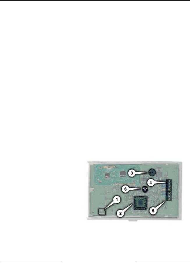
2.4D8125INV Back View
See Figure 1 for areas of importance on the
D8125INV,
1.Programming Jack (Access using front panel)
2.EPROM Socket – contains EPROM with encoded software
3.Sounder to indicate valid and invalid entry via the keypad
4.4-Wire Zonex Power Panel Connection Terminal Strip
5.FA-400 Receiver Terminal Strip
6.LCD Contrast Adjustment
The D8125INV provides connection to a control panel using a Zonex 4-wire interface and to a FA-400 Receiver via a 3-wire interface.
Figure 1: D8125INV Back View
D8125INV Operation and Installation Guide
49690E Page 10 © 2005 Bosch Security Systems
D8125INV
Installation
3.0Installation
The D8125INV is packaged with a Point Label Sheet. Save these, as you will use them when identifying the point numbers on the Inovonics transmitters.
3.1Mounting the D8125INV
1.Select the knockout from the control panel enclosure that will be used to route the wiring.
2.Select the location from which the Inovonics FA400 Receiver wiring will be routed.
Wire |
Knockouts |
|
|
Figure 2: Choosing a Knockout for Wiring |
|
|
Routing (D8103 enclosure shown) |
3. |
Remove the base of the |
|
|
D8125INV and use the |
|
|
screws provided with the unit |
|
|
to mount it adjacent to the |
|
|
control panel. |
|
4. |
Connect the wiring (see |
|
|
Section 3.2 Wiring the |
D8125INV |
|
D8125INV to the Control |
Base |
|
Panel and FA400 Receiver) to |
|
|
the D8125INV and mount |
|
|
the cover unit to the base. |
|
|
|
Control Panel |
|
|
Enclosure |
|
|
Figure 3: Mounting the D8125INV base |
D8125INV Operation and Installation Guide
© 2005 Bosch Security Systems |
Page 11 |
49690E |

D8125INV
Installation
3.2Wiring the D8125INV to the Control Panel and FA400 Receiver
The Inovonics FA400 Receiver may be located up to 200 ft. (61 m) from the D8125INV. If the installation requires the receiver to be mounted farther than this, an external power supply is required. The maximum distance in any case is 1000 ft. (305 m). For optimal mounting instructions, please refer to the instructions supplied by Inovonics.
If an external power supply is used to power the FA400 Receiver, you must:
a)connect the negative terminal wire of the external power supply to the GND terminal of the D8125INV and the GND terminal of the FA400.
b)if Ground Fault Detect is enabled on the D9412GV2, D9412G, D7412GV2, or D7412G, use a Ground Isolated Power Supply.
Certain installation configurations may require a second FA400 Receiver (see Section 3.2.1 Setting the Jumper for a second receiver, p.13.)
Disconnect all power to the Control Panel and to the D8125INV before beginning any work with the internal components.
Refer to Figure 4 and Figure 5 for the proper wiring connections.
FA400 Receiver
D9412GV2/D9412G/D9412/D9112
Control Communicator Panel
Vs GND OUT
FA400 Receiver
Vs GND OUT
D8125INV (Points 9-127)
+12v  IN
IN  OUT
OUT  GND
GND  +12v
+12v  DATA
DATA  GND
GND
FA400 Receiver
Vs GND OUT
FA400 Receiver
Vs GND OUT |
D8125INV |
(Points 129-247) |
+12v |
IN |
OUT |
GND |
+12v |
DATA |
GND |
Figure 4: D8125INV to D9412GV2/D9412G/D9412/D9112 Control Panel Wiring Diagram
D8125INV Operation and Installation Guide
49690E |
Page 12 |
© 2005 Bosch Security Systems |
 Loading...