


D9412GV3/D7412GV3
Operation and Installation Guide
EN Control Panels

D9412GV3/D7412GV3 | Operation and Installation Guide | Trademarks
Trademarks
CoBox is a registered trademark of Lantronix.
Windows is a registered trademark of Microsoft Corporation in the United States or in other countries.
Molex is a registered trademark of Molex Incorporated.
Certifications and Approvals
The D9412GV3/D7412GV3 Literature Pack includes the D9412GV3/D7412GV3 Approved Applications Compliance Guide (P/N: F01U143069). Refer to this guide for additional guidelines on installing the control panels in Underwriters Laboratories Inc. (UL) and firespecific applications.
Listings and Approvals
UL
The D9412GV3 and D7412GV3 Control Panels are UL Listed for Central Station, Local, Auxiliary, Proprietary, and Household Fire Alarm, and Central Station, Local, Police Station Connect, Household Burglar Alarm and Encrypted line Security when communicating via a network.
Department of Defense (DOD)
The D9412GV3/D7412GV3 was granted approval for Department of Defense (DoD) installations in Sensitive Compartmented Information Facilities (SCIF).
Federal Communications Commission (FCC) Rules
Part 15
This equipment was tested and found to comply with the limits for a Class A digital device, pursuant to Part 15 of the FCC rules. These limits are designed to provide reasonable protection against harmful interference when the equipment is operated in a commercial environment.
This equipment generates, uses, and can radiate radio frequency energy; and if not installed and used according to the instructions, can cause harmful interference to radio communications.
Operation of this equipment in a residential area is likely to cause harmful interference, in which case the user is required to correct the interference at his or her own expense.
Part 68
This equipment complies with Part 68 of FCC rules. A label contains, among other information, the FCC registration number and ringer equivalence number (REN). If requested, this information must be provided to the telephone company.
The D9412GV3 and D7412GV3 Control Panels are registered for connection to the public telephone network using an RJ38X or RJ31X jack.
The REN is used to determine the number of devices that can be connected to the telephone line. Excessive RENs on the telephone line may result in the devices not ringing in response to an incoming call. In most, but not all areas, the sum of the RENs should not exceed five. To be certain of the number of devices that may be connected to the line, as determined by the RENs, contact the telephone company to determine the maximum REN for the calling area.
If you experience trouble with the control panel, please contact Bosch Security Systems Customer Service for repair and warranty information. If the trouble is causing harm to the telephone network, the telephone company might request that the equipment be removed from the network until the problem is resolved. User repairs must not be made, and doing so will void the user’s warranty.
If the D9412GV3 or D7412GV3 Control Panel causes harm to the telephone network, the telephone company attempts to notify you in advance. If advance notice is not practical, the telephone company notifies you as soon as possible. Also, you will be advised of your right to file a complaint with the FCC if you believe it is necessary.
Bosch Security Systems, Inc. | 10/10 | F01U143070-03 |
2 |

D9412GV3/D7412GV3 | Operation and Installation Guide | Federal Communications Commission (FCC) Rules
The telephone company might make changes in its facilities, equipment, operations, or procedures that could affect the operation of the equipment. If this happens, the telephone company provides advance notice in order for the necessary modifications to be made in order to maintain uninterrupted service.
This equipment cannot be used on public coin service provided by the telephone company. Connection to Party Line service is subject to state tariffs. (Contact your state public utilities commission for information.)
FCC Registration Number:
US:ESVOT00BD9412GV3
Service Center in USA:
Bosch ST Service Center
8601 East Cornhusker Hwy Dock B
Lincoln, NE 68507 - 9702 USA
Ringer Equivalence: 0.0B
Bosch Security Systems, Inc. | 10/10 | F01U143070-03 |
3 |

D9412GV3/D7412GV3 | Operation and Installation Guide | Contents
Contents |
|
|
1.0 |
Introduction ...................................................... |
7 |
2.0 |
Lightning Strikes ............................................. |
8 |
2.1 |
Effects ................................................................. |
8 |
2.2 |
Precautions during Installation ........................ |
8 |
3.0 |
Overview............................................................ |
9 |
3.1 |
Configuration and Parts.................................... |
9 |
3.1.1 |
Parts List ........................................................... |
10 |
3.1.2 |
Parts Available by Separate Order ............... |
10 |
3.2 |
Accessories ...................................................... |
11 |
3.3Features in the D9412GV3 and D7412GV3 12
3.3.1 |
SDI Molex Connector...................................... |
12 |
3.3.2 |
Tip and Ring Posts .......................................... |
12 |
3.3.3 |
Telephone Line Sniff ....................................... |
12 |
3.3.4 |
Points ................................................................ |
12 |
3.3.5 |
Areas and Accounts ........................................ |
12 |
3.3.6 |
Digital Communicator...................................... |
12 |
3.3.7 |
Keypads ............................................................ |
13 |
3.3.8 |
Keyswitch.......................................................... |
13 |
3.3.9 |
Access Control................................................. |
13 |
3.3.10 |
Event Memory .................................................. |
13 |
3.3.11 |
Event Log.......................................................... |
13 |
3.3.12 |
Ground Fault Detection .................................. |
13 |
3.3.13 |
Ground Fault Detection Added Feature ....... |
14 |
3.3.14 |
Conettix Functions........................................... |
14 |
3.3.15 |
Programming.................................................... |
14 |
3.3.16 |
Other Features................................................. |
14 |
4.0 |
Installation....................................................... |
14 |
4.1 |
Installation Preparation ................................... |
14 |
4.2 |
Enclosure Options ........................................... |
14 |
4.3 |
Mounting Enclosure ........................................ |
14 |
4.4 |
Installing the Control Panel ............................ |
15 |
4.5 |
Connecting Earth Ground............................... |
15 |
4.5.1 |
Terminal 10....................................................... |
15 |
4.5.2 |
Ground Fault Detect Enable .......................... |
15 |
4.5.3 |
Enabling Ground Fault Detection .................. |
16 |
4.5.4 |
Ground Fault Specifications........................... |
16 |
4.5.5 |
Locking the Reset Pin ..................................... |
16 |
4.6 |
Completing the Installation............................. |
17 |
4.6.1 |
Charging the Battery ....................................... |
17 |
4.6.2 |
Installing and Wiring Detection Devices....... |
17 |
4.6.3 |
Installing Modules and Relays....................... |
17 |
4.6.4Connecting the On-board Points and
Keypads ............................................................ |
17 |
4.6.5 Powering Up..................................................... |
17 |
4.7 |
Programming the Control Panel.................... |
17 |
4.8 |
Installing the Point Chart Label ..................... |
18 |
4.9 |
Testing the System ......................................... |
18 |
4.10 |
Service Walk Test ........................................... |
18 |
5.0 |
Power Supply ................................................. |
22 |
5.1 |
Primary Power Terminals 1 and 2 ................ |
22 |
5.1.1 |
Primary (AC) Power Circuit............................ |
22 |
5.1.2 |
Installing the Transformer .............................. |
22 |
5.2 |
Secondary Power Terminals ......................... |
22 |
5.2.1 |
Secondary (DC) Power .................................. |
22 |
5.2.2 |
Installing the Battery........................................ |
22 |
5.2.3 |
Replacing the Battery ..................................... |
24 |
5.2.4 |
Battery Supervision......................................... |
24 |
5.2.5 |
Battery Charging Circuit ................................. |
24 |
5.2.6Battery Discharge and Recharge Schedule 25
6.0 |
Power Outputs ............................................... |
26 |
6.1 |
Circuit Protection ............................................. |
26 |
6.2 |
Total Available Power..................................... |
26 |
6.3Continuous Power Output Terminals 3, 8, 24,
and 32 ............................................................... |
26 |
6.4Programmable Power Output Terminals 6, 7,
|
and 8 ................................................................. |
27 |
6.4.1 |
Programming ................................................... |
27 |
6.4.2 |
Terminals 6 and 7 ........................................... |
27 |
6.4.3 |
Fire System Power Formula .......................... |
27 |
6.4.4 |
Terminal 8......................................................... |
27 |
7.0 |
Telephone Connections .............................. |
28 |
7.1 |
Registration ...................................................... |
28 |
7.2 |
Notification........................................................ |
28 |
7.3 |
Location ............................................................ |
28 |
7.4 |
Telephone Cord Connection.......................... |
28 |
7.5 |
Phone LED (Red) ............................................ |
29 |
7.6 |
Operation Monitor LED (Green).................... |
29 |
7.7 |
Dialing Format ................................................. |
29 |
7.8 |
Telephone Line Monitor.................................. |
29 |
7.9 |
Called Party Disconnect................................. |
29 |
7.10 |
Communication Failure .................................. |
29 |
7.11 |
D928 Dual Phone Line Switcher ................... |
30 |
7.11.1 |
Description ....................................................... |
30 |
7.11.2 |
Operation.......................................................... |
30 |
7.11.3 |
Installing the D928 .......................................... |
31 |
7.11.4 |
D928 Status LEDs........................................... |
31 |
8.0 |
On-Board Points............................................ |
31 |
8.1 |
Terminals 11 to 22 Description ..................... |
31 |
8.2 |
Point Sensor Loops......................................... |
31 |
8.3 |
Point Parameters............................................. |
32 |
8.4 |
Point Response Time ..................................... |
33 |
Bosch Security Systems, Inc. | 10/10 | F01U143070-03 |
4 |

D9412GV3/D7412GV3 | Operation and Installation Guide | Contents
8.5Wiring Information for Installations Using the
|
Rothenbuhler 5110/4001-42 High Security |
|
|
Bell ..................................................................... |
33 |
9.0 |
Off-Board Points............................................ |
36 |
9.1Point (Zonex) Bus: D9412GV3 Terminals and
|
D7412GV3 Terminals ..................................... |
36 |
9.1.1 |
POPIT Modules................................................ |
36 |
9.1.2 |
POPEX Modules.............................................. |
36 |
9.1.3 |
Missing Conditions .......................................... |
36 |
9.1.4 |
Extra Point Events........................................... |
36 |
9.1.5D9412GV3/D7412GV3 Responses to Missing
|
Point Conditions............................................... |
37 |
9.2 |
D8125 and D9127 POPIT Modules .............. |
37 |
9.3 |
Installing the D8125 POPEX Module............ |
40 |
9.3.1 |
Mounting ........................................................... |
40 |
9.3.2 |
Wiring the D8125 to the Control Panel......... |
40 |
9.3.3Wiring POPITs to the Data Expansion Loop40
9.3.4Wiring Data Expansion Loops to POPEX
|
Modules............................................................. |
41 |
9.3.5 |
POPIT Sensor Loops ...................................... |
41 |
9.3.6 |
POPIT Module Point Assignments................ |
41 |
9.3.7 |
Program Record Sheet ................................... |
41 |
9.3.8 |
POPIT Labels................................................... |
42 |
9.4 |
D8128D OctoPOPIT Module ......................... |
42 |
9.4.1 |
Description........................................................ |
42 |
9.4.2 |
Listings .............................................................. |
43 |
9.4.3 |
Installation......................................................... |
44 |
9.4.4 |
Setting the OctoPOPIT Switches .................. |
44 |
9.4.5 |
Mounting OctoPOPITs.................................... |
45 |
9.4.6 |
Wiring OctoPOPITs......................................... |
45 |
9.4.7 |
OctoPOPIT Sensor Loops.............................. |
49 |
9.5 |
Testing Off-Board Points ................................ |
49 |
10.0 Off-Board Relays................................................. |
50 |
|
10.1 |
D8129 OctoRelay ............................................ |
50 |
10.1.1 |
Configuring the D8129 OctoRelay ................ |
51 |
10.1.2 |
Relay Outputs .................................................. |
51 |
10.1.3 |
Installation......................................................... |
51 |
10.1.4 |
Wiring Connections ......................................... |
52 |
10.2 |
D811 Arm Status Relay Module .................... |
52 |
10.2.1 |
Relay Output .................................................... |
52 |
10.2.2 |
Installation......................................................... |
52 |
10.2.3 |
Wiring Connections ......................................... |
53 |
11.0 Arming Devices................................................... |
55 |
|
11.1 |
Description........................................................ |
55 |
11.2 |
Keypad Terminals 29 to 32 ............................ |
55 |
11.2.1 |
Assigning an Address for the Keypad .......... |
55 |
11.2.2 |
Installation......................................................... |
56 |
11.3 |
D279A Independent Zone Control ................ |
57 |
11.4 |
Keyswitch ......................................................... |
57 |
11.4.1 |
Description ....................................................... |
57 |
11.4.2 |
Programming ................................................... |
57 |
11.4.3 |
Installation ........................................................ |
57 |
11.4.4 |
Operation.......................................................... |
57 |
12.0 SDI Devices.......................................................... |
59 |
|
12.1 |
Description ....................................................... |
59 |
12.2 |
Installation ........................................................ |
59 |
12.3 |
D9131A Parallel Printer Interface Module ... |
59 |
12.3.1 |
Switch Settings ................................................ |
59 |
12.3.2 |
Supervision....................................................... |
59 |
12.4D9210B Wiegand Control Interface Module 60
12.4.1 |
Access .............................................................. |
60 |
12.4.2 |
Switch Settings ................................................ |
60 |
12.5 |
SDI Addresses 88 and 92 .............................. |
60 |
12.5.1 |
D9133DC Direct Connect Programming |
|
|
Module .............................................................. |
60 |
12.5.2 |
Network Interface Modules ............................ |
61 |
12.5.3 |
Address Settings ............................................. |
61 |
12.5.4 |
Supervision....................................................... |
61 |
13.0 Programmer and Accessory Connections... |
62 |
|
13.1 |
Programmer Connector.................................. |
62 |
13.2Installer Keypad and Local Programmers
|
Mode ................................................................. |
62 |
13.3 |
Programmer Access Reports ........................ |
62 |
13.4 |
Accessory Connector...................................... |
63 |
14.0 Faceplates ............................................................ |
64 |
|
14.1 |
D9412GV3 Faceplate ..................................... |
64 |
14.2 |
D7412GV3 Faceplate ..................................... |
65 |
Appendix A: System Wiring Diagrams, Issue A.. |
66 |
|
A.1 |
D9412GV3 Control Panel .............................. |
66 |
A.2 |
D7412GV3 Control Panel .............................. |
69 |
Appendix B: Point Address Charts ........................ |
72 |
|
B.1 |
Zonex 1, Points 9 to 127 (D9412GV3); Zonex |
|
|
1, Points 9 to 75 (D7412GV3) ....................... |
72 |
B.2 |
Zonex 2, Points 129 to 247 (D9412GV3 Only) |
|
|
........................................................................... |
73 |
Specifications............................................................... |
74 |
|
SDI Bus A (+): ................................................................ |
74 |
|
Connection: .................................................................... |
74 |
|
Two Telco lines:............................................................. |
74 |
|
Discharge Cycle............................................................. |
74 |
|
Bosch Security Systems, Inc. | 10/10 | F01U143070-03 |
5 |

D9412GV3/D7412GV3 | Operation and Installation Guide | Tables
|
Figures |
|
Figure 1: |
System Configuration ................................ |
9 |
Figure 2: |
Enclosure Mounting ................................. |
15 |
Figure 3: |
Enabling Ground Fault Detection........... |
16 |
Figure 4: |
Reset Pin ................................................... |
16 |
Figure 5: |
D9412GV3 Service Walk Test Flow Chart |
|
|
.................................................................... |
20 |
Figure 6: |
D7412GV3 Service Walk Test Flow Chart |
|
|
.................................................................... |
21 |
Figure 7: |
Battery Terminals ..................................... |
23 |
Figure 8: |
Non-Power-Limited Wiring ...................... |
23 |
Figure 9: |
Charging and Battery LEDs .................... |
24 |
Figure 10: |
RJ31X Wiring ............................................ |
28 |
Figure 11: |
Phone Connector, Phone LED, and |
|
|
Operation Monitor LED Locations.......... |
28 |
Figure 12: |
D928 Dual Phone Line Switcher ............ |
30 |
Figure 13: |
On-board Point Sensor Loop Wiring...... |
32 |
Figure 14: |
Rothenbuhler 5110/4001-42 High |
|
|
Security Bell Wiring Configuration ......... |
34 |
Figure 15: |
Wiring the Rothenbuhler 5110/4001-42 |
|
|
High Security Bell to the D9412GV3 or |
|
|
D7412GV3 Control Panel........................ |
35 |
Figure 16: |
Connecting the D8125 POPEX to the |
|
|
D9412GV3 Control Panel........................ |
38 |
Figure 17: |
Connecting the D8125 POPEX to the |
|
|
D7412GV3 Control Panel........................ |
39 |
Figure 18: |
Program Record Sheet............................ |
42 |
Figure 19: |
D8128D OctoPOPIT Layout ................... |
43 |
Figure 20: |
Connecting D8128D OctoPOPITs to the |
|
|
D9412GV3................................................. |
46 |
Figure 21: |
Connecting D8128D OctoPOPITs to the |
|
|
D7412GV3................................................. |
47 |
Figure 22: |
Wiring Multiple D8128Ds Using Molex® |
|
|
Connectors ................................................ |
48 |
Figure 23: |
D8128D OctoPOPIT Sensor Loops....... |
49 |
Figure 24: |
D8129 Connections to the D9412GV3.. |
50 |
Figure 25: |
D8129 Connections to the D7412GV3.. |
51 |
Figure 26: |
D811 Module Wiring to the D9412GV3.53 |
|
Figure 27: |
D811 Module Wiring to the D7412GV3.54 |
|
Figure 28: |
Power at Keypads .................................... |
57 |
Figure 29: |
Keyswitch Wiring ...................................... |
58 |
Figure 30: |
DX4020 DIP Switch Settings .................. |
61 |
Figure 31: |
Reset Pin ................................................... |
62 |
Figure 32: |
Programmer and Accessory Connections |
|
|
.................................................................... |
63 |
Figure 33: |
D9412GV3 Faceplate .............................. |
64 |
Figure 34: |
D7412GV3 Faceplate .............................. |
65 |
Figure 35: |
D9412GV3, Power Supply Side System |
|
|
Wiring ......................................................... |
66 |
Figure 36: |
D9412GV3, Input Points and Peripheral |
|
|
Devices System Wiring ........................... |
67 |
Figure 37: |
D9412GV3, SDI Devices System Wiring |
|
|
System Wiring........................................... |
68 |
Figure 38: |
D7412GV3, Power Supply Side System |
|
|
Wiring......................................................... |
69 |
Figure 39: |
D7412GV3, Input Points and Peripheral |
|
|
Devices System Wiring ........................... |
70 |
Figure 40: |
D7412GV3, SDI Devices System Wiring |
|
|
.................................................................... |
71 |
Tables |
|
|
Table 1: |
Related Documentation............................. |
7 |
Table 2: |
GV3 Series Control Panel Differences ... |
9 |
Table 3: |
Compatible Accessories1 ........................ |
11 |
Table 4: |
Compatible Keypads................................ |
13 |
Table 5: |
Ground Fault Impedance Specifications16 |
|
Table 6: |
Battery Discharge and Recharge |
|
|
Schedule.................................................... |
25 |
Table 7: |
Charging Status and Low Battery LEDs25 |
|
Table 8: |
Phone Cord Lengths................................ |
31 |
Table 9: |
Point Parameters ..................................... |
32 |
Table 10: |
POPEX Modules ...................................... |
36 |
Table 11: |
Extra Point Events ................................... |
36 |
Table 12: |
Off-Board Point Errors............................. |
37 |
Table 13: |
Data Expansion Loop Wire Specifications |
|
|
.................................................................... |
40 |
Table 14: |
D8128D OctoPOPIT Switch Settings for |
|
|
D9412GV3 and D7412GV3 .................... |
44 |
Table 15: |
Switch 5 Settings for Line Termination . 44 |
|
Table 16: |
Terminal Strip Connections .................... |
45 |
Table 17: |
D8129 OctoRelay Switch Settings......... |
51 |
Table 18: |
Number of D8128Ds Used with D8129s52 |
|
Table 19: |
Keypad Address Settings........................ |
55 |
Table 20: |
Keypad Connections ............................... |
56 |
Table 21: |
SDI Device Connections ......................... |
59 |
Table 22: |
Printer Address Switch Settings............. |
59 |
Table 23: |
Address Switch Settings for Access |
|
|
Control Module ......................................... |
60 |
Table 24: |
Zonex 1 Point Address Chart ................. |
72 |
Table 25: |
Zonex 2 Point Address Chart ................. |
73 |
Table 26: |
Specifications............................................ |
74 |
Bosch Security Systems, Inc. | 10/10 | F01U143070-03 |
6 |

D9412GV3/D7412GV3 | Operation and Installation Guide | |
1.0 |
Introduction |
|
|
|
1.0 Introduction
This manual addresses the operation and installation of the D9412GV3 and D7412GV3 Control Panels. Throughout this guide, the words “control panel” refer to both control panels (D9412GV3 and D7412GV3). Table 2 on page 9 provides an overview of the differences in the control panels.
To obtain any of the documents in Table 1, contact Bosch Security Systems, Inc. Customer Service at (800) 289-0096 and request the documentation by its corresponding part number.
Table 1: Related Documentation
|
|
|
|
|
Product Type |
Name of Documentation |
Part Number |
|
Control Panels |
D9412GV3/D7412GV3 Release Notes |
F01U143073 |
|
|
D9412GV3/D7412GV3 Approved Applications Compliance Guide |
F01U143069 |
|
|
D9412GV3/D7412GV3 Operation and Installation Guide (this document) |
F01U143070 |
|
|
D9412GV3/D7412GV3 Program Entry Guide |
F01U170807 |
|
|
D9412GV3/D7412GV3 Program Record Sheet |
F01U170809 |
|
|
UL Certificated Bank Safe and Vault Applications Technogram |
73-07302-000 |
|
Keypads |
D1255RB/D1256RB/D1257RB Installation Instructions |
F01U011791 |
|
|
D1255/D1255B Installation Instructions |
74-06819-000 |
|
|
D1256/D1257 Installation Instructions |
74-06925-000 |
|
|
D1260/D1260B Installation Guide |
48101 |
|
|
D1260/D1260B Owner’s Manual |
50410 |
|
|
D720 Series Installation Instructions |
74-06918-000 |
|
|
D279A Operation and Installation Instructions |
46458 |
|
|
Security System Owner's Manual |
71-06633-000 |
|
|
GV3 Series Owner's Manual Supplement |
F01U143082 |
|
|
|
|
|
Programming |
RPS Installation Guide |
4998141259 |
|
Tools |
|
|
|
Expansion |
D8128D Installation Guide |
F01U070537 |
|
Devices |
|
|
|
D8125MUX Operation & Installation Guide |
F01U034973 |
|
|
|
ISW-D8125CW-V2 Installation & Operation Guide |
F01U161691 |
|
|
D9210B Operation and Installation Guide |
32206 |
|
These products meet the requirements for UL 864 Commercial Fire applications. |
|
Bosch Security Systems, Inc. | 10/10 | F01U143070-03 |
7 |

D9412GV3/D7412GV3 | Operation and Installation Guide | |
2.0 |
Lightning Strikes |
|
|
|
2.0 Lightning Strikes
The control panels are designed to significantly reduce electromagnetic interference and malfunction generally caused by lightning.
2.1Effects
Any electronic system can be struck directly by lightning or be adversely affected by a lightning strike near the system. When lightning strikes, several things happen:
An electromagnetic wave spreads from the point of the strike inducing high voltages in nearby conductors.
The voltage changes substantially on electrical grounds near the lightning strike.
High voltages are induced in anything directly struck by lightning.
The effects of a lightning strike can include Missing Trouble, Missing Alarm, or Point Bus Trouble events. Occasionally, Reboot and Watchdog events might be sent because the control panel tried to reset itself.
Electronic systems, including control panels, cannot be completely immune to direct or indirect lightning strikes; however, some proven installation practices might greatly reduce the risk of undesirable affects.
2.2Precautions during Installation
To minimize the risk of undesirable effects from lightning strikes on high risk installations that use a point-bus technology:
Do not run wiring outside the building.
If you must install the unit in a metal building, keep the wiring at least 0.61 m (2 ft) away from external metal surfaces.
Earth ground the unit correctly. Do not use an electrical ground or telephone ground.
Avoid running wires near telephone, data, or power lines inside a building. Historical evidence shows that locating control panel wiring at least 0.61 m (2 ft) away from telephone, data, or power lines is successful at minimizing lightning damage. When your data lines must cross the path of AC or other wiring, cross the lines perpendicularly.
Bosch Security Systems, Inc. | 10/10 | F01U143070-03 |
8 |
D9412GV3/D7412GV3 | Operation and Installation Guide | |
3.0 |
Overview |
|
|
|
3.0Overview
3.1Configuration and Parts
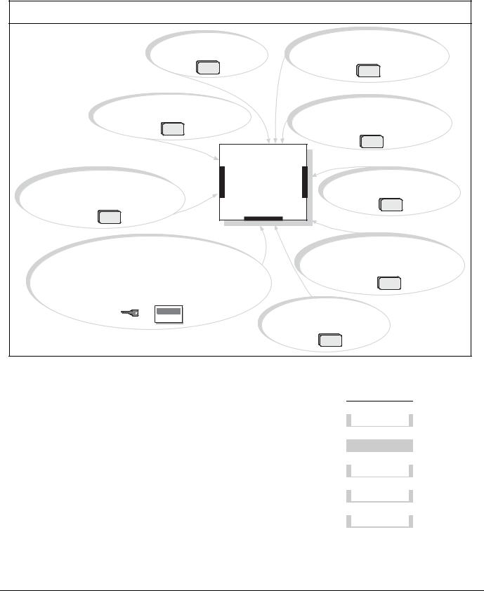
Figure 1: System Configuration
D9210B Modules can be used for access control.
Each D8128D OctoPOPIT combines eight POPIT points in one module.
D8129 OctoRelay provides alarm and auxiliary relay output.
(Other functions available.)
DX4020 or ITS-DX4020-G allows communciation over a Local or Wide Area Network (LAN/WAN).
D8125, ISW-D8125CW-V2 or D8125MUX Interface used for point expansion.
Control |
Panel |
On-Board Points |
1 to 8 |
D928 Module allows the control panel to monitor two phone lines.
Use keypads or keyswitches to arm the control panel by area. The D9412GV3 control panel supports up to 32 areas. The D7412GV3 control panel supports up to 8 areas. Each area can have its own account number or areas can be grouped together with a common account number. Points of protection are assigned to areas.
D8132 Modules (two 12 VDC batteries) provide additional power for keypads and other powered devices.
D9131A Module connects to a parallel printer to print the event log.
|
Table 2: |
GV3 Series Control Panel Differences |
|
|
|
|
||
|
|
|
|
|
|
|
|
|
|
|
|
|
|
|
|
|
|
|
Features |
|
|
D9412GV3 |
D7412GV3 |
|
D7212GV3 |
|
|
|
|
|
|
|
|
||
|
Access Control |
|
Yes - 8 doors |
Yes - 2 doors |
|
No |
|
|
|
Arm/Disarm Passcodes |
|
|
|
|
|||
|
249 |
99 |
|
99 |
|
|||
|
Cards/Tokens |
|
996 |
396 |
|
N/A |
|
|
|
Passcode-Protected Custom Functions |
16 |
4 |
|
4 |
|
||
|
|
|
|
|
|
|||
|
Number of Printers |
|
3 |
1 |
|
1 |
|
|
|
Number of Points |
246 |
75 |
|
40 |
|
||
|
|
|
|
|
|
|||
|
Number of Relays |
|
128 |
64 |
|
24 |
|
|
|
Number of Areas |
32 |
8 |
4 |
|
|||
|
|
|
|
|
|
|||
|
Number of D1255 Keypads |
|
16 |
16 |
|
8 |
|
|
|
Number of D1260 Keypads |
8 |
8 |
8 |
|
|||
|
|
|
|
|
|
|
|
|
Bosch Security Systems, Inc. | 10/10 | F01U143070-03 |
9 |

D9412GV3/D7412GV3 | Operation and Installation Guide | |
3.0 |
Overview |
|
|
|
3.1.1Parts List
The D9412GV3 andD7412GV3 Control Panels are shipped assembled from the factory with the following parts:
Literature Pack
D9412GV3/D7412GV3 Program Record Sheet
(P/N: F01U170809)
7000/9000 Series Point Chart Label
(P/N: 79-06660-000)
Assembly
PC board
Faceplate shield
Mounting skirt
One #6 x 1/4-in. screw
3.1.2Parts Available by Separate Order
Order the following components separately to complete a basic eight-point installation.
The D1260 and D1260B Keypads must have firmware version 1.04 or higher for use with the D9412GV3 and D7412GV3.
D1255B, D1255, D1256, D1260, D1260B Keypad, or D720 Keypad
D1255RB Fire Keypad, D1256RB Fire Keypad, or D1257RB Fire Alarm Annunciator
D1640 Transformer
D126 or D1218 Battery
D161 or D162 Phone Cord (order two cords if using the D928 Dual Phone Switcher)
D8103, D8108A, or D8109 Enclosure
Configured packages are also available. Please consult the Bosch Security Systems, Inc. Product Catalog.
The following literature is available in a separate literature package for dealers.
D9412GV3/D7412GV3 Operation and Installation Guide (P/N: F01U143070)
D9412GV3/D7412GV3 Approved Applications Compliance Guide (P/N: F01U143069)
D9412GV3/D7412GV3 Program Entry Guide
(P/N: F01U170807)
D9412GV3/D7412GV3 Program Record Sheet
(P/N: F01U170809)
Bosch Security Systems, Inc. | 10/10 | F01U143070-03 |
10 |
D9412GV3/D7412GV3 | Operation and Installation Guide | |
3.0 |
Overview |
|
|
|
3.2Accessories
Refer to the Bosch Security Systems, Inc. product catalog for additional information.
Table 3: Compatible Accessories1
|
|
|
|
|
|
|
|
|
|
|
Model |
Title |
UL 864 |
Fire |
Intrusion |
||||
|
D122/D122L |
Dual Battery Harness |
X |
X |
X |
||||
|
D125B |
Powered Loop Interface Module |
X |
X |
X |
||||
|
D127 |
Reversing Relay |
X |
X |
X |
||||
|
D129 |
Dual Class A Initiation Circuit Module |
X |
X |
X |
||||
|
D130 |
Relay Module |
X |
X |
X |
||||
|
D185 |
Reverse Polarity Module |
|
|
X |
X |
|||
|
D192G |
Bell Circuit Supervision Module |
X |
X |
X |
||||
|
D279A |
Independent Zone Control (On-Board and OctoPOPIT Points) |
|
|
|
|
X |
||
|
D720R |
LED Keypad (red) |
|
|
X |
X |
|||
|
D720W |
LED Keypad (white) |
|
|
X |
X |
|||
|
D928 |
Dual Phone Line Switcher |
X |
X |
X |
||||
|
D1255RB |
Fire Keypad |
X |
X |
X |
||||
|
D1256RB |
Fire Keypad |
X |
X |
X |
||||
|
D1257RB |
Fire Alarm Annunciator |
X |
X |
X |
||||
|
D1218 |
12 V, 17.2 Ah Rechargeable Battery |
X |
X |
X |
||||
|
D1255/D1255B |
Keypads (General Purpose) |
|
|
X |
X |
|||
|
D1255R |
Text Keypad (red) |
|
|
X |
X |
|||
|
D1255W |
Text Keypad (white) |
|
|
X |
X |
|||
|
D1256 |
Fire Keypad |
|
|
X |
|
|
||
|
D1257 |
Fire Alarm Annunciator |
|
|
X |
|
|
||
|
D1260/D1260B2 |
Keypads |
|
|
X |
X |
|||
|
D1640 |
16.5 VAC 40 VA Transformer |
X |
X |
X |
||||
|
D8004 |
Transformer Enclosure |
X |
X |
X |
||||
|
D8125 |
POPEX Module |
X |
X |
X |
||||
|
D8125MUX |
Multiplex Bus Interface |
X |
X |
X |
||||
|
ISW-D8125CW-V2 |
Commercial Wireless Interface Module |
|
|
|
|
|
|
|
|
|
|
|
|
|
|
|
|
|
|
D8128D |
OctoPOPIT Module |
X |
X |
X |
||||
|
D8129 |
OctoRelay Module |
X |
X |
X |
||||
|
D8130 |
Release Module |
X |
X |
X |
||||
|
D8132 |
Battery Charger Module |
|
|
X |
X |
|||
|
D9127U/T |
POPIT Module |
X |
X |
X |
||||
|
D9131A |
Parallel Printer Interface Module |
|
|
X |
X |
|||
|
D9210B |
Access Control Interface Module |
X |
X |
X |
||||
|
DX4020 |
Network Interface Module |
X |
X |
X |
||||
|
ITS-DX4020-G |
GPRS/GSM Communicator |
X |
X |
X |
||||
|
ICP-SDI-9114 |
SDI Splitter |
X |
X |
X |
||||
|
ZX776Z |
PIR Motion Sensor [15 m (50 ft)] with POPIT |
|
|
|
|
X |
||
|
ZX794Z |
PIR Motion Sensor [24 m (80 ft)] with POPIT |
|
|
|
|
X |
||
|
ZX865 |
|
PIR/Microwave Motion Sensor [+1.7 C (+35 F)] with POPIT |
|
|
|
|
X |
|
|
ZX938Z |
PIR Motion Sensor [18 m (60 ft)] with POPIT |
|
|
|
|
X |
||
|
ZX970 |
|
PIR/Microwave Motion Sensor [+1.7 C (+35 F)] with POPIT |
|
|
|
|
|
|
1Where the fire alarm transmitter is sharing on-premise communications equipment, the shared equipment must be UL Listed (ITE or fire protective signaling).
2Version 1.04 or above
Bosch Security Systems, Inc. | 10/10 | F01U143070-03 |
11 |
D9412GV3/D7412GV3 | Operation and Installation Guide | |
3.0 |
Overview |
|
|
|
3.3Features in the D9412GV3 and D7412GV3
3.3.1SDI Molex Connector
Use the SDI Molex Connector to easily connect an SDI device to the SDI bus without needing to disconnect wires connected to the SDI terminals. Possible applications include:
Connecting a DX4010i to program the control panel with Remote Programming Software (RPS) at the premises
Connecting a keypad to test the control panel.
Do not connect the D5200 Programmer to the SDI Molex connector.
Control panel firmware v8.11 or later does not support the D5200.
UL requires that the DX4010i be used for programming only.
3.3.2Tip and Ring Posts
The tip and ring posts allow connecting a phone or buttset for the purpose of troubleshooting communications between the control panel and the central station. This connection allows monitoring of the dial tone, handshaking tones from the receiver, and communications signals.
3.3.3Telephone Line Sniff
The D9412GV3 and D7412GV3 control panels monitor the phone line for the programmed supervision interval before indicating a phone line trouble.).
3.3.4Points
The Bosch Security Systems, Inc. D9412GV3 Control Panel provides up to 246 points of protection. The D7412GV3 Control Panel provides up to 75 points of protection. Point programming parameters determine the control panel’s response to open and shorted conditions on the sensor loop for the point. Several options allow individual point programming to customfit the protection to the installation.
Points 1 to 8 are located on the circuit board (onboard points). They are standard sensor loops. The remaining off-board points are POPIT points using D8128D OctoPOPITs, D8125 POPEX Modules and D9127 POPITs, or the ISW-D8125CW-V2
Commercial Wireless Interface Module.. MUX devices can also be used with the D8125MUX.
Any points programmed as fire supervisory points are latching.
3.3.5Areas and Accounts
The D9412GV3 supports up to 32 areas. The D7412GV3 supports up to 8 areas. You can assign all points to a single area or distribute them over all supported areas.
The control panel is armed and disarmed by area, and several areas can be armed and disarmed with one menu function. A passcode can also be assigned an authority level that allows a user to arm an area from a remote keypad in another area.Assigning each area its own account number creates up to 32 separate accounts in the D9412GV3, and up to 8 separate accounts in the D7412GV3. Assigning the same account number to different areas groups them together in a single account.
Area options include exit tone and delay, separate fire and burglary outputs, and multiple opening and closing windows. Area type can be used to create area interdependencies for arming purposes.
3.3.6Digital Communicator
The control panel uses a built-in digital communicator to send reports to the receiver. The control panel sends reports in either the Modem IIIa2 or ANSI-SIA Contact ID format. All software versions for the D6600 can be used with the control panel.
The control panel connects to an RJ31X or RJ38X jack for telephone line seizure. Connecting to the RJ31X complies with FCC regulations for using the public telephone network. The control panel can be programmed to direct reports to four separate telephone numbers. Adding the D928 Dual Phone Line Switcher Module allows connecting and supervising a second telephone line.
The system can route groups of Event Reports to four different destinations. Each report group can be programmed to send reports to one or more destinations. Primary and backup reporting paths can be programmed for each destination and each report group. A custom option allows specification of individual Event Reports to be sent.
Bosch Security Systems, Inc. | 10/10 | F01U143070-03 |
12 |

D9412GV3/D7412GV3 | Operation and Installation Guide | |
3.0 |
Overview |
|
|
|
3.3.7Keypads
Up to 32 unsupervised keypads can be connected to the system. The available power, number of supervised keypads, and number of areas covered affect the total number of keypads that can be connected.
The system can supervise up to sixteen D1255 keypads (all models), and up to eight D1260 keypads (all models). The control panel sends a Serial Device Trouble Report, SDI FAILURE in the Modem IIIa2 format or Expansion Module Failure (333) in Contact ID format, if it loses communication with a supervised keypad.
More than 16 keypads can be added, but the system can only supervise up to 16 keypads. Table 4 on page 13 shows the keypads that are compatible with the D9412GV3 and D7412GV3 Control Panels. Refer to
Keypad in the D9412GV3/D7412GV3 Program Entry Guide (P/N: F01U170807) for complete details on programming keypad options.
UL requires all Fire System keypads to be supervised.
Table 4: |
Compatible Keypads |
|
|
|
|
|
|
|
Model |
Display |
Application |
D1255/ |
16-character |
Fire/Burglary/Access |
D1255B/D |
alphanumeric |
|
1255RB |
|
|
D1256/ |
16-character |
Fire |
D1256RB |
alphanumeric |
|
D1257/ |
16-character |
Fire |
D1257RB |
alphanumeric |
|
D1260/ |
4-line by 20- |
Fire/Burglary |
D1260B |
character |
|
D720/ |
8 LED |
Fire/Burglary |
D720B |
|
|
3.3.8Keyswitch
Maintained or momentary closure devices such as keyswitches allow any of the available areas to be armed or disarmed. Point programming determines the loop responses and which area a keyswitch controls.
3.3.9Access Control
The D9412GV3 can control eight access doors (each requiring the optional D9210B Wiegand Control Interface Module) with up to 996 uniquely identified cards or tokens. The D7412GV3 can control two access doors with up to 396 uniquely identified cards or tokens. Any of the following can grant access:
Wiegand-style access control device (card reader) connected to the D9210B Access Control Interface Module
Request to enter (RTE) or request to exit (REX) input
Unlock command on a keypad
The access control features of the D9412GV3 and D7412GV3 can deny access during armed periods. The control panel can also grant access only to certain authorized users depending on whether the area is master armed, perimeter armed, or disarmed. Programming for automatic disarming when designated authorized users are granted access is also possible.
3.3.10 Event Memory
The control panel retains point alarm and trouble events in memory for each area. A D1255 (any model) or a D1260 (any model) can be used to view event memory by using COMMAND 40. The control panel clears the previous events for an area from the event memory when the area is armed.
3.3.11 Event Log
The system stores 800 events from all areas in its event log. For example, the system adds at least two items to the log each time an area is armed or disarmed, the open (or close) event that also contains the previous arming state.
All events can be stored even if the control panel does not send a report for them. The log can be viewed at a keypad, printed locally using the D9131A Parallel Printer Interface Module and a parallel printer, or uploaded using Remote Programming Software (RPS).
For a list of the log events, refer to the appendix in the user’s guide for the keypad.
3.3.12 Ground Fault Detection
The Earth Ground Terminal on the control panels is electrically isolated from all other terminals to allow the D9412GV3 and the D7412GV3 to detect ground fault conditions. A Ground Fault Detect Enable switch (S4) is located just under Terminal 10, Earth Ground, on the control panel. Refer to Section 4.5.2 Ground Fault Detect Enable on page 15 for information on operating this function.
Bosch Security Systems, Inc. | 10/10 | F01U143070-03 |
13 |

D9412GV3/D7412GV3 | Operation and Installation Guide | |
4.0 |
Installation |
|
|
|
3.3.13 Ground Fault Detection Added Feature
When Ground Fault Detect is enabled (S4 closed), Points 1 to 8 can be used for non-powered fireinitiating devices such as heat detectors, four-wire smoke detectors, and pull stations. A D125B Powered Loop Interface or a D129 Dual Class A Interface Module is not required when connecting the nonpowered fire-initiating devices to Points 1 to 8.
3.3.14 Conettix Functions
The D6600 Conettix System supports data network communications. Conettix allows the D6600 Receiver to connect to various network technologies including Ethernet and GPRS (General Packet Radio System). Connecting to a data network is possible using the COM4 or COM1 connection from the D6600 Receiver to the D6680 Network Adapter. Control panels can send reports through telephone lines, Ethernet, Token-Ring or GPRS networks to the D6600 receiver at the central station. Once events are received, they can then be issued to automation software or a network printer through a local area network (LAN) or wide area network (WAN).
Sending events to the central station over a LAN or WAN requires a network interface module (NIM), such as the DX4020. Sending events over GPRS requires a special NIM, the ITS-DX4020-G.
3.3.15 Programming
Use the Remote Programming Software (RPS), or the local Programmers Menu, to program the D9412GV3 and D7412GV3 Control Panels. Refer to the
D9412GV3/D7412GV3 Program Entry Guide (P/N: F01U170807) for programming options.
3.3.16 Other Features
D9412GV3 and D7412GV3 Control Panels have many programmable features. Some of the features are listed below. Complete details on all features are in the D9412GV3/D7412GV3 Program Entry Guide
(P/N: F01U170807).
Supervision of AC (primary power), battery (secondary power), Zonex and SDI buses, central processing unit (CPU), up to three printers, and two telephone lines
Automatic System Test Reports
Remote access for programming, diagnostics, and log uploads using the remote programming software (RPS)
Fire alarm verification
Programmable alarm output
Programmable relay output using the D8129 OctoRelay Module
Opening and closing windows
Skeds (scheduled events)
Limited local programming available in the Service Menu
4.0Installation
4.1Installation Preparation
This section contains a general installation procedure and refers to other sections of the document for detailed instructions.
Review this document and the D9412GV3/D7412GV3 Program Entry Guide (P/N: F01U170807) before beginning the installation to determine the hardware and wiring requirements for the features used.
Have the following documentation available when reading through this guide:
D9412GV3/D7412GV3 Program Record Sheet
(P/N: F01U170809)
Security System Owner’s Manual
(P/N: 71-06633-000) and GV3 Series Owner’s Manual Supplement (P/N: F01U143082)
Installation manual for keypad or annunciator (D1255 all models, D1255RB, D1256, D1256RB, D1257, D1257RB, D1260 all models, or D720 all models)
Before installation, become familiar with the operation of RPS or the local Programmers menu.
4.2Enclosure Options
Mount the control panel assembly in any of the Bosch Security Systems, Inc. enclosures listed:
D8103 Universal Enclosure (tan)
D8109 Fire Enclosure (red)
D8108A Attack Resistant Enclosure (tan)
Refer to the D9412GV3/D7412GV3 Approved Applications Compliance Guide (P/N: F01U143069) to determine if the application requires a specific enclosure.
4.3Mounting Enclosure
1.Run the necessary wiring throughout the premises.
2.Mount the enclosure in the desired location. Use all five enclosure mounting holes. Refer to
Figure 2.
3.Pull the wires into the enclosure.
Electromagnetic interference (EMI) can cause problems on long wire runs.
Bosch Security Systems, Inc. | 10/10 | F01U143070-03 |
14 |
D9412GV3/D7412GV3 | Operation and Installation Guide | |
4.0 |
Installation |
|
|
|
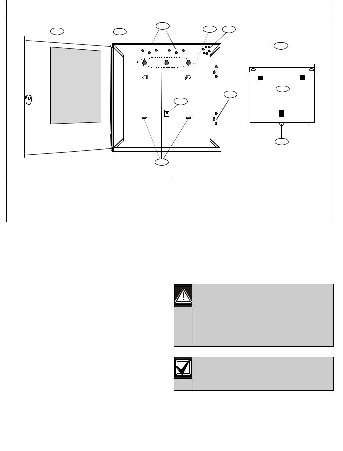
Figure 2: |
Enclosure Mounting |
|
|
|
|
|
1 |
2 |
3 |
2 |
4 |
|
|
||||
|
|
|
|
||
|
|
|
|
|
7 |
|
|
|
|
|
8 |
|
|
|
|
|
3 |
|
|
|
|
5 |
|
|
|
|
|
|
9 |
|
|
|
6 |
|
|
1 - |
Point chart label |
6- |
Enclosure mounting holes (5) |
2 - Mounting skirt hooks (2) |
7 - |
Mounting skirt hook holes (2) |
|
3 - Module mounting holes (12) |
8 - |
Back of D9412GV3/D7412GV3 Control Panel |
|
4 - Tamper switch mounting holes (5) |
9 - |
Lock down tab |
|
5 - |
Skirt mounting hole (1) |
|
|
4.4Installing the Control Panel
1.Place the control panel over the inside back of the enclosure, aligning the large rectangular openings of the mounting skirt with the mounting hooks of the enclosure. Slide the control panel down so that it hangs on the hooks. Refer to Figure 2, Item 2 on page 15.
2.Remove the tape from the #6 x 1/4-in. screw in the mounting tab on the control panel. The screw passes through the mounting tab and into the skirt mounting hole in the enclosure. Tighten the screw to secure the control panel in the enclosure.
3.Connect earth ground to the control panel before making any other connections. Refer to Section 4.5 Connecting Earth Ground.
4.5Connecting Earth Ground
4.5.1Terminal 10
To help prevent damage from electrostatic charges or other transient electrical surges, connect the system to earth ground at Terminal 10 before making other connections. Recommended earth ground references are a grounding rod or a cold water pipe.
Caution: Do not use telephone or electrical ground for the earth ground connection. Use
1.8 mm (14 AWG) to 1.5 mm (16 AWG) wire when making the connection.
Do not connect other control panel terminals to earth ground.
4.5.2Ground Fault Detect Enable
To meet UL 864 requirements, enable
Ground Fault Detect.
A ground fault is a circuit impedance to earth ground. The control panel has a ground fault detection circuit that, when enabled, detects ground faults on Terminals 1 to 9 and 11 to 32. The control panel also detects and annunciates ground faults on any device connected to it.
Bosch Security Systems, Inc. | 10/10 | F01U143070-03 |
15 |

D9412GV3/D7412GV3 | Operation and Installation Guide | |
4.0 |
Installation |
|
|
|
If a ground fault condition occurs, the keypads display SERVC GND FAULT and the control panel transmits a GROUND FAULT TROUBLE, AREA 1.
When the control panel recognizes that the ground fault condition is corrected, and remains corrected for between 5 to 45 consecutive sec, a Restoral Report is sent.
The D9412GV3 and D7412GV3 Control Panels log and print a Ground Fault event as a Trouble Point 256 if communicating in Modem IIIa2 format. If communicating in Contact ID format, the control panels generate a Ground Fault (310) event.
4.5.3Enabling Ground Fault Detection
To enable Ground Fault Detect Enable, lock (close) the S4 Ground Fault Detect Pin on the control panel (Figure 3).
Figure 3: Enabling Ground Fault Detection
|
|
|
F01U14307402 |
|
|
|
|
|
|
|
|
|
|
|
|
|
|
|
|
|
|
|
|
ncoI |
rect |
wi ring w li l |
|
|
|
|
|
|
|
|
WARNING ! |
|
|||
|
|
|
|
damage th si equi pment . |
|
|
|
|
|
|
|
|
|
||||||
|
|
|
|
|
|
|
|
|
|
|
|
|
|||||||
|
|
|
|
S ui ablt e of rdry ndi |
oor |
|
|
|
|
|
|
|
|
To preven t risk of |
|
||||
|
|
|
LE Ds O f Wh enN ormal |
u seo nly. |
|
|
|
|
|
D9412GV3 |
el ect ri c shock, |
|
|||||||
|
|
|
|
Devi ces pow ered byt he |
|
|
|
di sconn ect AC po wer |
|
||||||||||
|
|
|
|
|
|
|
and t el ephon el in es |
|
|||||||||||
|
|
|
|
AUX p ower out put |
mu st |
|
|
|
bef ore servic ing . |
|
|||||||||
|
|
|
|
bes upervi sed. |
|
|
|
|
|
|
|
|
|||||||
|
|
|
10. 2V DC - B at tery Loa dS hed |
|
|
|
|
|
Co mmerci al Prot ect edPremis esC ont rol Pa nel |
|
SDI Conn ect or |
|
|||||||
|
|
|
YE LLO W- C hargi ng St atu s |
R efer ot t he D94 12GV 3/D 7412G V3 Ap proved App li cat ion sC ompl ani ceG ui de P( N/ : F01U 143069) |
|
Re set Pi n |
|
||||||||||||
|
|
|
|
|
|
of |
rSy stem Wiri ng Di agram, ssI ueA an df or |
compat bi |
el smoke det ect ors. |
D isab le Al l Exc ept B atReeryset Pi n |
|
||||||||
|
|
|
|
|
|
M ni mum syst em eqr uirement sf orCl assif cati oni ni |
accordancew ti hAN SI/ SI ACP 01- - 2000: |
D isab le Al l ExcR eseptt PBni at ery |
|
||||||||||
|
|
|
|
|
|
UL List ed andCl assif edi |
cont olr uni t Mo del D9412GV3, D7412G V3, orD7212G V3; |
C hargin gA nd Prog ar mmi ng |
|
||||||||||
|
|
|
RED - Low B at tery - 12. 1 VDC |
|
D isabCh arginle al lgexceptA nd ProgBat tammirery ng |
|
|||||||||||||
|
|
|
|
|
|
UL List ed andCl assif edi |
keypadM odel D1256, D1257, D1260, D 1255,D 1255R, orD1255RW; |
Ch argin gan dP rogramming |
|
||||||||||
|
|
|
|
|
|
UL List ed Local Bel |
|
|
|
|
|
|
|
|
|
|
|||
|
|
|
|
|
|
|
|
|
|
PO WER S UPP LY REQ UI RE ME NTS |
|
PERI PHER AL DEVI CE CON NECTI ONS |
|
|
|||||
|
|
|
CLAS S2 TRAN SFORM ER |
|
|
T heP ow erSu ppl yp or vide sa maxi mu m of 1. 4 Amps fo rt he Cont rol P anel an dal l |
RED |
P OWER + |
|
|
|||||||||
|
|
|
Model165. VACD 164040VA 60H z |
|
|
A ccesso yr |
D evice s. For |
Syst emL oadi ng, ref ert o ht eD 9412G V3/ D74 12GV 3O perat io n |
|
|
|||||||||
|
|
|
ntI ernal yFused - Do not short |
|
an dI nst al atl i on Gui de ( P/N : F0 1U1430 70). |
|
|
|
|
|
|
|
|||||||
|
|
|
Requi esr Unswi t chedO utl et |
|
A l exte rn al conn ect oni |
sexc ept Termi nal |
5 b( at ery posi t ve)i |
are i nherent l yp ower |
YELLO W |
DATA BU SA |
|
|
|||||||
|
|
|
Do not sharewi ht ot herequi pment |
l i mi t ed. Re qui emenr |
ts f orba t erys tan dby it memi ght red uce al ow abl eou pt ut. |
|
|||||||||||||
|
|
|
+A UX P OWER |
|
|
CA UTIO N: Ref ert o ht eD 9412G V3/ D741 2GV 3O perat io nan dI nst al atl i on Gui de |
GR EEN |
DATA BU SB |
|
||||||||||
|
|
|
|
|
|
( P/ N: F01U1 43070) f or Pow erRe qui emenr |
ts relat in gt o Terminal s 6 an d 7 . |
|
|
|
|
||||||||
BA TTER Y NEG AT VEI |
O NLY |
WARNING! |
|
|
|
i on re qu resi |
|
B at t ery: R epl ac e every 3 t o |
|
|
BLAC K |
C OM MON |
|
|||||||||||||||||||
CA UTI ON : Avoi ddamaget o Panel. |
M u tl i - Ba t e yr i n st al atl |
|
|
|
|
|||||||||||||||||||||||||||
Do not connect 24V t ot ermi nals. |
M o de l D 122/ D 122 L Du al Ba t ery |
|
|
5 y ears w i ht |
o ne o rt w o M od el |
|
|
|
|
|
|
|
|
|||||||||||||||||||
Max imumch argin gcu rent |
14. A |
H arn ess . I mpro per ni |
st al l at io n can |
|
D 12 6 or |
D1 218 12 V Le ad A ci d |
|
N. FP. . A. |
|
ZON EXO UT 1 |
|
|||||||||||||||||||||
BAT TER Y POS TI VEI |
O NLY |
|
b e a f rei |
h azard . |
|
|
|
|
|
|
|
B at t eri es. |
|
|
|
|
|
|
|
|||||||||||||
|
|
|
|
|
|
Thi sequi pment should bei nstal edl |
ni accordancew ti ht heN FPA70 (N ati onal Elect rical Code) and |
|
St yle |
40. |
|
|
|
|
||||||||||||||||||
REL AY |
A |
PR OG R AM MA BLE |
|
Si gnali ng |
|
|
2727 |
|||||||||||||||||||||||||
NF PA72 (N ati onal FireA larmCode) f orLocal , Cent alr St ati on, Propriet ary andH ousehold Fire Warning |
|
Li ne |
ti s |
|
ZON EXI N 1 |
|||||||||||||||||||||||||||
|
|
A LAR M O UTP UTS |
Syst ems and underht |
eil mit sof t heLocal A uthorit y Having Jurisdi cti on( Nat onali |
Fi er |
P otr |
ecti on |
|
Ci cur |
|
|
|||||||||||||||||||||
|
|
|
Terminal s |
|
Asso ci at on,i |
Bat t ermarch Park, Qui ncy,M A |
02269). Print ed nfi ormat ion descri bing properi nstal atl ion, |
|
|
|
|
|
|
|
2626 |
|||||||||||||||||
REL AY |
B |
|
6 |
and 7 |
|
operat on,i |
t esti ng, mai nt enance, evacu ati onpl anning and epair |
rservicei st obe provi dedw ti ht hi s |
|
|
|
|
|
ZON EX OUT 2 |
||||||||||||||||||
|
|
SWI TCH ED A UX |
equi pmen .t |
|
|
|
|
|
|
|
|
|
|
|
|
|
|
|
|
|
|
|
|
|
|
|
|
|
26 |
|||
|
|
D 9412G V3C ontrol Panel si |
ULL sti ed ForCent ral Stat on,i |
Local , Auxil ary,i |
Propri etary,and Househol d |
|
|
|
|
|
|
|
2525 |
|||||||||||||||||||
REL AY C |
|
Termi nal |
8 |
Fi er Al arm, andCent ralS at on,i |
Local , Poli ceSt ati onCo nnect, Househol dB urgl arAl rmandEncrypt ed |
|
|
|
|
|
ZON EX IN 2 |
|||||||||||||||||||||
|
Li neSecuri ty whencommunicat ing via anet work. |
|
|
|
|
|
|
|
|
|
|
|
|
|
5 |
|||||||||||||||||
|
|
|
|
|
|
S yst emi si ntended ot |
be checkedby aQ uali if edTechni cian at eastl |
every3 years. |
|
|
|
|
|
|
ZO NEX POWER + |
24 |
||||||||||||||||
C OM M ON |
|
|
|
|
Th et ypesof i nit ati |
ngi |
ci cuir |
st |
het |
cont olr panel has been approved f orare A, M , W,SS. |
|
|
|
|
|
|||||||||||||||||
|
|
|
|
Th et ypesof si gnali ngt he control panel has beenapproved orf |
are DAC, O T, NC |
|
|
|
|
|
|
|
|
2 |
|
24 24 |
||||||||||||||||
EAR TH G RO UND |
|
|
|
|
|
|
|
|
|
|
|
|
O pen |
|
|
|
|
V OLTA GE R AN GE S |
|
S hort |
00.ZO1NEX. 3 VDCCOM MO N |
23 |
||||||||||
|
|
|
|
|
|
|
|
|
|
|
|
|
|
|
|
|
|
|
3. 7 - 5. 0V DC |
|||||||||||||
|
|
|
|
|
|
|
|
|
|
|
|
|
|
|
|
N ormal |
|
|
|
|
|
|
2. 0 - 3. 0V DC |
|
|
|
|
|
|
|||
S4 GR OUND FAU LTD ETECT |
|
|
Poin t 1 Poi nt 2 |
|
|
Poi nt 3 P oint |
4 |
Poi nt 5 Po nti 6 |
P oint |
7 Poi nt 8 |
|
Po nti |
8, S3 Op it on |
D5200/D |
5360PRO G |
|||||||||||||||||
Enabl de |
|
|
|
|
|
|
|
|
|
|
|
|
|
|
|
|
|
|
|
|
|
|
|
|
Cl osed= 1k EO L |
PRO GC ONNCO NN |
||||||
Di sabled |
|
|
|
|
|
|
|
|
|
|
|
|
|
|
|
|
|
|
|
|
|
|
|
Normal O perat io n |
|
PR OG |
||||||
PHONE LINE |
SEIZED |
LED |
|
|
|
|
|
|
|
|
|
|
|
|
|
|
|
|
|
|
|
|
|
Open =AB12 UL |
|
|
C ONN |
|||||
|
|
|
|
|
|
|
|
|
|
|
|
|
|
|
|
|
|
|
|
|
Bel l Box220 k |
|
|
|
||||||||
ON whencommunicati ng |
|
|
|
|
|
|
|
|
|
|
|
|
|
|
|
|
|
|
|
|
|
Operat ion Moni ot |
rLED |
|
|
|||||||
OFFw hen dli |
e |
|
|
|
|
|
|
|
|
|
|
|
|
|
|
|
|
|
|
|
|
|
|
|
|
|||||||
|
|
|
|
R IN G |
|
|
|
|
|
|
|
|
|
|
|
|
|
|
|
|
|
|
|
|
Pul seswhen Normal |
|
|
|||||
|
|
ITP |
11 |
12 |
13 |
14 |
15 |
16 |
17 |
18 |
19 |
20 |
|
21 |
22 |
|
Fli ckerswhen Ri nging |
|
|
|||||||||||||
|
|
|
|
|
G R E E N |
|
|
|
|
|
|
|||||||||||||||||||||
RED T E L C O C O R D |
MO D E L D 1 61 |
|
|
|
|
|
|
|
|
|
|
|||||||||||||||||||||
1 - S4 Locked (Closed). Control panel detects ground faults.
2 - S4 Unlocked (Open). Control panel does not detect ground faults.
4.5.4Ground Fault Specifications
Table 5 provides the impedance specifications for detecting ground faults when any terminal or field wiring is shorted to ground.
Table 5: Ground Fault Impedance
Specifications
|
|
|
|
|
|
Impedance |
Control Panel Detects Ground Fault |
|
|
|
≤ 300 Ω |
|
Yes |
|
|
300 Ω to |
|
Detection depends upon the terminal |
|
|
200 kΩ |
|
|
|
|
|
|
|
|
|
≥ 200 kΩ |
|
No |
|
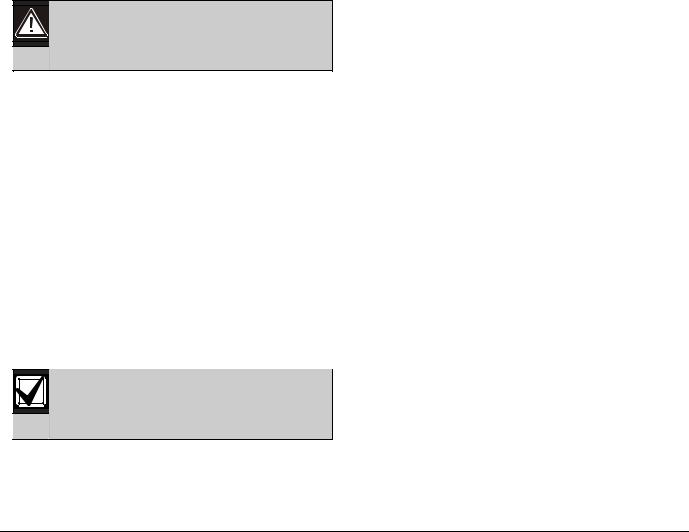
4.5.5Locking the Reset Pin
Locking the reset pin disables the control panel (Figure 4). When the control panel is disabled, the system ignores most keypad commands and points. CALL FOR SERVICE appears in keypad displays when the pin is locked down.
On-board relays (Terminals 6 and 7) and off-board relays deactivate when the control panel is reset. Terminal 8 has power when the relay is deactivated. Activation interrupts power at that terminal. The onboard relay (Terminal 8) remains deactivated when the reset pin is locked in the disable position.
Releasing the reset pin from the closed position resets the control panel. The control panel resets all its timers, counters, indexes, and buffers. Any points that restore after a reset do not generate Restoral Reports.
If the reset pin is placed in the disable position when all areas are armed, there must be an entry in the Answer Armed program item. Refer to RPS Parameters in the D9412GV3/D7412GV3 Program Entry Guide (P/N: F01U170807).
Locking the pin in the disable position applies power to the control panel and charges the battery while the detection devices and keypads are installed.
Figure 4: Reset Pin
1 - Reset pin locked (closed)
2 - Reset pin normal (open)
Bosch Security Systems, Inc. | 10/10 | F01U143070-03 |
16 |
D9412GV3/D7412GV3 | Operation and Installation Guide | |
4.0 |
Installation |
|
|
|
4.6Completing the Installation
If not already complete, make the earth ground connection to Terminal 10 and lock the reset pin in the closed position.
4.6.1Charging the Battery
Connect the battery, then the transformer to allow the control panel to charge the battery while you complete the installation. Refer to Section 5.0 Power Supply on page 22 for instructions.
On-board Buzzer Sounds at Power Up and Reset:
The system performs a series of self-diagnostic tests of hardware, software, and programming at power up and at reset. The buzzer on the control panel sounds during the tests. The self-diagnostics tests complete in approximately 1 to 3 sec.
If the control panel fails any test, the buzzer continues sounding and a System Trouble message appears at the keypads.
Touch Terminal 10 First: If the on-board buzzer sounds briefly when the control panel is touched, any static charge you carry discharges to the control panel.
Avoid electrostatic discharge. Always touch Terminal 10, the earth ground connection, before beginning work on the control panel.
If the control panel receives an electrostatic discharge, it might generate Watchdog Reset and Param Fail events.
4.6.2Installing and Wiring Detection Devices
Install and wire detection devices and keypads at their locations throughout the premises. Do not connect the control panel yet.
Section 8.0 On-Board Points on page 31 contains instructions for wiring the on-board points to detection devices. Section 11.0 Arming Devices on page 55 contains instructions for wiring the keypads.
Instructions for wiring the off-board point POPIT sensor loops are found in the instructions packaged with the POPIT modules.
4.6.3Installing Modules and Relays
1.Power down the unit by unplugging the transformer and disconnecting the battery.
Always power down the unit when installing modules or relays, or when making wiring connections to the control panel.
2.Install and wire any modules required for the installation as described in the module’s installation instructions.
Instructions for the D8125 POPEX Module, D8128D OctoPOPIT Module, D8129 OctoRelay Module, D811 Arm Status Relay Module, and D928 Dual Phone Line Switcher appear in this guide.
Refer to Section 9.0 Off-Board Points on page 36 for D8125 and D8128D instructions. Refer to
Section 10.0 Off-Board Relays on page 50 for D8129 and D811 instructions. Refer to Section 7.11 D928 Dual Phone Line Switcher on page 30 for D928 instructions.
3.If using the power outputs at Terminals 7 or 8, refer to Section 6.4 Programmable Power Output Terminals 6, 7, and 8 on page 27 for instructions.
4.6.4Connecting the On-board Points and Keypads
4.Connect the on-board points and keypad wiring to the system. Refer to Section 8.0 On-Board Points on page 31 and Section 11.0 Arming Devices on page 55 for instructions.
4.6.5Powering Up
Reconnect the battery, then plug in the transformer. The buzzer sounds for two sec when the control panel is powered up. Leave the reset pin in the locked position.
Yellow Charging Status LED Remains Lit: If the yellow charging status LED remains lit after five minutes of powering up the control panel, either the battery is deeply discharged or too many powered devices were connected to the control panel. Combined continuous current draw for Terminals 3, 8, 24, and 32, and the accessory connector cannot exceed 1.4 A. Refer to Section 6.0 Power Outputs on page 26 for help.
4.7Programming the Control Panel
If the control panel is not already programmed, review the D9412GV3/D7412GV3 Program Entry Guide
(P/N: F01U170807). Ensure that all accessory modules for desired features are available for installation.
Use RPS to load a custom program into the control panel as needed.
Bosch Security Systems, Inc. | 10/10 | F01U143070-03 |
17 |

D9412GV3/D7412GV3 | Operation and Installation Guide | |
4.0 |
Installation |
|
|
|
4.8Installing the Point Chart Label
The point chart label is required for fire systems with verifications points.
A point chart label is included in the literature pack. Install the point chart label for fire or combined fire- and-burglary systems that use verification points.
Use the D9412GV3/D7412GV3 Program Record Sheet (P/N: F01U170809) to gather the necessary information for completing the point chart. Fill out the label and install it on the inside of the enclosure door (refer to Figure 2 on page 15).
Avoid smearing the entries on the chart. Use the peel-off backing to press the label in place.
4.9Testing the System
After installing and programming the control panel, test the system completely. Test the control panel and all devices for proper operation.
Test after initially programming the control panel.
To meet UL 864 requirements, perform a full system test after any subsequent programming session.
Refer to Section 4.10 Service Walk Test on page 18 for complete Service Walk Test instructions.
Clear after Test: To clear the event memory and report buffer, momentarily close the reset pin. Events stored in the control panel’s event log are not cleared.
4.10Service Walk Test
The Service Walk Test differs from the standard Walk Test. In the standard Walk Test, POPITs whose switches are set for a point number not programmed in the control panel do not appear in the test. In the Service Walk Test, POPITs whose switches are set for a point number that is not programmed in the control panel do appear in the test.
The Service Walk Test allows a user to walk test all 246 points from a control-panel-wide keypad, regardless of the point index type.
A Service Walk Test can also be initiated by accountwide or area-wide keypads but test only those points that are within the scope of the keypad that initiated the function. The Service Walk Test does not test points in armed areas.
Only Walk Test Start and Walk Test End are reported to the central station.
The D9131A can be configured for local printing. Refer to the D9412GV3/ D7412GV3 Program Entry Guide
(P/N: F01U170807).
During a Service Walk Test, the summary alarm and summary fire remain off, because there are no Fire or Burg alarm conditions to summarize. The P# Relay Response Type feature operates as programmed.
Service Walk Test Procedure.
Refer to Figure 5 on page 20 and Figure 6 on page 21 for Service Walk Test options. Refer to the Walk Test procedures in the GV3 Series Owner’s Manual Supplement (P/N: F01U143082) when using a D1260 or D1260B Keypad.
1.Choose a keypad to conduct the test. Ensure that the display shows the idle disarmed text.
2.Press the [MENU] key to enter the Function List. Press [NEXT] repeatedly until the SERVICE WALK ? prompt appears.
3.Press [ENT], or press [9][9] followed by [ENT] to reach the Service Menu to access the Service Walk Test.
The D7412GV3 does not include the Service Walk Test in the Service Menu. Enabling the Service Walk Test function in the Function List provides access to the Service Walk Test in the D9412GV3.
4.The display shows ### PTS TO TEST .Test the first detection device.
5.When a detection device is faulted, the keypad emits a brief tone and displays the point text of the point tested for 60 sec. After 60 sec, the display returns to the ### PTS TO TEST message.
Extra Points display default text: If the switches on a POPIT are set incorrectly to a point number that is not in the program for the control panel, the default text for that point number (PT ###) appears when the point is faulted. Refer to the control panel’s program record sheet for the default text for all points.
Faulting the point a second time produces the tone and shows the point text, but does not decrease the count in the ## PTS TO TEST message.
Bosch Security Systems, Inc. | 10/10 | F01U143070-03 |
18 |

D9412GV3/D7412GV3 | Operation and Installation Guide | |
4.0 |
Installation |
|
|
|
5.To see the points that remain untested during the Service Walk Test:
a.Press [ESC] when point text appears. The display shows ## PTS TO TEST.
b.Press the [ESC] key. VIEW UNTESTED ? appears.
c.Press [ENT]. ## PTS UNTESTED appears.
d.Press [NEXT] to see a list of the points that have not yet been tested. Move through this list by pressing the [NEXT] key.
e.To resume the Service Walk Test, press [ESC]. ## PTS UNTESTED appears.
f.Press [ESC]. ## PTS TO TEST appears.
g.Resume testing points. To end the Service Walk Test, press [ESC] twice.
6.After the last point is tested, 0 PTS TO TEST appears. Press [ESC]. The display shows ALL PTS TESTED briefly before returning to idle text.
The Service Walk Test, when performed on a D7412GV3, cannot display “0 PTS TO TEST” because the D7412GV3 is physically unable to connect to the second POPEX Module (used for Points 129-247).
Automatic time-out returns the system to idle text: If there is no point or keypad activity for 20 min., the Service Walk Test ends automatically. The keypad returns to idle text.
Bosch Security Systems, Inc. | 10/10 | F01U143070-03 |
19 |
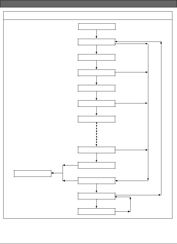
|
D9412GV3/D7412GV3 | Operation and Installation Guide | 4.0 |
Installation |
|
Figure 5: D9412GV3 Service Walk Test Flow Chart |
|
|
|
|
SERVICE WALK? |
|
|
|
[ENT] |
|
|
|
246 PTS TO TEST |
[ESC] |
|
|
Test a device |
|
|
|
|
|
|
|
POINT TEXT |
|
|
|
(Text displays for 60 seconds) |
|
|
|
245 PTS TO TEST |
[ESC] |
|
|
Test a device |
|
|
|
POINT TEXT |
|
|
|
(Text displays for 60 seconds) |
|
|
|
244 PTS TO TEST |
[ESC] |
|
|
|
|
|
|
Test a device |
|
|
|
POINT TEXT |
|
|
|
1 PTS TO TEST |
[ESC] |
|
|
Test a device |
|
|
|
|
|
|
|
0 PTS TO TEST |
|
|
IDLE TEXT |
[ESC] |
|
|
|
VIEW UNTESTED? |
|
|
|
[ENT] |
|
|
|
# PTS UNTESTED |
|
[ESC] |
|
[NEXT] |
[ESC] |
|
|
POINT TEXT |
|
|
Bosch Security Systems, Inc. | 10/10 | F01U143070-03 |
|
20 |
|
|
D9412GV3/D7412GV3 | Operation and Installation Guide | 4.0 |
Installation |
|
Figure 6: D7412GV3 Service Walk Test Flow Chart |
|
|
|
|
SERVICE WALK? |
|
|
|
[ENT] |
|
|
|
75 PTS TO TEST |
[ESC] |
|
|
Test a device |
|
|
|
|
|
|
|
POINT TEXT |
|
|
|
(Text displays for 60 seconds) |
|
|
|
74 PTS TO TEST |
[ESC] |
|
|
Test a device |
|
|
|
POINT TEXT |
|
|
|
(Text displays for 60 seconds) |
|
|
|
73 PTS TO TEST |
[ESC] |
|
|
|
|
|
|
Test a device |
|
|
|
POINT TEXT |
|
|
|
1 PTS TO TEST |
[ESC] |
|
|
Test a device |
|
|
|
|
|
|
|
0 PTS TO TEST |
|
|
IDLE TEXT |
[ESC] |
|
|
|
VIEW UNTESTED? |
|
|
|
[ENT] |
|
|
|
# PTS UNTESTED |
|
[ESC] |
|
[NEXT] |
[ESC] |
|
|
POINT TEXT |
|
|
Bosch Security Systems, Inc. | 10/10 | F01U143070-03 |
|
21 |
|
D9412GV3/D7412GV3 | Operation and Installation Guide | |
5.0 |
Power Supply |
|
|
|
5.0Power Supply
5.1Primary Power Terminals 1 and 2
5.1.1Primary (AC) Power Circuit
The primary source is a 16.5 VAC, 40 VA, internallyfused transformer (Bosch Security Systems, Inc. Model D1640). The control panel draws 200 mA when idle and 300 mA when in an alarm state. The total available auxiliary current is 1.4 A.
Transient suppressors and spark gaps protect the circuit from power surges. This protection relies on the ground connection at Terminal 10. Ensure that you connect Terminal 10 to a proper ground. Refer to
Section 4.5 Connecting Earth Ground on page 15.
AC Power Fail
The system indicates an AC power failure when Terminals 1 and 2 do not have power. The AC Fail Time parameter sets the number of minutes or seconds without AC power before the control panel acknowledges the failure and the number of minutes or seconds after the power returns before the control panel acknowledges restored power. Refer to the
D9412GV3/D7412GV3 Program Entry Guide
(P/N: F01U170807) for additional information about AC Fail Time and UL 864 requirements.
5.1.2Installing the Transformer
Do not short-circuit the terminals of the transformer: Shorting the terminals opens the internal fuse, causing permanent failure. Connect the transformer to Terminals 1 and 2 of the control panel before plugging it into the power source.
1.Use 1.22 mm (18 AWG) wire (minimum) to connect the transformer to the control panel.
The wire length should be as short as possible. The maximum length is 15 m (50 ft). Connect the battery and plug in the transformer.
2.Route telephone and sensor loop wiring away from any AC conductors, including the transformer wire.
AC wiring can induce noise and low level voltage into adjacent wiring. Route data wiring away from AC and telephone wiring.
Always connect the battery first and then plug in the transformer.
3.Connect the battery. Refer to Section 5.2.2 Installing the Battery on page 22.
4.Plug the transformer into an unswitched, 120 VAC, 60 Hz power outlet only.
5.Secure the transformer to the outlet with the screw provided.
D8004 Transformer Enclosure Required for Fire Systems
Use the D8004 Transformer Enclosure for the D1640 Transformer in fire and combined fire and burglary applications.
Check with the Authority Having Jurisdiction (AHJ) about mounting transformers on specific circuits.
5.2Secondary Power Terminals
5.2.1Secondary (DC) Power
A 12 V sealed lead-acid rechargeable battery (D126) supplies secondary power for auxiliary and alarm outputs, and powers the system during interruptions in primary (AC) power.
Use Lead Acid Batteries Only: The charging circuit is calibrated for lead-acid batteries. Do not use gel-cell or nicad batteries.
Extra Batteries Increase Back-up Time
To increase battery back-up time, connect a second 12 V battery in parallel to the first battery. Use a D122 Dual Battery Harness to ensure proper and safe connection. Refer to the Standby Battery and Current Rating Chart in the D9412GV3/D7412GV3 Approved Applications Compliance Guide (P/N: F01U143069) for battery standby time calculations.
D1218 Battery
The D1218 is a 12 V, 18 Ah battery for use in applications requiring extended battery standby time. Up to two D1218 batteries can be connected when used with a D122 Dual Battery Harness.
Caution: When connecting two D1218 Batteries to the control panel, both must have the same capacity (use two 17.2 Ah batteries or two 18 Ah batteries).
When using two D1218 batteries, use a separate enclosure, a D122L Dual Battery Harness, and long leads.
5.2.2Installing the Battery
1.Place the battery upright in the base of the enclosure.
2.Locate the red and black leads supplied in the literature pack.
Bosch Security Systems, Inc. | 10/10 | F01U143070-03 |
22 |
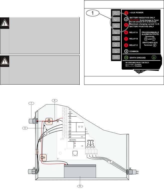
D9412GV3/D7412GV3 | Operation and Installation Guide | |
5.0 |
Power Supply |
|
|
|
3.Connect the black battery lead to Terminal 4, and then to the negative (-) side of the battery.
4.Connect the red battery lead to Terminal 5, and then to the positive (+) side of the battery.
Warning: High current arcs are possible. The positive (red) battery lead and Terminal 5 can create high current arcs if shorted to other terminals or the enclosure. Use caution when working with the positive lead and Terminal 5. Always disconnect the positive (red) lead from the battery before removing it from Terminal 5.
Caution: The battery terminals and wire are not power limited. A 6.4 mm (0.250 in.) space must be maintained between the battery terminals, battery wiring, and all other wiring. Battery wiring cannot share the same conduit, conduit fittings, or conduit knock-outs with other wiring.
Figure 7: Battery Terminals
1 - Battery terminals. Terminal 5 is non-power limiting.
|
Figure 8: Non-Power-Limited Wiring |
|
|
|
|
|
|
|
|
|
|
|
|
|
|
1 - Conduit required for use with external batteries. |
4 - |
Relay output wires |
|
|
2 - Battery wires |
5 - Input or Zone wires |
|
|
|
3 - 6.4 mm (0.25 in.) minimum. To ensure proper |
6 - |
Standby battery |
|
|
spacing, use tie-wraps or similar devices to |
|
|
|
|
secure wires. |
|
|
|
|
|
|
|
|
|
Bosch Security Systems, Inc. | 10/10 | F01U143070-03 |
|
23 |
|
 Loading...