


CCS 800 Ultro
|
|
|
|
|
|
|
|
|
|
|
|
|
|
|
|
|
|
|
|
|
en |
|
Installation and Operating Manual |
|
|
|
|
|
|
|
|
|
|
||
|
|
|
|
|
|
|
|
|
|
||
|
|
|
|
|
|
|
|
|
|
||
|
|
|
|
|
|
|
|
|
|
||
|
|
|
|
|
|
|
|
|
|
||
|
|
|
|
|
|
|
|
|
|
||
|
|
|
|
|
|
|
|
|
|
Discussion System |
|
|
|
|
|
|
|
|
|
|
fr |
|
Manuel d’installation et d’utilisation |
|
|
|
|
|
|
|
|
|
|
||
|
|
|
|
|
|
|
|
|
|
Système de Discussion |
|
|
|
|
|
|
zh-t |
|
|
|
de |
|
Installationsund Bedienungshandbuch |
|
|
|
|
|
|
|
|
|
|||
|
|
|
|
|
|
|
|
|
Diskussionssystem |
||
|
|
|
|
|
zh-s |
|
|
|
es |
|
Manual de instalación y funcionamiento |
|
|
|
|
|
|
|
|
|
|||
|
|
|
|
|
|
|
|
|
Sistema de Conferencias |
||
|
|
|
|
|
th |
|
|
|
nl |
|
Installatieen gebruikshandleiding |
|
|
|
|
|
|
|
|
|
|||
|
|
|
|
|
|
|
|
|
Discussiesysteem |
||
|
|
|
|
|
ja |
|
|
|
it |
|
Installazione e Manuale operativo |
|
|
|
|
|
|
|
|
|
|||
|
|
|
|
|
|
|
|
|
Sistema audio congressuale |
||
|
|
|
|
|
|
|
|
|
|
|
|
Page
en............................................................................................. |
3 |
Prior to installing or operating this product always read |
|
|
the Safety Instructions which are available as a separate |
|
|
document. |
fr ............................................................................................ |
24 |
Avant d 'installer ou d'utiliser ce produit, lisez toujours |
|
|
les Instructions de sécurité disponibles dans un docu- |
|
|
ment distinct. |
de ......................................................................................... |
46 |
Lesen Sie vor Installation oder Inbetriebnahme dieses |
|
|
Produkts in jedem Fall die Sicherheitshinweise, die als |
|
|
gesondertes Dokument vorliegen. |
es ........................................................................... |
68 |
Antes de la instalación o utilización de este producto lea |
|
|
las Instrucciones de seguridad disponibles en un docu- |
|
|
mento independiente. |
nl ............................................................................ |
90 |
Lees voor installatie of gebruik van dit product eerst de |
|
|
Veiligheidsvoorschriften die in een apart document |
|
|
staan. |
it ............................................................................ |
112 |
zh-t...................................................................... |
134 |
zh-s..................................................................... |
155 |
th.......................................................................... |
176 |
ja .......................................................................... |
198 |
Prima di installare o mettere in funzione questo prodotto, leggere sempre le Istruzioni di sicurezza, che vengono fornite in un documento separato.

CCS 800 Ultro | Installation and Operating Manual |
en | 5 |
|
|
1 About this manual 2 Introduction
This "Instructions For Use" manual provides all the information required to install and operate the CCS 800 Ultro Discussion System.
Conventions
Warning
Warnings draw attention to instructions that must be followed to prevent personal injury.
Caution
Cautions draw attention to instructions that must be followed to prevent damage to the equipment.
Note
Notes draw attention to special instruction tips or other useful information.
The CCS 800 Ultro Discussion System is a discussion system for use in meeting and conference venues with a limited number of participants.
A CCS 800 Ultro Discussion System consists of:
•One Control and Power Supply Unit (CPSU).
•Maximum 50 units of which one or more chairman unit(s).
•Extension cables if required (5m or 10m).
•Peripheral audio and/or telecommunication equipment.
The CPSU is the heart of the discussion system which controls the microphones of the chairman and delegate units as well as providing facilities for audio inputs and outputs. It also supplies the power for the CPSU itself, chairman unit(s) and delegate unit(s).
With the use of Digital Acoustic Feedback Suppression the loudspeaker volume can be increased significantly before feedback appears. Digital Acoustic Feedback Suppression is only available in LBB 3310/10.
A delegate unit enables participants to actively join in a discussion (i.e. speaking and listening) by means of a microphone, controlled by an on/off button and
a built-in loudspeaker or external headphone.
A chairman unit has the same function as a delegate unit with the addition of a 'Priority' button, that enables its operator to control the debate by temporary or permanently overruling and muting all active microphones, depending on an internal setting in the chairman unit.
Bosch Security Systems | 2003-06 | 3922 988 54284
CCS 800 Ultro | Installation and Operating Manual |
en | 6 |
|
|
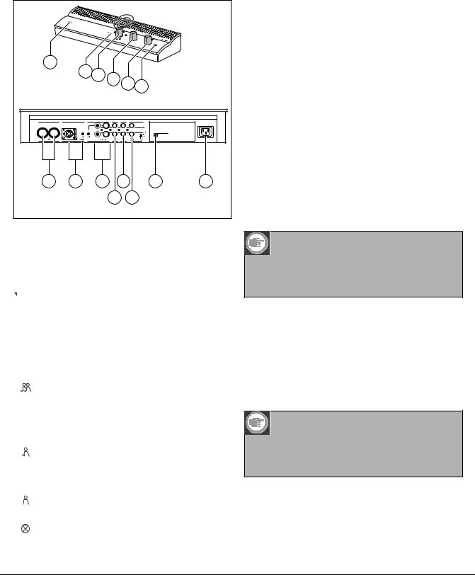
3Control and power supply unit (CPSU)
|
|
CC |
|
|
|
|
|
|
|
|
|
|
S 800 |
ULTRO |
|
|
|
|
|
|
|
|
|
|
|
|
|
|
|
|
|
|
1 |
|
|
2 |
|
|
|
|
|
|
|
|
|
|
3 |
4 |
|
|
|
|
|
|
|
|
|
|
|
5 |
|
|
|
||
|
|
|
|
|
|
6 |
|
|
||
|
|
|
|
|
|
|
|
|
||
|
|
|
|
|
|
|
|
|
|
|
Trunk in/out |
Microphone |
|
Recorder |
|
Line |
Telephone Insertion |
|
|
|
|
|
|
|
|
|
|
|
|
In |
|
|
|
|
|
Gain Gain |
|
|
|
|
Out |
Digital Acoustic |
|
|
|
|
|
|
|
|
|
Feedback Suppression |
|
|
|
|
|
|
|
|
|
|
|
|
90-260 V~ |
7 |
|
8 |
9 |
|
11 |
|
13 |
14 |
||
|
|
|
|
|
10 |
12 |
|
|
|
|
Figure 3.1
1 Mains On/Off switch.
2 Power On LED indicator (green).
3 Microphone-mode switch.
Open mode with auto switch-off. To select 
 the maximum number of delegate microphones
to be activated simultaneously (1, 2, 3 or 4). The microphone automatically switches off if the speaker does not speak for 30 seconds.
The microphone can manually be switched off by pushing the button on the delegate unit. Open mode. To select the maximum number
of delegate microphones to be activated simultaneously (1, 2, 3 or 4). The microphone must be switched on or off manually by pushing the button on the delegate unit.
Override mode. Only one delegate
microphone can be activated. If a new delegate presses his microphone button, the microphone unit of the current speaker will be switched off.
Chairman only mode. Only the chairman units can be activated.
Test mode. For proper installation check. All the light-rings and LED's of the connected
units will lit, if properly connected.
4 Speaker volume control of all connected delegate and chairman units.
5Volume control of the speaker or headphone of the CPSU.
6Headphone connection with 3.5 mm stereo jackplug socket.
7Trunk output 1 and 2. For loopthrough connection of the delegate and chairman units. To each output a maximum of 25 units can be connected.
The maximum length of cable between the outputs of the CPSU and the last unit in the system is
100 m (328 ft).
8Microphone input with gain adjustment for external microphone. The external microphone will be muted when the priority button on the chairman unit is pressed.
9Recorder input with gain control and recorder output connection.
10Line input and output for connecting a PA-system or other audio equipment.
11Telephone coupler input and output for connecting a remote participant.
Note
The telephone input signal to the CPSU is not added to the telephone output signal from the CPSU to prevent line echo due to feedback.
12Insertion connection. To connect an external audio equalizer for speech quality improvement under difficult acoustic conditions (1 = without equalizer, 0 = insertion connection is internally open, providing means to connect an external equalizer in the path from microphone signals to delegate/ chairman loudspeakers).
Note
Position "1" required for internal loop-through of the microphone signals to the delegate/ chairman unit loudspeakers.
13Digital Acoustic Feedback Suppression (DAFS) switch to activate or deactivate the DAFS.
Bosch Security Systems | 2003-06 | 3922 988 54284
CCS 800 Ultro | Installation and Operating Manual |
en | 7 |
|
|
14Mains input connection. Use the included mains cord to connect the CPSU to the mains socket.
In some countries it may be necessary to replace the supplied mains cable by a local one. Brown = live, blue = neutral and green/yellow = earth.
(Replacement and colour indication not applicable to mains cords for North America).
9Chairman Priority button. When pressed emits chime tone, overrules/mutes all active microphones of delegate units in the system and keeps the chairman's microphone on for as long as the button is pressed (setting can be changed in the chairman unit).
In systems with several chairman units these settings are independently selectable for each chairman unit.
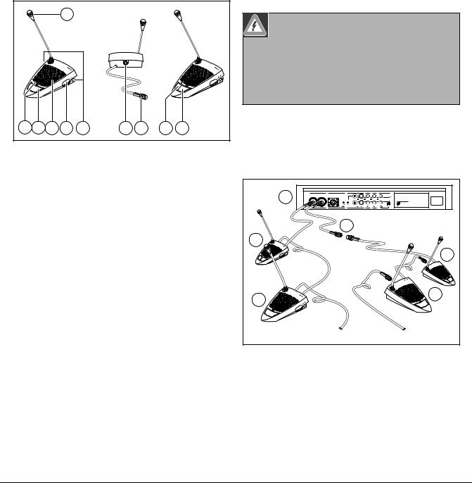
4Delegate and Chairman unit
5 Installation
1
A |
B |
4 |
8 |
3 |
7 |
2 |
5 |
6 |
9 |
8 |
Figure 4.1
The chairman unit (B) has the same function as a Delegate unit (A) with the exception of a 'priority' button.
1Microphone with red illuminated indicator ring, lights when the microphone is ON.
2Two 3.5 mm stereo headphone sockets, one at each side, for headphone or recorder connection. Insertion of a headphone jack in one or both sockets
automatically mutes the unit's loudspeaker.
3Built-in loudspeaker, automatically muted when the microphone is on.
4 Red (LED) indicator above the microphone push button, for microphone ON indication.
5 7-pole circular female socket for loopthrough connection to the next unit.
6 2m flying lead connection cable with sturdy moulded 7-pole circular male connector for connection to the previous unit or CPSU.
7 Rotary volume control for headphones only.
8 Microphone ON/OFF push-button.
Warning
The CPSU must be earthed via the mains supply for safety reasons and to ensure the specified audio performance of the system. Do not open the CPSU and/or delegate/chairman units, no user serviceable parts inside.
5.1Connecting the delegate and chairman units
Trunk in/out |
Microphone |
Recorder |
Line |
Telephone Insertion |
|
|
1 |
|
|
|
|
In |
|
|
|
|
|
Out |
Digital Acoustic |
|
|
Gain Gain |
|
|
Feedback Suppression |
||
|
|
|
|
|
|
90-260 V~ |
|
|
4 |
|
|
|
|
3 |
|
|
|
|
|
|
1 |
|
|
|
|
|
3 |
|
|
|
|
|
|
1 |
2 |
|
|
|
2 |
|
2 |
|
|
|
|
|
|
|
2 |
|
|
|
|
|
|
|
3...25 |
|
|
|
3...25 |
|
Figure 5.1
Connect the delegate (2) and chairman (3) units to the trunk connectors of the CPSU (1). Use an extension cable (4) if necessary.
Bosch Security Systems | 2003-06 | 3922 988 54284

CCS 800 Ultro | Installation and Operating Manual |
en | 8 |
|
|
5.2 Connecting up to 150 units
CCS 800 Ultro can be used with up to 150 units by adding maximum 2 additional control units acting as power supply units only. The system is controlled by the master LBB 3310. The cables necessary for these connections can be delivered by your local dealer.
|
|
|
max. 6 x 25 units |
CCS 800 |
ULTRO |
|
|
|
|
|
|
|
CCS 800 |
ULTRO |
|
|
|
CCS 800 |
ULTRO |
|
|
|
|
Figure 5.2 |
|
|
|
5.3 Locking the extension cable
Figure 5.3
Cable locking clamps can be used in combination with the extension cables to prevent accidental disconnection.
5.4Connecting an external microphone
Trunk in/out |
Microphone |
Recorder |
Line |
Telephone |
Insertion |
|
1 |
|
|
|
|
In |
|
Gain |
Gain |
|
|
Out |
Digital Acoustic |
|
|
|
Feedback Suppression |
||||
|
|
|
|
|
|
90-260 V~ |
|
3 |
|
|
|
|
|
|
2 |
|
|
|
|
|
Figure 5.4
Put the external microphone (2) connector in the microphone input of the CPSU (1).
Adjust the sensitivity by use of the gain control (3). Use only microphones with balanced output.
The microphone input provides a 12V phantom power supply.
Bosch Security Systems | 2003-06 | 3922 988 54284
CCS 800 Ultro | Installation and Operating Manual |
en | 9 |
|
|
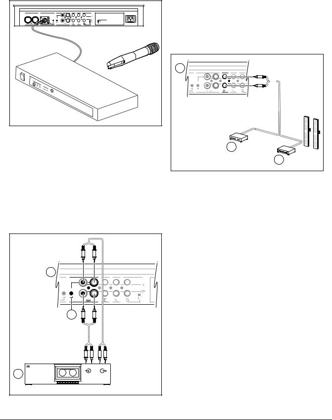
5.5Connecting a wireless microphone
Trunk in/out |
Microphone |
Recorder |
Line |
Telephone |
Insertion |
|
|
|
|
|
|
In |
|
|
Gain |
Gain |
|
|
Out |
Digital Acoustic |
|
|
|
|
Feedback Suppression |
||
|
|
|
|
|
|
90-260 V~ |
|
receiver |
|
|
|
|
|
Figure 5.5
Connecting a wireless microphone to the external microphone input is possible with the included 50dB attenuator. This way of connection allows interruption of the wireless microphone by the chairman's priority button.
5.6Recording/play back the conversation
1 |
|
|
|
Recorder |
Line |
Telephone |
Insertion |
|
|
|
In |
Gain Gain |
|
|
Out |
|
|
|
|
3 |
|
|
|
RECORD |
PLAY |
|
|
In |
Out |
|
|
2 |
|
|
|
Figure 5.6
Connect the cabling of the tape recorder (2) to the recorder input and output of the CPSU (1). Use the gain control (3) to adjust the sensitivity of the recorder input of the CPSU.
5.7Connecting a PA-system or other external equipment
1 |
Recorder |
Line |
Telephone |
Insertion |
|
|
|
|
In |
Gain |
Gain |
|
|
Out |
|
|
|
||
|
|
|
2 |
|
|
|
|
|
3 |
Figure 5.7
Connect a PA-system (3) or other devices (2) to the inand output of the CPSU (1).
Connect audio sources to the line input, a PA amplifier or other sound-processing devices to the line output.
Bosch Security Systems | 2003-06 | 3922 988 54284
 Loading...