


6 720 606 522 (01.10) AL
INSTALLATION AND OPERATING INSTRUCTIONS FOR AUTOMATIC INSTANTANEOUS TYPE WATER HEATERS FOR USE WITH NATURAL AND LIQUEFIED PETROLEUM GAS
MODEL 125B LPL and 125B NGL (Non-Modulated) Suitable for heating potable water
Certified for space heating in combination with potable water only
Not certified for space heating only. Intended for either recirculation to storage or cold water inlet flow that is non-varying. For variable flow, install the 125 B or the 125 X model.
WARNING
If the information in this manual is not followed exactly, a fire or explosion may result causing property damage, personal injury or death.
FOR YOUR SAFETY
Do not store or use gasoline or other flammable, combustible or corrosive vapors and liquids in the vicinity of this or any other appliance.
WHAT TO DO IF YOU SMELL GAS
- Do not try to light any appliance.
- Do not touch any electrical switch; do not use any phone in your building.
- Immediately call your gas supplier from a neighbor’s phone. Follow the gas supplier’s instructions.
- If you cannot reach your gas supplier, call the fire department.
- Installation and service must be performed by a qualified installer, service agency or the gas supplier.
TABLE OF CONTENTS
WARNING: Improper installation, adjustment, alteration, service or maintenance can cause injury or property damage. Refer to this manual. For assistance or additional information consult a qualified installer, service agency or the gas supplier. Upon completion of the installation, these instructions should be handed to the user of the appliance for future reference.
Warning: If you do not follow these instructions exactly, a fire or explosion may result causing property damage, personal injury or loss of life
Specifications .................................................... |
Page 2 |
Rules for safe operation ...................................... |
Page 4 |
Locating the Heater ............................................ |
Page 5 |
Combustion Air Requirements ............................ |
Page 5 |
Mounting the Heater ........................................... |
Page 6 |
Venting the Heater ............................................. |
Page 6 |
Gas Connections ............................................... |
Page 7 |
Water Connections ............................................ |
Page 8 |
Safety before lighting the pilot ............................ |
Page 9 |
Lighting instructions ........................................... |
Page 9 |
About Water Temperature .................................. |
Page 9 |
Maintenance & Service....................................... |
Page 9 |
Trouble Shooting .............................................. |
Page 10 |
Diagram of AquaStar......................................... |
Page 13 |
Components and Parts List .............................. |
Page 14 |
This well engineered, gas water heater has been specially designed to operate as a circulating water heater.
FEATURES
-High Quality Materials for Long Working Life.
-Copper heating coils for endless supply of hot water.
-Safety thermocouple at pilot burner.
-Automatic overheating protection shut-off sensor.
-Stainless steel burners with stabilized blue flame.
-Built-in corrosion resistant draft inducer.
-Compact space saver: mounts on a wall with two hooks.
-Easily removable one-piece cover.
-Easy one person installation.
-Easy pilot flame lighting with push button piezo ignition.
AquaStar 125B LPL and 125B NGL Specifications
Gas Input max.: 117,000 Btu/hr min.: 60,000 Btu/hr
Water Connection 1/2” Thread fitting
H x W x D 29 3/4” x 18 1/4” x 8 3/4"
Vent 5”
Gas Connection 1/2” NPT thread
Min. Water Pressure 8 Psi at 1.8 GPM
Min. Water Pressure 18 Psi at 3.7 GPM
Max. Water Pressure 150 Psi |
|
Shipping Weight 46 LB |
|
Net Weight 44 LB |
|
1.8 GPM at 90° rise |
|
3.7 GPM at 45° rise |
|
Min. Water Flow 1.8 gal/min |
|
LP GAS Supply Pressure |
|
(before Aquastar regulator) |
min.: 11” W.C. |
|
max.: 14” W.C.* |
Required LP GAS Pressure at inlet |
|
tap while Aquastar is operating: |
10.5” W.C. |
LP GAS Burner Manifold pressure while Aquastar is operating at maximum input: 9.0” W.C.
Natural Gas Supply Pressure |
|
(before Aquastar regulator) |
min.: 7” W.C. |
|
max.: 14” W.C.* |
Required Natural Gas Pressure at inlet |
|
tap while Aquastar is operating: |
5.7” W.C. |
Natural Gas Burner Manifold pressure while Aquastar is operating at maximum input: 4.2” W.C.
* Inlet gas pressure before Aquastar regulator must not exceed this value. Pressure may need to be adjusted for high altitudes, see page 8.
UNPACKING THE AQUASTAR HEATER
This heater is packed securely. The box includes two water connection fittings, a gas pressure regulator, a pressure relief valve, an incandescent particle tray, two hooks for hanging the heater, this manual, a warranty statement and a warranty registration card. Do not lose this manual, as there is a charge for replacement. Please complete and return the enclosed warranty registration card.
2

D861_059
FRONT VIEW |
SIDE VIEW |
MINIMUM INSTALLATION CLEARANCES FROM COMBUSTIBLE AND NON COMBUSTIBLE MATERIALS FOR ALCOVE OR CLOSET INSTALLATIONS
|
MODEL 125BL |
|
|
TOP (A) |
12" |
|
|
FRONT (B) |
4" |
|
|
BACK |
0" |
|
|
SIDES |
4" |
|
|
FLOOR (C) |
12" * |
|
|
FLUE DIAMETER |
5" |
|
|
* Some local codes require 18” in garage installations
AQUASTAR MODEL 125BL
3
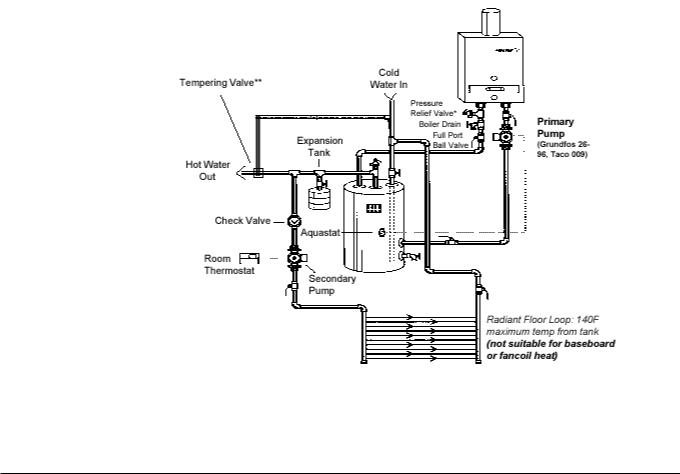
If you are using the AquaStar for combined space heating and potable water heating (see schematic diagram below), all piping and other components connected to the system must be suitable for potable water, (b) toxic chemicals such as those commonly used for boiler treatment to prevent corrosion and freezing must not be introduced into the system, and
(c) if the space heating requires water temperatures higher than those required for domestic, potable water, a mixing valve or other similar device must be provided to reduce scald hazard potential, (d) maximum system water temperature must not exceed 140°F (60°C). DO NOT CONVERT AN EXISTING, CLOSED HOT WATER HEATING SYSTEM TO A COMBINATION SPACE AND POTABLE WATER HEATING SYSTEM USING THE AQUASTAR OR ANY OTHER HEAT SOURCE.
Open loop potable water and combination space heating system*
* To be used with a tank, check local codes. May not be permitted in some jurisdictions.
Notes
1. Maximum to tank water temperature from 125 BL 140°F
2. Maximum heating capacity: |
40°F rise |
20°F rise |
AquaStar 125BL - |
80,000 BTU/hr |
40,000 BTU/hr |
3. System shown is electric storage tank with recirculating supply drawn from the tapping for the lower heating element.
4. If circulation flow to the Aquastar 125BL is restricted, it may be necessary to adjust the temperature slide control to prevent overheating.
5. Schematic is for illustration and example only and must not be used for actual installation without appropriate engineering and technical advice from a professional properly licensed in the locality where the installation is made.
*Pipe PRV to appropriate discharge
**Tempering valve is required when tank water temperature is over 130 F.
GENERAL RULES TO FOLLOW
FOR SAFE OPERATION
1.You should follow these instructions when you install your heater. In the United States: The installation must conform with local codes or, in the absence of local codes, the National Fuel Gas Code ANSI Z223.1/NFPA 54.
In Canada: The Installation should conform with CGA B149.(1,2) INSTALLATION CODES and/or local installation codes.
2.Carefully plan where you install the heater. Correct combustion air supply and flue pipe installation are very important. If not installed correctly, fatal accidents can be caused by lack of air, carbon monoxide poisoning or fire.
3.The place where you install the heater must have enough ventilation. The National Fire Codes do not allow gas fired water heater installation in bathrooms, bedrooms or any
occupied rooms normally kept closed. See the section below on locating the heater.
4.You must vent your heater. See section on VENTING, Page 6.
5.The appliance must be disconnected from the gas supply piping system during any pressure testing at pressures in excess of 1/2 Psig (3.5 kPa).
The appliance must be isolated from the gas supply piping system by closing its individual manual shutoff valve during any pressure testing of the gas supply piping system at test pressures equal to or less than 1/2 Psig (3.5kPa). The appliance and its gas connection must be leak tested before placing the appliance in operation.
6.Keep water heater area clear and free from combustibles and flammable liquids. Do not locate the heater over any material which might burn.
4
7.Correct gas pressure is critical for the optimum operation of this heater (see specifications on page 2). Gas piping must be sized to provide the required pressure at the maximum output of the heater, while all the other gas appliances are in operation. Check with your local gas supplier, and see the section on connecting the gas supply.
8.Should overheating occur or the gas supply fail to shut off, turn off the gas supply at the manual gas shut off valve on the gas line.
9.Do not use this appliance if any part has been underwater. Immediately call a qualified service technician to inspect the appliance and to replace any part of the control system and any gas control which has been underwater.
 WARNING: The water in this water heater is cold and always remains cold except for the times that hot water is being used DO NOT INSTALL IN AN AREA
WHERE IT COULD FREEZE.
This heater is neither designed for nor approved for outside installation.
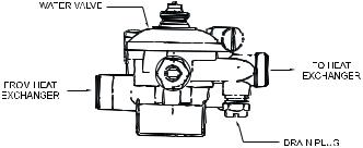
Drain the heater entirely if freezing temperatures are anticipated in area where heater is installed by disconnecting both the inlet and outlet elbow connections at the rear of heater. Additionally remove the drain plug under the water valve. See Fig 0.
PROPER LOCATION FOR INSTALLING YOUR HEATER
Carefully select the location of your new heater. For your safety and for proper heater operation, you must provide an abundant supply of combustion air and a proper venting installation.
The heater may still operate even when improperly vented. It will, however, be less efficient and could eventually damage the heater. It could even result in human sickness or death due to oxygen deprivation and carbon monoxide poisoning. Follow the guidelines below:
1.Place your heater as close to a vent or chimney as possible.
2.National building codes require that you do not install this appliance in bathrooms, bedrooms, unvented closet or any occupied rooms normally kept closed.
3.Simultaneous operation of other appliances such as exhaust fans, ventilation systems clothes dryers, fireplaces or wood stoves could create a vacuum effect in your home which could cause dangerous combustion by-products to spill back into your home rather than venting to the outside through the flue. Confirm that your Aquastar is venting properly when all these other appliances are running. See section on venting.
Do not obstruct the flow of combustion and ventilation air to the appliance. If installed near a clothes dryer it is very important that the dryer be properly vented. Failure to properly vent a dryer could result in a gradual accumulation of lint on the water heater fin coils and burners, leading to a dangerous condition of vent blockage and poor unsafe combustion.
4. Your hot water lines should be kept short to save energy. It is always best to have hot water lines insulated.
This product is not approved for manufactured homes (mobile home), recreational vehicles (RV) or boats. Reference ANSI Z21.10.3.
This product is neither designed or approved for outside installations.
Fig. 0 - Water heater drain plug
 WARNING: Flammable materials, gasoline, pressurized containers, or any other items or articles that are potentially fire hazards must NOT be placed on or adjacent to the heater. The appliance area must be kept free of all combustible materials, gasoline and other flammable vapors and liquids.
COMBUSTION AIR REQUIREMENTS
The AquaStar water heater holds cold water in its copper heat exchanger and brass water valve when not in use. Because of this, any cold air that comes in through the unit’s vent pipe is capable of freezing these components. This Installation Manual specifies the minimum vertical vent pipe and the amount of combustion air required for this unit. The vent pipe must not be restricted and its 6 foot minimum height (provided there are no elbows) must terminate 2 feet above any obstruction within a 10 foot radius.
When all requirements are followed, the unit will operate properly and safely. However, there may still be a risk of freezing due to negative draft if all the combustion appliances in the area are not being supplied with a sufficient amount of make-up air. A wood stove or furnace can rob the makeup air in theAquaStar’s vent pipe, leaving the cold infiltrating air capable of freezing the cold water in the AquaStar heat exchanger. More make up air is the solution. Follow the instructions on venting and checking adequacy of make up air. A HVAC specialist should be used to design solutions for providing more make-up air if necessary.
Observe the following instructions concerning combustion air.
Appliances located in unconfined spaces:
a)An unconfined space is one whose volume is greater than 50 cubic feet per 1000 Btu per hour of the combined rating of all appliances installed in the space. That would be 5850 cubic feet for the AquaStar 125BL alone.
b)In unconfined spaces in buildings of conventional frame, masonry, or metal construction, infiltration is normally adequate to provide air for combustion, ventilation, and
5
 Loading...