


LTC 8500 Series
Instruction Manual
EN Allegiant Microprocessor-
based Video Switcher/
Control Systems
BOSCH
EN | ii |
Bosch Security Systems | December 13, 2005 |
Product | Instruction Manual | Important Safeguards
Important Safeguards
1.Read, Follow, and Retain Instructions - All safety and operating instructions should be read and followed before operating the unit. Retain instructions for future reference.
2.Heed Warnings - Adhere to all warnings on the unit and in the operating instructions.
3.Attachments - Attachments not recommended by the product manufacturer should not be used, as they may cause hazards.
4.Installation Cautions - Do not place this unit on an unstable stand, tripod, bracket, or mount. The unit may fall, causing serious injury to a person and serious damage to the unit. Use only manufacturerrecommended accessories, or those sold with the product. Mount the unit per the manufacturer's instructions. Appliance and cart combination should be moved with care. Quick stops, excessive force, or uneven surfaces may cause the appliance and cart combination to overturn.
5.Cleaning - Unplug the unit from the outlet before cleaning. Follow any instructions provided with the unit. Generally, using a damp cloth for cleaning is sufficient. Do not use liquid cleaners or aerosol cleaners.
6.Servicing - Do not attempt to service this unit yourself. Opening or removing covers may expose you to dangerous voltage or other hazards. Refer all servicing to qualified service personnel.
7.Damage Requiring Service - Unplug the unit from the main AC power source and refer servicing to qualified service personnel under the following conditions:
•When the power supply cord or plug is damaged.
•If liquid has been spilled or an object has fallen into the unit.
•If the unit has been exposed to water and/or inclement weather (rain, snow, etc.).
•If the unit does not operate normally, when following the operating instructions. Adjust only those controls specified in the operating instructions. Improper adjustment of other controls may result in damage, and require extensive work by a qualified technician to restore the unit to normal operation.
•If the unit has been dropped or the cabinet damaged.
•If the unit exhibits a distinct change in performance, this indicates that service is needed.
8.Replacement Parts - When replacement parts are required, the service technician should use replacement parts specified by the manufacturer or that have the same characteristics as the original part. Unauthorized substitutions may result in fire, electrical shock or other hazards.
9.Safety Check - Upon completion of servicing or repairs to the unit, ask the service technician to perform safety checks to ensure proper operating condition.
10.Power Sources - Operate the unit only from the type of power source indicated on the label. If unsure of the type of power supply to use, contact your dealer or local power company.
•For units intended to operate from battery power, refer to the operating instructions.
•For units intended to operate with External Power Supplies, use only the recommended approved power supplies.
•For units intended to operate with a limited power source, this power source must comply with EN60950. Substitutions may damage the unit or cause fire or shock.
•For units intended to operate at 24VAC, normal input voltage is 24VAC. Voltage applied to the unit's power input should not exceed 30VAC. User-supplied wiring, from the 24VAC supply to unit, must be in compliance with electrical codes (Class 2 power levels). Do not ground the 24VAC supply at the terminals or at the unit's power supply terminals.
11.Coax Grounding - If an outside cable system is connected to the unit, ensure that the cable system is grounded. U.S.A. models only - Section 810 of the National Electrical Code, ANSI/NFPA No.70, provides information regarding proper grounding of the mount and supporting structure, grounding of the coax to a discharge unit, size of grounding conductors, location of discharge unit, connection to grounding electrodes, and requirements for the grounding electrode.
12.Grounding - This unit may be equipped with a 3- wire grounding plug (a plug with a third pin, for grounding). This safety feature allows the plug to fit into a grounding power outlet only. If unable to insert the plug into the outlet, contact an electrician to arrange replacement of the obsolete outlet. Do not defeat the safety purpose of the grounding plug.
•Outdoor equipment should only be connected to the unit's inputs after this unit has had its grounding plug connected to a grounded outlet or its ground terminal properly connected to a ground source.
•The unit's input connectors must be disconnected from outdoor equipment before disconnecting the grounding plug or grounding terminal.
•Proper safety precautions such as grounding should be followed for any outdoor device connected to this unit.
13.Lightning - For added protection during a lightning storm, or when this unit is left unattended and unused for long periods of time, unplug the unit from the wall outlet and disconnect the cable system. This will prevent damage to the unit due to lightning and power line surges.
EN | iii
Product | Instruction Manual | Safety Precautions
For Indoor Product
1.Water and Moisture - Do not use this unit near water - for example, in a wet basement, in an unprotected outdoor installation or in any area classified as a wet location.
2.Object and Liquid Entry - Never push objects of any kind into this unit through openings, as they might touch dangerous voltage points or create short circuits, resulting in a fire or electrical shock. Never spill liquid of any kind on the unit.
3.Power Cord and Power Cord Protection - For units intended to operate with 230VAC, 50Hz, the input and output power cord must comply with the latest versions of IEC Publication 227 or IEC Publication 245.
Power supply cords should be routed so they are not likely to be walked on or pinched. Pay particular attention to location of cords and plugs, convenience receptacles, and the point of exit from the appliance.
4.Overloading - Do not overload outlets and extension cords; this can result in a risk of fire or electrical shock.
For Outdoor Product
Power Lines - An outdoor system should not be located in the vicinity of overhead power lines, electric lights or power circuits, or where it may contact such power lines or circuits. When installing an outdoor system, extreme care should be taken to keep from touching power lines or circuits, as this contact might be fatal. U.S.A. models only - refer to the National Electrical Code Article 820 regarding installation of CATV systems.
For Rack-mount Product
1.Ventilation - Do not place this equipment in a built-in installation or rack, unless proper ventilation is provided, or the manufacturer's instructions were followed. The equipment must not exceed its maximum operating temperature requirements.
2.Mechanical Loading - When rack-mounting the equipment, ensure that a hazardous condition is not created by uneven mechanical loading.
Safety Precautions
CAUTION: TO REDUCE THE RISK OF ELECTRIC SHOCK, DO NOT REMOVE COVER (OR BACK). NO USER SERVICEABLE PARTS INSIDE. REFER SERVICING TO QUALIFIED SERVICE PERSONNEL.
This symbol indicates the presence of uninsulated “dangerous voltage” within the product’s enclosure that can cause an electric shock.
This symbol indicates the presence of important operating and maintenance (servicing) instructions in the literature accompanying the appliance.
Installation should be performed by qualified service personnel only in accordance with the National Electrical Code or applicable local codes.
Power Disconnect. Units with or without ON-OFF switches have power supplied to the unit whenever the power cord is inserted into the power source; however, the unit is operational only when the ON-OFF switch is in the ON position. The power cord is the main power disconnect for all units.
EN | iv |
Bosch Security Systems | December 13, 2005 |
Product | Instruction Manual | FCC & ICES Information
FCC & ICES INFORMATION
(U.S.A. and Canadian Models Only)
This device complies with part 15 of the FCC Rules. Operation is subject to the following two conditions:
(1)This device may not cause harmful interference, and
(2)This device must accept any interference received, including interference that may cause undesired operation.
NOTE: This equipment has been tested and found to comply with the limits for a Class B digital device, pursuant to Part 15 of the FCC Rules and ICES-003 of Industry Canada. These limits are designed to provide reasonable protection against harmful interference when the equipment is operated in a residential installation. This equipment generates, uses and can radiate radio frequency energy, and if not installed and used in accordance with the instructions, may cause harmful interference to radio communications. However, there is no guarantee that interference will not occur in a particular installation. If this equipment does cause harmful interference to radio or television reception, which can be determined by turning the equipment off and on, the user is encouraged to try to correct the interference by one or
more of the following measures:
•Reorient or relocate the receiving antenna.
•Increase the separation between the equipment and receiver.
•Connect the equipment into an outlet on a circuit different from that to which the receiver is connected.
•Consult the dealer, or an experienced radio/TV technician for help.
Intentional or unintentional changes or modifications, not expressly approved by the party responsible for compliance, shall not be made. Any such changes or modifications could void the user’s authority to operate the equipment.The user may find the following booklet, prepared by the Federal Communications Commission, helpful: How to Identify and Resolve Radio-TV Interference Problems. This booklet is available from the U.S. Government Printing Office, Washington, DC 20402,
Stock No. 004-000-00345-4.
Sécurité
ATTENTION : POUR ÉVITER TOUT RISQUE D'ÉLECTROCUTION,
N'ESSAYEZ PAS DE RETIRER LE CAPOT (OU LE PANNEAU
ARRIÈRE). CET APPAREIL NE CONTIENT AUCUN COMPOSANT
SUSCEPTIBLE D'ÊTRE RÉPARÉ PAR L'UTILISATEUR. CONFIEZ
LA RÉPARATION DE L'APPAREIL À DU PERSONNEL QUALIFIÉ.
Ce symbole signale que le produit renferme une « tension potentiellement dangereuse » non isolée susceptible de provoquer une électrocution.
Ce symbole invite l'utilisateur à consulter les instructions d'utilisation et d'entretien (dépannage) reprises dans la documentation qui accompagne l'appareil.
Attention : l'installation doit exclusivement être réalisée par du personnel qualifié, conformément au code national d'électricité américain (NEC) ou au code d'électricité local en vigueur.
Coupure de l'alimentation. Qu'ils soient pourvus ou non d'un commutateur ON/OFF, tous les appareils reçoivent de l'énergie une fois le cordon branché sur la source d'alimentation. Toutefois, l'appareil ne fonctionne réellement que lorsque
le commutateur est réglé sur ON. Le débranchement du cordon d'alimentation permet de couper l'alimentation des appareils.
Sicherheitshinweise
VORSICHT: UM EINEN ELEKTRISCHEN SCHLAG ZU
VERMEIDEN, IST DIE ABDECKUNG (ODER RÜCKSEITE) NICHT
ZU ENTFERNEN. ES BEFINDEN SICH KEINE TEILE IN DIESEM
BEREICH, DIE VOM BENUTZER GEWARTET WERDEN
KÖNNEN. LASSEN SIE WARTUNGSARBEITEN NUR VON
QUALIFIZIERTEM WARTUNGSPERSONAL AUSFÜHREN.
Das Symbol macht auf nicht isolierte „gefährliche Spannung" im Gehäuse aufmerksam. Dies kann zu einem elektrischen Schlag führen.
Der Benutzer sollte sich ausführlich über Anweisungen für die Bedienung und Instandhaltung (Wartung) in den begleitenden Unterlagen informieren.
Achtung! Die Installation sollte nur von qualifiziertem
Kundendienstpersonal gemäß jeweils zutreffender
Elektrovorschriften ausgeführt werden.
Unterbrechung des Netzanschlusses. Geräte mit oder ohne Netzschalter haben Spannung am Gerät anliegen, sobald der Netzstecker in die Steckdose gesteckt wird. Das Gerät ist jedoch nur betriebsbereit, wenn der Netzschalter (EIN/AUS) auf EIN steht. Wenn das Netzkabel aus der Steckdose gezogen wird, ist die Spannungszuführung zum Gerät vollkommen unterbrochen.
Precauciones de Seguridad
PRECAUCIÓN: PARA DISMINUIR EL RIESGO DE DESCARGA ELÉCTRICA, NO RETIRE LA CUBIERTA (NI LA PARTE POSTERIOR). NO EXISTEN PIEZAS DE RECAMBIO EN EL INTERIOR DEL EQUIPO. EL PERSONAL DE SERVICIO CUALIFICADO SE ENCARGA DE REALIZAR LAS REPARACIONES.
Este símbolo indica que existen puntos de tensión peligrosos sin aislamiento dentro de la cubierta de la unidad. Estos puntos pueden constituir un riesgo de descarga eléctrica.
El usuario debe consultar las instrucciones de funcionamiento y mantenimiento (reparación) en la documentación que se suministra con el aparato.
Atención: la instalación la debe realizar únicamente personal cualificado de conformidad con el National Electric Code o las normas aplicables en su país.
Desconexión de la alimentación. Las unidades con o sin interruptores de encendido/apagado reciben alimentación eléctrica siempre que el cable de alimentación esté conectado a la fuente de alimentación. Sin embargo, la unidad sólo funciona cuando el interruptor está en la posición de encendido. El cable de alimentación es la principal fuente de desconexión de todas las unidades.
EN | v

Product | Instruction Manual | Safety Precautions
Veiligheidsmaatregelen |
|
Medidas de Segurança |
||||||||||||||||||||
|
|
|
|
|
|
|
|
|
|
|
|
|
|
|
|
|
|
|
|
|
|
|
|
|
|
|
|
|
|
|
|
|
|
|
|
|
|
|
|
|
|
|
|
|
|
|
|
|
|
|
|
|
|
|
|
|
|
|
|
|
|
|
|
|
|
|
|
|
|
|
|
|
|
|
|
|
|
|
|
|
|
|
|
|
|
|
|
|
|
|
|
|
|
|
|
|
|
|
|
|
|
|
|
|
|
|
|
|
|
|
|
|
|
|
|
|
|
|
|
|
|
|
|
|
|
|
|
|
|
|
|
|
|
|
|
|
|
|
|
|
|
|
|
|
|
|
|
|
|
|
|
|
|
|
|
|
|
|
|
|
|
|
|
|
|
|
|
|
|
|
|
|
|
|
|
|
|
|
|
|
|
|
|
VOORZICHTIG: OPEN DE BEHUIZING OF DE ACHTERKANT VAN HET APPARAAT NIET. ZO VERMINDERT U HET RISICO OP ELEKTRISCHE SCHOKKEN. IN HET APPARAAT BEVINDEN ZICH GEEN ONDERDELEN DIE U ZELF KUNT REPAREREN. LAAT SERVICE EN ONDERHOUD UITVOEREN DOOR GEKWALIFICEERD PERSONEEL.
Dit symbool geeft aan dat er binnen in het apparaat ongeïsoleerde, gevaarlijke spanning aanwezig is die mogelijk elektrische schokken kan veroorzaken.
De gebruiker dient de bedieningsen onderhoudsvoorschriften te raadplegen in de documentatie die werd meegeleverd met het apparaat.
Attentie: het apparaat mag alleen door gekwalificeerd personeel worden geïnstalleerd. De installatie dient in overeenstemming met de nationale elektrische richtlijnen of de van toepassing zijnde lokale richtlijnen te worden uitgevoerd.
Spanning uitschakelen. Apparatuur met of zonder aan-uitschakelaar staat onder spanning zolang de stekker is aangesloten op de wandcontactdoos. De apparatuur is uitsluitend in werking als de aan-uitschakelaar aan staat. Het netsnoer is de "hoofdschakelaar" voor alle apparatuur.
CUIDADO: PARA REDUZIR O RISCO DE CHOQUE
ELÉCTRICO, NÃO RETIRE A TAMPA (OU A PARTE
POSTERIOR). NO INTERIOR, NÃO EXISTEM PEÇAS QUE
POSSAM SER REPARADAS PELO UTILIZADOR. REMETA A
ASSISTÊNCIA PARA OS TÉCNICOS QUALIFICADOS.
Este símbolo indica a presença de "tensão perigosa" não isolada dentro da estrutura do produto, o que pode constituir risco de choque eléctrico.
O utilizador deve consultar as instruções de funcionamento e manutenção (assistência) nos documentos que acompanham o aparelho.
Atenção: a instalação deve ser executada apenas por técnicos qualificados da assistência, de acordo com o código eléctrico nacional ou os códigos locais aplicáveis.
Corte de corrente. As unidades com ou sem interruptores ON-OFF (ligar/desligar) recebem corrente sempre que o fio de alimentação está introduzido na fonte de alimentação; contudo, a unidade apenas está operacional quando o interruptor ON-OFF está na posição ON. O fio de alimentação destina-se a desligar a corrente em todas as unidades.
Sicurezza
ATTENZIONE: PER RIDURRE IL RISCHIO DI SCOSSE ELETTRICHE NON RIMUOVERE LA COPERTURA (O IL PANNELLO POSTERIORE). L'UNITÀ NON CONTIENE COMPONENTI INTERNI RIPARABILI DALL'UTENTE. PER QUALSIASI INTERVENTO, RIVOLGERSI A PERSONALE TECNICO QUALIFICATO.
Questo simbolo indica la presenza di "tensione pericolosa" non isolata all'interno del contenitore del prodotto. Ciò comporta un potenziale rischio di scosse elettriche.
Si consiglia di consultare le istruzioni operative e di manutenzione (interventi tecnici) contenute nella documentazione fornita con il dispositivo.
Attenzione: l'installazione deve essere effettuata esclusivamente da personale tecnico qualificato in conformità con il National Electrical Code o con le normative locali vigenti.
Scollegamento dell'alimentazione. Le unità dotate o sprovviste di interruttori ON-OFF vengono alimentate quando si inserisce il cavo nella presa dell'alimentazione. L'unità è tuttavia in funzione solo quando l'interruttore ON-OFF si trova nella posizione ON. Il cavo di alimentazione costituisce il dispositivo di scollegamento dell'alimentazione principale per tutte le unità.
EN | vi |
Bosch Security Systems | December 13, 2005 |
1. |
Unpacking ........................................................................................................................................................... |
1 |
|
|
1.1 |
Parts List ................................................................................................................................................. |
1 |
2. |
Service.................................................................................................................................................................. |
2 |
|
3. |
Description.......................................................................................................................................................... |
3 |
|
4. Allegiant Feature Summary Table ................................................................................................................ |
5 |
||
5. |
System Components ......................................................................................................................................... |
7 |
|
|
5.1 |
LTC 8501 Series Systems ....................................................................................................................... |
7 |
6. |
System Accessory Components...................................................................................................................... |
8 |
|
|
6.1 |
LTC 8540/00 Alarm Interface Unit ...................................................................................................... |
8 |
|
6.2 |
LTC 8568 and LTC 8768 Signal Distribution Units ........................................................................... |
8 |
|
6.3 |
IntuiKey Series KBD-Universal Keyboard........................................................................................... |
8 |
|
6.4 |
KBD-Rack Keyboard Mounting Kit...................................................................................................... |
8 |
|
6.5 |
LTC 8555 Series Keyboards .................................................................................................................. |
9 |
|
6.6 |
LTC 8558/00 Keyboard Extension Cable............................................................................................ |
9 |
|
6.7 |
LTC 8557 Series Keyboard Extension Kits.......................................................................................... |
9 |
|
6.8 |
LTC 8560 and LTC 8561 Series Receiver/Driver Units .................................................................... |
9 |
|
6.9 |
AutoDome Series..................................................................................................................................... |
9 |
|
6.10 |
LTC 8569, LTC 8570, LTC 8571, LTC 8572 Series Code Merger Units ..................................... |
10 |
|
6.11 |
LTC 8770 Switcher Follower Series ................................................................................................... |
10 |
|
6.12 |
LTC 8712 Series Console Port Expander Units ............................................................................... |
10 |
|
6.13 |
LTC 8713 Alarm Port Expander Units.............................................................................................. |
10 |
|
6.14 |
LTC 8780 Series Data Converter Units............................................................................................. |
11 |
|
6.15 |
LTC 8781 Series Data Converter Units............................................................................................. |
11 |
|
6.16 |
LTC 8016/90 Bilinx™ Data Interface Unit........................................................................................ |
11 |
|
6.17 |
LTC 8785 Series Code Converters .................................................................................................... |
11 |
|
6.18 |
LTC 8782 Series Code Translator Units ........................................................................................... |
11 |
|
6.19 |
LTC 8059/00 Master Control Software ............................................................................................. |
12 |
|
6.20 |
LTC 8850/00 Windows Based Graphical User Interface Software ................................................ |
12 |
|
6.21 |
SFT-INTSRV Allegiant Integration Software ................................................................................... |
12 |
|
|
6.21.1 Integration Server......................................................................................................................... |
12 |
|
|
6.21.2 Virtual Allegiant Satellite Application Software ....................................................................... |
12 |
|
|
6.21.3 Allegiant Satellite Software Development Kit........................................................................... |
13 |
|
6.22 |
LTC 8506/00 PC-to-Console Port RS-232 Cable ............................................................................. |
13 |
|
6.23 |
Logging Printer ..................................................................................................................................... |
14 |
7. |
Installation Procedure .................................................................................................................................... |
16 |
|
|
7.1 |
Main CPU Bay Installation ................................................................................................................. |
16 |
|
7.2 |
Video Input Modules ........................................................................................................................... |
16 |
|
7.3 |
Video Output Modules ........................................................................................................................ |
17 |
|
7.4 |
CPU Module ......................................................................................................................................... |
17 |
|
7.5 |
Camera and Monitor Video Connections ......................................................................................... |
18 |
|
7.6 |
Termination Practices .......................................................................................................................... |
18 |
|
|
7.6.1 LTC 8500 Series Video Terminations ....................................................................................... |
18 |
|
|
7.6.2 Monitor Output Video Connections.......................................................................................... |
18 |
8. |
Optional Accessories Installation ................................................................................................................ |
19 |
|
|
8.1 |
General Accessory Installation............................................................................................................ |
19 |
|
8.2 |
Logging Printer Option Installation ................................................................................................... |
19 |
|
8.3 |
Computer Interface Installation .......................................................................................................... |
20 |
EN | vii
9. |
Satellite Configuration Installations ........................................................................................................... |
21 |
||
|
9.1 |
Satellite Site “Trunk Line” Monitor Outputs .................................................................................... |
21 |
|
|
9.2 |
Main Site “Trunk Line” Video Inputs ............................................................................................... |
22 |
|
|
9.3 |
Control Data Lines in Satellite Systems ............................................................................................. |
22 |
|
|
9.4 |
Satellite Site Programming Requirements ......................................................................................... |
22 |
|
|
9.5 |
Main Site Programming Requirements.............................................................................................. |
23 |
|
|
9.6 |
Special Programming for “Cascaded” Satellite System Configurations ......................................... |
25 |
|
|
9.7 |
Alarm Inputs in Satellite Systems ....................................................................................................... |
26 |
|
10. |
Feature Selection ............................................................................................................................................. |
27 |
||
11. |
Main Power Connections............................................................................................................................... |
28 |
||
12. |
Video Monitor Display .................................................................................................................................. |
29 |
||
|
12.1 |
Time / Date........................................................................................................................................... |
29 |
|
|
12.2 |
Monitor Title/System Status Display ................................................................................................. |
29 |
|
|
|
12.2.1 |
Monitor Message .......................................................................................................................... |
29 |
|
|
12.2.2 |
System Status Display .................................................................................................................. |
30 |
13. |
Factory Default Settings ................................................................................................................................. |
33 |
||
|
13.1 |
User Selectable DIP Switch Settings for Main CPU Bay................................................................. |
33 |
|
|
|
13.1.1 Upper CPU DIP Switch S1001................................................................................................... |
33 |
|
|
|
13.1.2 Lower CPU DIP Switch S1002................................................................................................... |
34 |
|
14. |
User Information ............................................................................................................................................. |
38 |
||
|
14.1 |
User Priority Levels.............................................................................................................................. |
38 |
|
|
14.2 |
User Priority Access Table .................................................................................................................. |
39 |
|
15. |
Alarm Information .......................................................................................................................................... |
40 |
||
|
15.1 |
General .................................................................................................................................................. |
40 |
|
|
15.2 |
Basic Alarm Response Mode .............................................................................................................. |
40 |
|
|
15.3 |
Auto Build Alarm Response Mode .................................................................................................... |
40 |
|
|
15.4 |
Sequence and Display Alarm Response Mode ................................................................................. |
40 |
|
|
15.5 |
Alarm Activated Pre-position.............................................................................................................. |
41 |
|
|
15.6 |
Sample Alarm Responses .................................................................................................................... |
41 |
|
|
15.7 |
Alarm Relay Response ........................................................................................................................ |
43 |
|
16. |
Keyboard Operation ...................................................................................................................................... |
44 |
||
|
16.1 |
General .................................................................................................................................................. |
44 |
|
|
16.2 |
System Commands............................................................................................................................... |
44 |
|
|
|
16.2.1 |
Keyboard Log-in Procedure........................................................................................................ |
44 |
|
|
16.2.2 |
Keyboard Log-off Procedure....................................................................................................... |
45 |
|
16.3 |
Switcher Commands ............................................................................................................................ |
45 |
|
|
16.4 |
Controlling Camera Movement.......................................................................................................... |
45 |
|
|
|
16.4.1 |
General .......................................................................................................................................... |
45 |
|
|
16.4.2 Focus and Iris Lens Control........................................................................................................ |
45 |
|
|
|
16.4.3 Lock or Unlock Control of a Camera........................................................................................ |
45 |
|
|
|
16.4.4 Lock or Unlock Control of a Monitor ....................................................................................... |
46 |
|
|
|
16.4.5 Recording a Camera Pre-position Scene ................................................................................... |
46 |
|
|
|
16.4.6 Recalling a Camera Pre-position Scene..................................................................................... |
46 |
|
|
|
16.4.7 |
Activate/Deactivate Auxiliary Function .................................................................................... |
46 |
|
16.5 |
Alarm Commands ................................................................................................................................ |
47 |
|
|
|
16.5.1 |
Arm/Disarm Individual Alarms ................................................................................................. |
47 |
|
|
16.5.2 |
Arm/Disarm All Alarms.............................................................................................................. |
48 |
EN | viii |
Bosch Security Systems | December 13, 2005 |
|
16.5.3 |
Arm/Disarm Monitor .................................................................................................................. |
48 |
|
16.5.4 |
Alarms Acknowledgement .......................................................................................................... |
48 |
16.6 |
Sequence Control ................................................................................................................................. |
48 |
|
|
16.6.1 |
Load/Clear a Sequence ............................................................................................................... |
48 |
|
16.6.2 |
Run a Sequence ............................................................................................................................ |
49 |
|
16.6.3 |
Stop a Running Sequence ........................................................................................................... |
49 |
|
16.6.4 |
Controlling Sequence Direction ................................................................................................. |
49 |
16.7 |
Sequence Programming ....................................................................................................................... |
50 |
|
|
16.7.1 |
Programming a Simple Camera Sequence................................................................................ |
50 |
|
16.7.2 |
Programming a SalvoSwitching Camera Sequence.................................................................. |
52 |
17. Keyboard User Functions .............................................................................................................................. |
53 |
||
17.1 |
General Information............................................................................................................................. |
53 |
|
|
17.1.1 |
User Function 1 - Local Keyboard Test..................................................................................... |
55 |
|
17.1.2 |
User Function 2 - Show Keyboard Port Number ..................................................................... |
56 |
|
17.1.3 |
User Function 3 - Select Keyboard Beeper ON/OFF.............................................................. |
56 |
|
17.1.4 |
User Function 4 - Adjust Position of Monitor Overlay............................................................ |
56 |
|
17.1.5 |
User Function 5 - Monitor Display Brightness / Status Selection........................................... |
56 |
|
17.1.6 |
User Function 6 - Select Monitor Display Option.................................................................... |
56 |
|
17.1.7 |
User Function 7 - Set Time ......................................................................................................... |
57 |
|
17.1.8 |
User Function 8 - Set Date .......................................................................................................... |
57 |
|
17.1.9 |
User Function 9 - Set Camera ID............................................................................................... |
57 |
|
17.1.10 |
User Function 10 - Change USER Password ............................................................................ |
57 |
|
17.1.11 |
User Function 11 - Select Time / Date Format......................................................................... |
58 |
|
17.1.12 |
User Function 12 - Default All Monitor Overlays.................................................................... |
58 |
|
17.1.13 |
User Function 13 - Print System Configuration Tables ........................................................... |
58 |
|
17.1.14 |
User Function 14 - Reserved Function ...................................................................................... |
58 |
|
17.1.15 |
User Function 15 - System Reset................................................................................................ |
58 |
|
17.1.16 |
User Function 16 - Time Event Enable/Disable....................................................................... |
58 |
|
17.1.17 |
User Function 17 - Set Monitor ID ............................................................................................ |
58 |
|
17.1.18 |
User Function 18 - Print Sequence............................................................................................. |
59 |
|
17.1.19 |
User Function 19 - Select Alarm Response............................................................................... |
59 |
|
17.1.20 |
User Function 20 - Select Printer Verbosity.............................................................................. |
59 |
|
17.1.21 |
User Function 21 - Designate Alarm Monitor Type ................................................................ |
59 |
|
17.1.22 |
User Function 22 - Select Control Code Format ...................................................................... |
59 |
|
17.1.23 |
User Function 23 - Display CPU Software Version Number ................................................. |
60 |
|
17.1.24 |
User Function 24 - Set Positions on All Monitor Displays ...................................................... |
60 |
|
17.1.25 |
User Function 25 - Set Brightness on All Monitor Displays ................................................... |
60 |
|
17.1.26 |
User Function 26 - Set Display Option On All Monitors........................................................ |
60 |
|
17.1.27 |
User Function 27 - Select Keyboard Log-in .............................................................................. |
60 |
|
17.1.28 |
User Function 28 - Select Console Log-in ................................................................................. |
61 |
|
17.1.29 |
User Function 29 - Reset RS-232 Parameters to Default ......................................................... |
61 |
|
17.1.30 |
User Function 30 - Set Console RS-232 Parameters ................................................................ |
61 |
|
17.1.31 |
User Function 31 - Set Printer RS-232 Parameters................................................................... |
61 |
|
17.1.32 |
User Function 32 - Set Alarm RS-232 Parameters ................................................................... |
61 |
|
17.1.33 |
User Function 33 - Display User Number and Priority ........................................................... |
61 |
|
17.1.34 |
User Function 34 - Camera Indicator ........................................................................................ |
62 |
|
17.1.35 |
User Function 35 - Controllable Cameras................................................................................. |
62 |
|
17.1.36 |
User Function 36 - Select Crosspoint Data ............................................................................... |
62 |
|
17.1.37 |
User Function 37 - R/D Address Mode .................................................................................... |
62 |
|
17.1.38 |
User Function 38 - Printer Port Mode ....................................................................................... |
62 |
|
17.1.39 |
User Function 39 - Select DIU Interface Port........................................................................... |
62 |
|
17.1.40 |
User Function 40 - Reserved Function ...................................................................................... |
62 |
|
17.1.41 |
User Function 41 - Set Satellite Communication Format ........................................................ |
62 |
EN | ix
|
|
17.1.42 User Function 42 - Keyboard Log-in Auto-off Mode............................................................... |
64 |
|
|
|
17.1.43 User Function 43 - CPU Battery Status ..................................................................................... |
64 |
|
|
|
17.1.44 User Function 99 - User Function Index ................................................................................... |
64 |
|
18. |
Maintenance Information.............................................................................................................................. |
65 |
||
|
18.1 |
Cleaning the Keyboard........................................................................................................................ |
65 |
|
|
18.2 |
AC Line Voltage Input Selection ....................................................................................................... |
65 |
|
|
18.3 |
AC Line Fuse Replacement ................................................................................................................ |
66 |
|
|
18.4 |
Power Supply Fuse Replacement ....................................................................................................... |
66 |
|
|
18.5 |
Replacement of Memory Backup Batteries ....................................................................................... |
66 |
|
19. |
Character ROM Tables for LTC 8500......................................................................................................... |
68 |
||
20. |
Error Messages ................................................................................................................................................. |
70 |
||
21. |
Troubleshooting Guide .................................................................................................................................. |
73 |
||
|
21.1 |
Main Bay Checkout ............................................................................................................................. |
73 |
|
|
21.2 |
Keyboard Checkout ............................................................................................................................. |
73 |
|
|
21.3 |
Video Monitor Display Checkout ...................................................................................................... |
74 |
|
|
21.4 |
Remote Receiver/Driver Functions Inoperative............................................................................... |
74 |
|
|
21.5 |
No Alarm Response ............................................................................................................................. |
74 |
|
|
21.6 |
CPU Software Version Numbers........................................................................................................ |
75 |
|
22. |
Glossary of Terms............................................................................................................................................ |
76 |
||
Appendix A |
Satellite Systems ......................................................................................................................... |
78 |
||
Appendix B |
Installation Checklists ............................................................................................................... |
85 |
||
Appendix C Quick Reference Cable Interconnections ............................................................................ |
86 |
|||
Appendix D Main Bay Rear Panel Connector Pin-outs and Cable Pin-out ......................................... |
88 |
|||
EN | x |
Bosch Security Systems | December 13, 2005 |
1Unpacking
This equipment should be unpacked and handled with care. If an item appears to have been damaged in shipment, notify the shipper. Verify that all parts shown in the Parts List have been included. If any items are missing, notify your Bosch Security Systems Sales or Customer Service Representative.
The original packing carton is the safest container in which to transport the unit.
Save it for possible future use.
1.1 Parts List
The following table lists the components:
Qty |
Item |
|
|
1 |
LTC 8501 Series Main CPU card cage |
|
|
1 |
LTC 8511/00 CPU module |
|
|
1 |
LTC 8505 Series Power Supply |
|
|
1 |
AC power cord (either for 120 VAC or 220 - 240 VAC) |
|
|
1 |
Fuse kit |
|
|
1 |
This installation manual |
|
|
EN | 1

2Service
If the unit needs repair, contact the nearest Bosch Security Systems Service Center for authorization to return and shipping instructions.
Service Centers
•USA
•Phone: 800-366-2283 or 717-735-6638
•Fax: 800-366-1329 or 717-735-6639
•CCTV Spare Parts
•Phone: 800-894-5215 or 408-956-3853 or 3854
•Fax: 408-957-3198
•E-mail: BoschCCTVparts@ca.slr.com
•Canada
•Phone: 514-738-2434
•Europe, Middle East & Asia Pacific Region
•Phone: 32-1-440-0711
For additional information, see www.boschsecurity.com.
EN | 2 |
Bosch Security Systems | December 13, 2005 |

3Description
This Allegiant video switcher/control system combines both switching and computer technology to provide powerful performance and unique system features for the security user. Offering full matrix switching capability, this system can be programmed to display the video from any camera on any monitor, either manually or via independent automatic switching sequences.
The LTC 8500 Series Allegiant system can handle up to 64 cameras and eight (8) monitors in a full crosspoint configuration. It can also accommodate 128 alarm points, up to eight (8) system keyboards, a computer system console port, and a logging printer port.
This system can be programmed with up to 60 sequences that can be run independently of each other, in either a forward or reverse direction. Any of the sequences can utilize the SalvoSwitching capability where any number of system monitors may be selected to switch as a synchronized group. Using the optional LTC 8059/00 Master Control Software (MCS) package or the LTC 8850/00 Bosch Graphical User Interface (GUI), sequences can be made to activate and deactivate automatically, based upon the time of day and the day of week.
The series supports variable speed control and full programming functions of
AutoDome® Series dome cameras. In addition, support for on-site receiver/driver units provide operators with control of pan, tilt, zoom, multiple pre-positions, four auxiliaries, autopan, and random scan using conventional camera/lens/housings.
With the addition of an external LTC 8540/00 Alarm Interface unit, an external contact closure or logic level can be used to automatically display any camera. Any monitor or group of monitors can be set to display cameras under alarm conditions. The base system contains three (3) built-in alarm response modes: basic, auto-build, and sequence and display. In addition to these three (3) modes, the PC based software packages offer the ability to combine any or all three (3) standard modes. Alarm video may be selected to reset either manually or automatically. In addition, a 16-character alarm title can be selected to appear instead of the camera title during alarm conditions.
System operation and programming is accomplished using a full-function, ergonomically designed keyboard. Multiple keyboards may be used in the system. Built-in operator priority levels and the ability to restrict certain operators from controlling designated functions provide maximum flexibility.
This system includes a 48-character on-screen display for time-date, camera number, camera ID (16 characters), and monitor (12 characters) or status information. When programming camera ID and monitor titles, 256 different characters are available.
Enhanced programming and switching features can be obtained by utilizing a stan-
dard Windows® equipped PC and the optional LTC 8059/00 MCS package or the LTC 8850/00 GUI Software. A user friendly spreadsheet format provides the ability to enter camera titles, enter operator names, schedule up to 64 timed events, change system parameters, program camera sequences, install lockouts, and access the advanced alarm handling screens with speed and efficiency. The programmed information may then be transferred into the Allegiant system, stored on disk, or printed from a PC.
The LTC 8850/00 Bosch GUI Software is designed around an intuitive graphicbased interface. This software provides high performance programming, control,
EN | 3
and monitoring of all system functions by using on-screen icons to reflect real time status of the devices controlled by the system.
The LTC 8850/00 GUI Software also provides the ability to monitor system status events. System alarms, switching functions, sequence events, and keyboard actions can be viewed in real time on the PC screen and, if desired, logged to the PC hard drive. The LTC 8850/00 GUI Software can also be used to enable a special onscreen icon for identifying controllable cameras.
The CPU inside these matrix switchers supports powerful macro capabilities. The macros can be activated using system keyboards, system time event functions, alarm activations, and via special function icons in the LTC 8850/00 GUI Software.
This system can serve as the master switcher in a SatelliteSwitch configuration. This innovative feature enables a single master Allegiant system to communicate with remotely located “Satellite” systems. Any Allegiant system model can serve as a remote Satellite switcher. This powerful feature permits the design of a distributed matrix video switching system with control at one central location and individual control at the local sites. The main control site can view/control local cameras plus cameras located at any of the remotely distributed Satellite sites. The Satellite sites can view/control only cameras associated with their own site. When these models are used in this type of configuration, the main system can access up to 256 cameras located anywhere in the system.
EN | 4 |
Bosch Security Systems | December 13, 2005 |

4Allegiant Feature Summary Table
This Allegiant Series system is available in two (2) operating configurations: a base system and the base system with an optional PC based software package. The base system includes features required for most switching/controller systems.
The addition of the optional LTC 8059/00 MCS or optional LTC 8850/00 GUI Software package enables the user to customize the system's configuration using a
menu driven program run on any personal computer using Microsoft® Windows 98 SE, Windows ME, Windows NT®, Windows 2000, or Windows XP.
The following table lists available features.
|
|
Base |
With Optional |
|
Feature |
Allegiant PC- |
|||
System |
||||
|
|
Based Software |
||
|
|
|
||
|
|
|
||
1. Full camera switching/control on all monitors |
Y |
Y |
||
|
|
|
||
2. Up to eight (8) system keyboards |
Y |
Y |
||
|
|
|
||
3. Up to 64 alarm inputs |
Y |
Y |
||
|
|
|
||
4. Three (3) user-selectable pre-defined alarm response |
Y |
Y |
||
modes |
|
|
||
|
|
|
||
5. Full control of on-site receiver/drivers |
Y |
Y |
||
|
|
|
||
6. SalvoSwitching feature |
Y |
Y |
||
|
|
|
||
7. 60 Programmable sequences |
Y |
Y |
||
|
|
|
||
8. Alarm call-up of pre-position scenes |
Y |
Y |
||
|
|
|
||
9. RS-232 Interface ports for computer, logging printer, etc. |
Y |
Y |
||
|
|
|
|
|
10. |
Keyboard log-on/log-off function |
Y |
Y |
|
|
|
|
||
11. User-selectable password security |
Y |
Y |
||
|
|
|
|
|
12. |
16-Character camera titles and 12-character monitor |
Y |
Y |
|
titles |
|
|
||
|
|
|
|
|
13. |
Format selection time/date format |
Y |
Y |
|
|
|
|
|
|
14. |
Local keyboard test function |
Y |
Y |
|
|
|
|
|
|
15. |
Table and Sequence printout feature |
Y |
Y |
|
|
|
|
|
|
16. |
Parameter designation for RS-232 communication |
Y |
Y |
|
|
|
|
||
17. Satellite configurations |
N |
Y |
||
|
|
|
|
|
18. |
Restrict user/keyboard access to cameras |
N |
Y |
|
|
|
|
|
|
19. |
Restrict user/keyboard access to receiver/drivers |
N |
Y |
|
|
|
|
||
20. Restrict user access to keyboard |
N |
Y |
||
|
|
|
||
21. Restrict user/keyboard access to monitors |
N |
Y |
||
|
|
|
||
22. Designate user name and ID number |
N |
Y |
||
|
|
|
||
23. Designate zoned alarm call-ups |
N |
Y |
||
|
|
|
||
24. Powerful alarm response features |
N |
Y |
||
|
|
|
||
25. Designate displayed camera number |
N |
Y |
||
|
|
|
||
26. Designate receiver/driver functions on alarm |
N |
Y |
||
|
|
|
||
27. Program 64 time activated events |
N |
Y |
||
|
|
|
||
28. Designate receiver/driver functions in sequences |
N |
Y |
||
|
|
|
||
29. Broadcast monitor messages |
N |
Y |
||
|
|
|
||
30. Alarm title designation |
N |
Y |
||
|
|
|
||
31. Personal computer displayed monitoring of system |
N |
Y |
||
status |
|
|
||
|
|
|
|
|
In addition, this system provides the capability to control on-site receiver/driver units and the AutoDome Series of integral pan/tilt/zoom/cameras.
EN | 5
The LTC 8500 Series system contains a logging printer output port, so an inexpensive RS-232 serial printer or some other form of logging software can be used to capture log data. This provides a permanent record showing time and date of changes to system status, such as:
•Incoming alarms
•Acknowledgment of alarms by users
•Loading sequences
•User log-on to keyboard or console port
•Console broadcast message
•Console transfer of system tables
•Activation of time event functions
•Power up reset message
The printer may also be used to provide a hard copy of all system configuration Tables and Sequences.
EN | 6 |
Bosch Security Systems | December 13, 2005 |

LTC 8501 Series Systems
5System Components
5.1LTC 8501 Series Systems
•LTC 8501 Series Main CPU Bay
A modular equipment bay which contains the system’s microprocessor module (LTC 8511/00), the power supply module (LTC 8505 Series), and combinations of video input and video output modules (see below).
•LTC 8521/00 Video Input Module
Individual cards placed in LTC 8501 Series bays to accept inputs from cameras and other video sources. Each card provides eight (8) video input channels with switch selectable terminations.
•LTC 8532/00 Video Output Modules
Individual cards placed in LTC 8501 Series bays to provide video outputs to monitors and DVRs. Each card provides two (2) video output channels.
•LTC 8501 Series System Capacities
Up to eight (8) video input modules; eight (8) inputs per module. Up to four (4) video output modules; two (2) outputs per module. Total: 64 inputs and eight (8) outputs.
Satellite configuration input capacity: 320.
EN | 7

6System Accessory Components
The Allegiant Series accessory products provide many optional features to the base system. A brief description of accessory products is provided below. Complete specification information can be found in respective product data sheets. Applicable accessories are designed to be compatible throughout the Allegiant Series.
6.1LTC 8540/00 Alarm Interface Unit
The LTC 8540/00 is an alarm gathering unit which accepts up to 64 dry contact closures or logic level inputs from remote sensing devices such as door contacts, PIRs, etc. and then reports this alarm information to the main CPU bay. Alarm inputs may be configured in groups of 32 to accept either normally open or normally closed contacts. This unit provides eight (8) relay outputs which can be used to drive external alerting devices, DVR's, and other devices.
6.2LTC 8568 and LTC 8768 Signal Distribution Units
The signal distribution is a main site control code distribution and line driver units are available for communicating to receiver/drivers, switcher followers, and Allegiant Satellite systems. The LTC 8568/00 Signal Distribution Unit provides 32 separate outputs for driving up to 256 remote devices. Either “star” or “daisy chain” wiring configurations may be used. The LTC 8768/00 Signal Distribution unit is similar to the LTC 8568/00, except that it provides 64 separate outputs for driving up to 512 remote devices.
6.3IntuiKey Series KBD-Universal Keyboard
The IntuiKey KBD-UNIVERSAL is a full function keyboard used for control and programming of the Allegiant Series matrix switchers. Backlit LCD screens provide a multi-language display of softkey menus and status information. Integral variable speed joystick and zoom lens controls are standard for operating fixed or variable speed pan/tilt/zoom equipped cameras. Both Allegiant RS-485 and Allegiant RS-232 keyboard protocols are supported.
In addition to the Allegiant Series, the KBD-UNIVERSAL model IntuiKey can be used to simultaneously control Divar Series DVRs, System4 Series multiplexers, and access ADIM based DVR control screens.
6.4KBD-Rack Keyboard Mounting Kit
Rack-mounting kit designed to provide vertical, horizontal, or inclined mounting for IntuiKey keyboards.
EN | 8 |
Bosch Security Systems | December 13, 2005 |

LTC 8555 Series Keyboards
6.5LTC 8555 Series Keyboards
The LTC 8555 Series keyboards are compact, full function keyboards for use with Allegiant Series matrix switchers. LED readouts display real time system status information. Includes variable speed joystick and zoom lens controls for operating fixed or variable speed pan/tilt/zoom equipped cameras. The keyboards are available in the following configurations:
Model Number |
Top Bezel Graphics |
Communication Protocol |
|
|
|
LTC 8555/00 |
English |
RS-485 |
|
|
|
LTC 8555/01 |
Icons |
RS-485 |
|
|
|
LTC 8555/02 |
English |
RS-232 |
|
|
|
LTC 8555/03 |
Icons |
RS-232 |
|
|
|
The RS-232 model keyboards connect to an Allegiant's console port or to a port provided by an LTC 8712 Console Expander accessory unit. Up to four (4) may be connected to a single LTC 8712 unit. When used with dial-up type phone modems, these keyboards provide rudimentary dialing capability.
6.6LTC 8558/00 Keyboard Extension Cable
The LTC 8558/00 keyboard extension cable has a six-conductor extension cable that carries data/power for remote keyboards up to 30 m (100 ft) away from the main CPU bay.
6.7LTC 8557 Series Keyboard Extension Kits
The LTC 8557 Series keyboard extension cable is an interface kit used to remote the IntuiKey Series or LTC 8555 Series keyboards up to 1.5 km (5000 ft) away from the
main CPU bay. Customer supplied 0.5 mm2 (24 AWG) shielded-twisted pair (Belden 9841 or equivalent) required between the main CPU bay site and keyboard site. Kit provides two (2) junction boxes, interface cable, and appropriate keyboard power supply.
6.8LTC 8560 and LTC 8561 Series Receiver/Driver Units
These series of on-site receiver/drivers are designed to receive biphase control code and convert this data into signals for controlling conventional pan/tilt, zoom lenses, and auxiliary functions. Supplied in an environmentally rated enclosure, these series of receiver/drivers are available in both basic and full-featured models. This unit contains integral local test feature, autopan or random scanning, and is available in several input and output drive voltage versions.
6.9AutoDome Series
The AutoDome Series comprise an integral camera, a high speed pan/tilt mechanism, a zoom lens, and a receiver/driver system in a compact dome enclosure. Various enclosure mounting options are available for indoor and outdoor applications.
EN | 9

6.10 LTC 8569, LTC 8570, LTC 8571, LTC 8572 Series Code Merger Units
These series are control code merger and line driver units used to combine Allegiant biphase control code from two (up to four with LTC 8570 and LTC 8572 versions) systems for communicating to AutoDome Series cameras, receiver/drivers, switcher/followers, and Allegiant Satellite systems.
The LTC 8569, LTC 8570 Series provides 32 separate outputs capable of driving up to 256 remote devices. The LTC 8571, LTC 8572 Series provides 64 separate outputs capable of driving up to 512 remote devices. Either “star” or “daisy chain” wiring configurations may be used. The unit will accept signal input either from an Allegiant main CPU bay, LTC 8568/00 output, LTC 8780 biphase output, or an output from another LTC 8569, LTC 8570 Series or LTC 8571, LTC 8572 Series unit. Multiple units may be cascaded to obtain additional outputs.
6.11 LTC 8770 Switcher Follower Series
The LTC 8770 Series is an accessory unit which provides relay contact closures corresponding to cameras displayed on system monitors. The LTC 8770 may be configured to follow manual activations, non-alarmed video, alarmed video, or both. Each unit provides 24 relay contact outputs. In addition, six (6) functional operating modes are available, including one user activated test mode.
6.12 LTC 8712 Series Console Port Expander Units
The LTC 8712 Series “expands” an Allegiant system's console port to permit up to four (4) external computing devices to communicate with the system via RS-232 protocol. Any computing device that can normally communicate directly with an Allegiant via its RS-232 console port can be used with this port expander. The external devices may consist of PCs running the Allegiant system's MCS package, the Allegiant GUI, access control systems, Allegiant RS-232 protocol keyboards, or other devices utilizing the Allegiant system's Command Console Language (CCL).
6.13 LTC 8713 Alarm Port Expander Units
The LTC 8713 Series interfaces to the alarm port of an Allegiant system to permit additional LTC 8540/00 Alarm Interface units to be connected. In a LTC 8500 system, two (2) LTC 8540/00 units can be connected to a LTC 8713 Series unit providing up to 128 alarm inputs. In LTC 8600 systems, up to eight (8) LTC 8540 Series units can be connected to three (3) LTC 8713 Series unit providing up to 512 alarm inputs. In LTC 8800 systems, up to sixteen LTC 8540 Series units can be connected to five (5) LTC 8713 Series unit providing up to 1024 alarm inputs.
EN | 10 |
Bosch Security Systems | December 13, 2005 |
LTC 8780 Series Data Converter Units
6.14 LTC 8780 Series Data Converter Units
The LTC 8780 Series are accessory units that convert the Allegiant system's biphase control code into RS-232, or converts RS-232 back to biphase code. This provides the capability of transmitting the control code over conventional RS-232 transmission mediums such as phone modems, fiber optics, microwaves, etc. The unit will accept the Biphase control code generated by an Allegiant main CPU bay, an
LTC 8568/00 Signal Distribution unit, or an output from an LTC 8569, an LTC 8570, an LTC 8571, or an LTC 8572 Series Code Merger unit.
6.15 LTC 8781 Series Data Converter Units
The LTC 8781 Series are accessory units that decode the Allegiant system's encoded time/date information generated on the biphase control code line and convert it into an RS-422 GPS format. This time/date information can be used to interface into external time/date inserter products (such as the Kalatel KTS-53-16), which are designed to be synchronized via a GPS signal.
6.16 LTC 8016/90 Bilinx™ Data Interface Unit
The LTC 8016/90 Allegiant Bilinx Data Interface unit is an accessory used for communicating over-the-coax, with up to 16 Bilinx-capable AutoDome and/or Dinion™ Series cameras. The LTC 8016 provides complete control of pan/tilt/zoom, auxiliaries, and pre-position functions of Bilinx enabled AutoDome Series cameras. In addition, complete programming of Dinion Series cameras and AutoDomes via their on-screen menus is supported. Bilinx technology also supports camera-gener- ated event reporting to the Allegiant. This connection allows remote alarm inputs and motion event data to be sent by the camera to the Allegiant without the need for additional wiring between the camera site and the main control location. The LTC 8016 can also be used to transmit Bilinx communications over a number of video transmission systems. Example devices include fiber optic links and external balun devices that use CAT5 twisted pair cables for video communication.
6.17 LTC 8785 Series Code Converters
The LTC 8785 Series code converter units are designed for use in older Allegiant systems that have been upgraded to support 'variable speed' control code protocol. The LTC 8785 units are used to provide a source of 'fixed speed' control code when the system is generating the newer 'variable speed' control code preferred by the AutoDome Series of PTZ cameras. The LTC 8785 would receive the variable speed control code from the Allegiant via its LTC 8568/00 Signal Distribution unit and convert it into the appropriate fixed speed control code. The 'fixed speed' control code outputs from the LTC 8785 Series connect to the older TC8561 Series receiver/ drivers using the existing field cabling.
6.18 LTC 8782 Series Code Translator Units
The LTC 8782 Series Code Translators are accessory units that convert biphase code to other manufacturers’ control codes, or convert other manufacturers’ codes to
EN | 11

biphase. Many of the most popular protocol codes are supported, including Pelco®, Vicon®, American Dynamics®, Sensormatic®, Kalatel®, Diamond Electronics®, and Javelin®. Fixed and variable speed codes are supported where applicable.
6.19 LTC 8059/00 Master Control Software
The Allegiant LTC 8059/00 MCS brings the familiarity of the personal computer to those who supervise closed circuit television systems. Running on a Windows based compatible computer, this software is the human interface that makes it quick and easy to configure an entire Allegiant system.
With the MCS package, users can set and change an Allegiant's system parameters; program camera sequences; lock cameras, monitors, remotes, and keyboards from certain users; and perform many other system control features. Users can also view system activity with real time monitoring of the system status, and if desired, log this information to a file stored on the hard drive.
6.20 LTC 8850/00 Windows Based Graphical User Interface Software
The Allegiant LTC 8850/00 GUI Software is a PC-based program designed for complete control and programming of the Allegiant Series of matrix switchers. With a mouse click on an icon, operators can easily take control of system hardware devices, including cameras, monitors, and alarms. Jumping from one map to another is easily accomplished using special link icons. System Administrators can easily call-up the included Allegiant LTC 8059/00 MCS module for entering the Allegiant system's camera titles, sequences, alarm responses, and many other configuration features. Communication between the GUI workstations and an Allegiant system can be made using an RS-232 link, or via a Windows based-PC network.
6.21 SFT-INTSRV Allegiant Integration Software
The SFT-INTSRV software CD contains three (3) distinct software packages that can be used to integrate external devices with an Allegiant system matrix switcher. Please refer to the following sections for details:
Integration Server
The Integration Server is a versatile software package used to integrate multiple systems that are not ordinarily compatible with each other. This system can include video switchers, point of sale systems, fire/burglar alarms, Access Control, or HVAC systems. Devices can be interfaced using any of the following three (3) methods: serial RS-232 connection, digital I/O card, or directly to an Allegiant Switcher via the LTC 8059 MCS program. The Integration Server software is programmed to recognize events as they occur in real time from one or more systems, based upon one of the three (3) integration methods mentioned above. It then reacts to those events by sending commands to another system or systems.
Virtual Allegiant Satellite Application Software
The Virtual Allegiant Satellite Application (VASA) is Bosch's strategic product that allows existing Allegiant customers to transition gradually to pure IP technologies rather than a total and instantaneous replacement. VASA acts as the integration
EN | 12 |
Bosch Security Systems | December 13, 2005 |

LTC 8506/00 PC-to-Console Port RS-232 Cable
bridge between an existing Allegiant and the new digital based CCTV system (the 'satellite') that uses digital video encoders and decoders. With VASA, the new IP technology is totally transparent to the existing Allegiant users who continue to use their Intuikey CCTV keyboards for video switching and PTZ control on classic analog monitors.
VASA supports the Allegiant LTC 8100 through the LTC 8900 Series matrix switchers. In addition to PTZ control, VASA provides auxiliary and preposition control of the IP-based cameras. VASA improves the ROI on existing capital assets, removes the need for training, and reduces the risk for adopting new technology by incrementally adding to the system. The integration is seamless and the transition is designed to be imperceptible.
Allegiant Satellite Software Development Kit
The Allegiant Satellite Software Development Kit (SDK) is a fully supported set of libraries, documentation, and samples targeted at PC-based application software that is used to control 3rd party CCTV matrix systems or manage IP-based digital video networks. Since the SDK can be used to create customized solutions for unique, specific problems, customers looking to integrate an Allegiant matrix system with products offered by other manufacturers is readily accomplished. For the thousands of existing Allegiant customers, it also provides a bridge to integrate or expand their systems with IP based products gradually rather than a total and instantaneous replacement.
When operating in an Allegiant satellite system configuration, an Allegiant master generates switching and PTZ data that is typically used to control a remote Allegiant satellite matrix. Using the SDK, the video switching commands and PTZ data from the master system are converted into an ActiveX interface allowing developers to easily translate this information into formats used to control other original equipment manufacturer's (OEM) systems. The SDK also supports an ability to translate repetitive type Allegiant PTZ commands to their indefinite equivalents, resulting in reduced interface traffic and lower bandwidth demands when controlling IP based networks.
The level of integration available with the SDK results in a robust interface that provides transparent operation to the existing Allegiant operators. Operators continue to use their existing CCTV keyboards for selecting video and control of PTZ devices on the Allegiant monitors. This type of solution improves the return of investment on existing capital assets, removes the need for training, and reduces the risk for adopting new technology by incrementally adding to the system.
The SDK is compatible with all models of the Allegiant Series switchers. In addition to video switching commands and PTZ control, auxiliaries and prepositions are also supported. The SDK is supplied with five sample applications. Three (3) applications use C++ to demonstrate incorporating the SDK in a console, an ATL, and an
MFC application. In addition, samples using Visual Basic®, and Microsoft's .NET Framework are included.
6.22 LTC 8506/00 PC-to-Console Port RS-232 Cable
The LTC 8506/00 is an RS-232 grade cable with 9-pin D-connectors on each end that is used to connect an Allegiant's system's console port to a standard PC COM port. This cable is included in the Allegiant LTC 8059 MCS and the LTC 8850 Allegiant GUI packages. Length is approximately 3 m (10 ft).
EN | 13
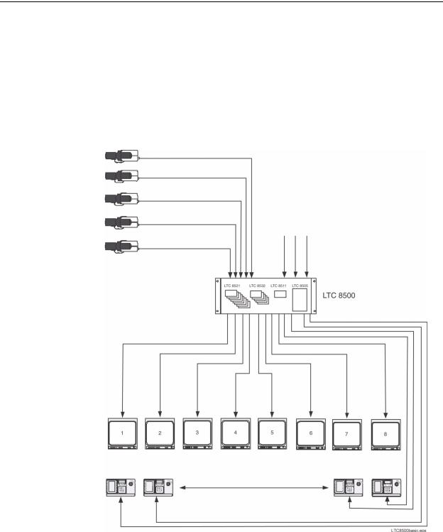
6.23 Logging Printer
|
An optional RS-232 serial printer may be connected to this system to provide a per- |
|
manent record of significant system status changes. Time and date is printed for sys- |
|
tem events such as alarms, start-up after power failure, sequence loading, operator |
|
log-on/log-off to keyboards, and download of information from the optional MCS. |
|
The printer may also be used to obtain hard copies of all system tables and |
|
sequences. |
NOTE |
The printer port does not provide a standardized pin-out connection. If desired, |
|
a cable can be made up at installation, by following the cable pin-out informa- |
|
tion provided at the end of this manual. |
|
LTC 8500 Series Video Switching Configuration |
Supports up to 64
Video Inputs
Main CPU Bay
Supports up to 8
Monitor Inputs
Maximum of 8 Allegiant Keyboards, up to 1.5 km (5000 ft) away using Optional Remote Hookup Kit
Figure 1: LTC 8500 Series Basic Video Switching Configuration
EN | 14 |
Bosch Security Systems | December 13, 2005 |
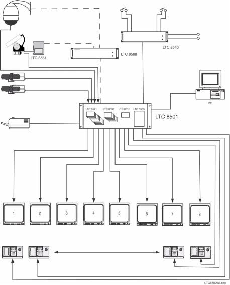
Logging Printer
LTC 8500 Series Full Capacity Video Switching Configuration
Typical AutoDome |
|
|
|
Camera |
|
8 Relay |
|
|
|
Outputs |
|
Receiver/Driver |
|
|
|
|
|
Optional LTC 8059/00 |
|
|
|
MCS or LTC 8850/00 |
|
|
Alarm |
GUI Software |
|
|
Package can be |
||
Signal |
Interface |
||
Run on a PC |
|||
Distribution |
Unit Sup- |
||
|
|||
Unit Supports |
ports up to |
|
|
up to 32 |
64 Separate |
|
|
Seperate |
Alarm Inputs |
||
Outputs |
|
|
|
Supports up to 64 |
|
RS-232 |
|
Video Inputs |
|
Data |
|
Main CPU Bay
Supports up to 8 Monitor Outputs
Maximum of 8 Allegiant Keyboards, up to 1.5 km (5000 ft) away using Optional Remote Hookup Kit
Figure 2: LTC 8500 Series Full Capacity Video Switching Configuration
EN | 15
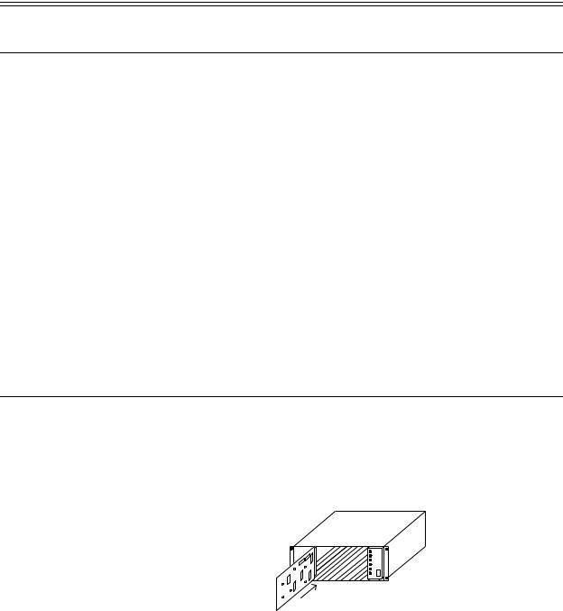
7Installation Procedure
7.1Main CPU Bay Installation
Before discarding the shipping cartons, verify that the various pieces of equipment have no evidence of carrier damage.
CAUTION |
Do not apply power to the equipment until instructed to do so. |
1.Remove the front panel of the main CPU bay by loosening the four (4) corner fasteners.
2.Install the power supply in far right position of the main CPU bay insuring proper alignment and seating of the module into the rear mating connector. Verify that the power supply ON/OFF switch is in the OFF position.
3.Install the four (4) screws and star washers (supplied) on the rear panel of the bay(s) surrounding the power supply line cord to fasten the power supply securely in place.
CAUTION If the Allegiant card cage is to be transported, the main power supply should be removed to prevent possible damage to the bay's internal parts.
4.If the bay(s) are to be installed into a standard 19-inch EIA rack, remove the four (4) rubber bumper foot pads found on the bottom of the bay before installing the unit in the rack. Four (4) holes are provided for mounting the bay(s) in the rack.
7.2Video Input Modules
Termination switches on the Video Input Modules (VIM) must be set to the correct position prior to installation. If necessary, see Section 7.6 “Termination Practices,” on page 18 prior to actually installing the VIM on this system.
The appropriate number of VIMs should be installed in the main bay starting with the left most slot. If less than full capacity is being used, the modules should be inserted in a left-to-right manner so that the lower camera numbers are used first.
Figure 3: Typical Video Input Module Insertion
The VIMs are identical and are interchangeable within the designated VIM slots without having to make any changes to the module.
EN | 16 |
Bosch Security Systems | December 13, 2005 |
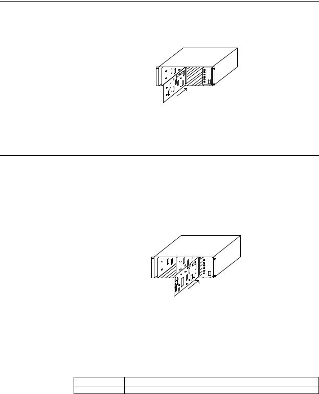
Video Output Modules
7.3Video Output Modules
Counting from left to right beginning with slot 9, install the appropriate number of Video Output Modules (VOM) into these slots. If fewer than the maximum number of VIMs are installed, there will be empty slots between the Input and the Output Modules, so make sure that the Output Modules are inserted into the correct slots.
Figure 4: Typical Video Output Module Insertion
All VOMs are identical and are interchangeable within the designated VOM slots.
7.4CPU Module
|
The slot to the left of the power supply in the main CPU bay is reserved for the sys- |
||
|
tem CPU module. |
||
NOTE |
The CPU module contains two (2) lithium batteries mounted on the component |
||
|
side of the printed circuit board. A red rectangular insulating tag may be |
||
|
installed in between the top of the batteries and the battery holder clip. This tag |
||
|
prevents battery drainage during stocking. Remove tag if so equipped. |
||
|
|
|
|
|
|
|
|
Figure 5: Typical CPU Module Insertion
Install the main bay CPU at this time.
The circuit board contains two (2) 8-position DIP switches for system configuration options. The DIP switches can be used to modify certain system operating conditions. Review the Factory Default Settings Section to determine if it is necessary to change the DIP switches from the factory default positions. For reference, the factory default settings are:
DIP Switch S1001 All OFF
DIP Switch S1002 Switch 5 ON, 7 ON, and 8 ON; All others OFF
EN | 17

7.5Camera and Monitor Video Connections
Refer to Figure 10 on page 28 for the next series of steps.
Connect the system cameras to the appropriate video inputs, but as a minimum connect one known operating camera to video input #1 on the rear of the main CPU bay. Use only those inputs that correspond to an installed VIM. Also connect desired monitors to the rear of the main CPU bay, ensuring to connect at least one monitor to video output #1. The video outputs are the left-most column of BNC connectors on the rear of the bay. Use only those outputs that correspond to an installed VOM.
7.6Termination Practices
Video from every video input signal must be “terminated” with a 75 ohm resistance. Each video line should be terminated exactly once. If video from a given camera is going to several different devices, only the last piece of equipment on the video line should be terminated. The following sections detail the ways that various Allegiant systems terminate video inputs.
LTC 8500 Series Video Terminations
Each LTC 8521/00 VIM card has an 8-position DIP switch for selecting the termination of each individual video line. To terminate an input line, make sure that the appropriate DIP switch on the VIM card is ON. If non-terminated operation is required for looping purposes, turn the switch OFF (Switch 1 corresponds to the first video input channel of the card).
The LTC 8500 Series main bays do not directly support video input looping connections. To attach video signals to inputs that will be looped on this system, a short piece of coax connected to a BNC "T" connector that has three (3) female ends is required.
Monitor Output Video Connections
Identical to camera inputs, monitor outputs on the Allegiant system are designed to be terminated. Each monitor output expects to be connected to a 75 ohm load. This is the regular load typically provided by a normal monitor. If a monitor output line is "looped" through several monitors or other equipment, the system installer should make sure that only the last unit on the line is terminated.
EN | 18 |
Bosch Security Systems | December 13, 2005 |

General Accessory Installation
8Optional Accessories Installation
8.1General Accessory Installation
There are many accessory products available for the Allegiant Series, including keyboards, alarm interface units, control code signal distribution units, etc. If applicable, these products can be installed at the same time as the main CPU bay installation, or postponed until later. In some cases, products are designed to be racked in close proximity to the main CPU bay, so appropriate rack space should be reserved.
Please refer to the instructions supplied with the specific accessory product for complete installation details.
8.2Logging Printer Option Installation
NOTE |
Although the exact installation procedure for each printer varies, the following |
|||
|
steps are generally required. Be sure to save the printer reference manual for |
|||
|
procedures not covered. |
|||
|
1. |
Switch the main power OFF to the printer. |
||
|
2. |
Install the ribbon cartridge and paper if necessary. |
||
|
3. |
Set any configuration switches for your particular printer to match the format |
||
|
|
provided by the Allegiant system. Note that the system communication protocol |
||
|
|
can be changed using the Keyboard User Functions (described later in this man- |
||
|
|
ual) with the optional Allegiant LTC 8059 MCS package. The factory default |
||
|
|
values are as follows: |
||
|
|
|
|
|
|
|
Baud rate -- |
19,200 |
|
|
|
|
|
|
|
|
Stop bits -- |
1 |
|
|
|
|
|
|
|
|
Data bits -- |
8 |
|
|
|
|
|
|
|
|
Parity -- |
None |
|
|
|
|
|
|
NOTE |
The required interconnect cable utilizes a custom pinout. Refer to the Appendix |
|||
|
Section of this manual for wiring details. |
|||
4.Attach the 25-pin male D-type connector side of the RS-232 cable to the connector on the printer.
5.Attach the 9-pin male connector side of the cable to the Allegiant CPU bay connector marked “PRINTER”.
6.Apply power to the printer.
7.Verify logging printer action by ‘loading’ a previously stored sequence into a monitor, activating an alarm, or performing a system reset. Any of these actions should cause printouts to occur.
EN | 19

8.3Computer Interface Installation
NOTE |
Although the exact installation procedure for each computer varies, the follow- |
|
|
ing steps are generally required. Be sure to save the computer reference man- |
|
|
ual for procedures not covered here. Switch the main power OFF to the |
|
|
computer. |
|
|
1. |
If using an Allegiant software package, attach the PC security key provided with |
|
|
the software to an available port on the computer. |
|
|
The supplied interconnect cable utilizes a custom pinout. If it ever becomes nec- |
|
|
essary to replace the cable, it can be ordered separately using part number: |
|
|
LTC 8506/00. Alternatively, a cable can be configured using the information |
|
|
found in the Appendix Section of this manual. |
|
2. |
Attach one end of the supplied RS-232 interface cable to the main Allegiant |
|
|
CPU bay connector marked Console (or another port that has been configured |
|
|
to operate as a console port). |
|
3. |
Attach the other end of the cable to an available serial port (COMM PORT 1 |
|
|
or COMM PORT 2) on the rear of the computer. |
|
4. |
Apply power to the computer and allow it to boot up its operating system |
|
|
before inserting the software disc. |
|
5. |
Refer to the applicable Allegiant software manual for complete programming |
|
|
instructions. |
EN | 20 |
Bosch Security Systems | December 13, 2005 |
 Loading...