


1365
IMPORTANT: IMPORTANT : IMPORTANTE:
Read Before Using Lire avant usage Leer antes de usar
For English Version Version française Versión en español
See page 2 Voir page 13 Ver la página 24
Operating/Safety Instructions
Consignes de fonctionnement/sécurité
Instrucciones de funcionamiento y seguridad
1-877-BOSCH99 (1-877-267-2499) www.boschtools.com
Call Toll Free for
Consumer Information
& Service Locations
Pour obtenir des informations
et les adresses de nos centres
de service après-vente,
appelez ce numéro gratuit
Llame gratis para
obtener información
para el consumidor y
ubicaciones de servicio
1364
1365
BM 1609929C59 06-10 :BM 1609929C59 06/10 6/24/10 8:10 AM Page 1

Read and understand all instructions. Failure to follow all instructions
listed below, may result in electric shock, fire and/or serious personal injury.
S
AVE THESE INSTRUCTIONS
-2-
Work Area
Keep your work area clean and well lit.
Clutter ed benches and dark area s invite
accidents.
Do not operate power tools in explosive
atmospheres, such as in the presence of
flammable liquids, gases, or dust. Power
tools create sparks which may ignite the dust
or fumes.
Keep by-standers, children, and visitors
aw ay wh ile o pera t ing a pow e r to o l.
Distractions can cause you to lose control.
Electrical Safety
Double Insulated tools are equipped with
a polarized plug (one blade is wider than
the other.) This plug will fit in a polarized
outlet only one way. If the plug does not
fit fully in the outlet, reverse the plug. If it
sti l l does not f i t , co n t a c t a qualifi e d
electrician to install a polarized outlet. Do
not change the plug in any way. Double
Insulation eliminates the need for the
three w i r e grounded power c o r d and
grounded power supp ly system. Be for e
plugging in the tool, be certain the outlet
voltage supplied is within the voltage marked
on the nameplate. Do not use “AC only” rated
tools with a DC power supply.
Av oid b ody c onta ct wi th gr ound ed
surfaces such as pipes, radiators, ranges
and refrigerators. There is an increased risk
of electric shock if your body is grounded. If
operating the power tool in damp locations is
unavoidable, a Ground Fault Circuit Interrupter
must be used to supply the power to your tool.
Electrician’s rubber gloves and footwear will
further enhance your personal safety.
Don't expose power tools to rain or wet
conditions. Water entering a power tool will
increase the risk of electric shock.
Do not abuse the cord. Never use the cord
to carry the tools or pull the plug from an
outlet. Keep cord away from heat, oil, sharp
edges or moving parts. Replace damaged
cords immediately. Damaged cords increase
the risk of electric shock.
When operating a power tool outside, use
an outdoor extension cord marked "W-A"
or "W." These cords are rated for outdoor use
and reduce the risk of electric shock. Refer to
“Recommended sizes of Extension Cords” in
the Accessory section of this manual.
Personal Safety
Stay alert, watch what you are doing and
us e c ommo n sens e w hen op erat ing a
power tool. Do not use tool while tired or
under the influence of drugs, alcohol, or
medication. A moment of inattention while
operating power tools may result in serious
personal injury.
Dress properly. Do not wear loose clothing
or jewelry. Contain long hair. Keep your
ha ir, cloth ing, and glov es aw ay from
moving parts. Loose clothes, jewelry, or
long hair can be caught in moving parts.
Keep handles dry, clean and free from oil and
grease.
Avoid accidental starting. Be sure switch is
“OFF” before plugging in. Carrying tools with
your finger on the switch or plugging in tools
that have the switch “ON” invites accidents.
Remove adjusting keys or wrenches before
turning the tool “ON”. A wrench or a key that
is left attached to a rotating part of the tool may
result in personal injury.
Do not overreach. Keep proper footing and
balance at all times. Proper footing and
balance enables better control of the tool in
unexpected situations.
Use safety equipment. Always wear eye
protection. Dust mask, non-skid safety shoes,
hard hat, or hearing protection must be used
for appropriate conditions.
Tool Use and Care
Us e c l amps or ot her pr a ctic al w ay t o
secure and support the workpiece to a
stable platform. Holding the work by hand or
against your body is unstable and may lead to
loss of control.
Do not force tool. Use the correct tool for
your application. The correct tool will do the
!
WARNING
Power Tool Safety Rules
BM 1609929C59 06-10 :BM 1609929C59 06/10 6/24/10 8:10 AM Page 2

-3-
Abrasive Cut-Off Machine Safety Rules
job better and safer at the rate for which it is
designed.
Do not use tool if switch does not turn it
“ON” or “OFF”. Any tool that cannot be
controlled with the switch is dangerous and
must be repaired.
Disconnect the plug from the power source
before making any adjustments, changing
accessories , or st ori ng th e too l. Such
preventive safety measures reduce the risk of
starting the tool accidentally.
Store idle tools out of reach of children and
ot her un trai n ed pe r sons . To ols ar e
dangerous in the hands of untrained users.
Maintain tools with care. Keep cutting tools
sharp and clean. Properly maintained tools,
with sharp cutting edges are less likely to bind
and are easier to control. Any alteration or
modification is a misuse and may result in a
dangerous condition.
Check for mi sal ignment o r b ind ing of
moving parts, breakage of parts, and any
other condition that may affect the tools
op erat i on. If damag ed, ha ve the tool
serviced before using. Many accidents are
caused by poorly maintained tools. Develop a
periodic maintenance schedule for your tool.
Us e only a cces sories th at are recommende d by the manufact ure r for yo ur
model. Accessories that may be suitable for
one tool, may become hazardous when used
on another tool.
Service
Tool service must be performed only by
qu alif i ed repai r pe r sonn el. Serv ice or
ma inte nance per form ed b y un quali fied
personnel could result in a risk of injury. For
example: internal wires may be misplaced or
pinched, safety guard return springs may be
improperly mounted.
When servicing a tool, use only identical
replacement parts. Follow instructions in
the Maintenance section of this manual.
Use of unauthorized parts or failure to follow
Maintenance Instructions may create a risk of
electric shock or injury . Certain cleaning
agents such as gasoline, carbon tetrachloride,
ammonia, etc. may damage plastic parts.
Always use wheel guard, foot plate and
auxiliary handle with this abrasive cut off
machin e . The gua r d must alw a y s be
secure l y a t t a ched to th e tool an d
positioned for maximum safety, so the
least amount of wheel is exposed on the
operators side of the tool. A guard protects
operator from broken wheel fragments. The
foo t plat e and auxili a r y han d l e pro v i d e
additional guarding, stability and control in
cut off applications.
Abrasive cut off wheels must be rated for
at least the speed recommended on the
to o l wa rning la b e l. Whe els a nd o t her
accessories running over rated speed can fly
apart and cause injury.
Hold tool by insulated gripping surfaces
when performing an operation where the
ab r a s i ve wh e els m a y co n t a c t hi d d en
wiring or its own cord. Contact with a “live”
wire will make exposed metal parts of the
tool “live” and shock the operator.
Always be certain that the wheel guard,
foot plate a n d aux i l i a r y handle a r e
reassembled and securely fastened to the
ma c h i ne w h e n ch a nging t he p o i n t of
operation from fire forward to fire reverse
or af t e r ch a n g ing the whe e l s . A tool
missing an essential safety component is
dangerous to operate.
Wear pr o p e r ap p a r e l while using an
abrasive cut off machine. Face shield or at
least s afe ty goggles, dust mask, leather
gloves and shop apron capable of stopping
small wheel or workpiece fragments.
This machine is not intended to be used
with Wet Diamond Wheels. Using water or
other liquid coolants with this machine may
result in electrocution or shock. Use of Dry
Diamond Wheels is acceptable.
Use only Type 1 abrasive cut off wheels
with the correct size arbor hole. Never use
damaged or incorrect wheel flanges or
round nut. Other types of wheels are not
intended to apply load on periphery and may
shatter. Wheels with arbor holes that do not
match the mounting hardware of the tool will
run eccentrically, vibrate excessively and will
cause loss of control.
BM 1609929C59 06-10 :BM 1609929C59 06/10 6/24/10 8:10 AM Page 3

Do not gr i n d on th e side of Ty p e 1
abrasive cut off wheels. Side forces applied
to these wheels may cause them to shatter.
Do not use this tool with “Woodcarving”
blade or standard wood cutting toothed
blades. These blades are not intended for
this machine and can create loss of control
during use.
Abrasive C ut Off W hee ls must have a
maximum safe operating speed greater
than the “no load RPM” marked on the
tool’s nameplate. Wheels running over the
rated speed can fly apart and cause injury.
Before each use inspect the cut off wheel
for chips and cracks. Do not use a wheel
that may be damaged. Install a new wheel
if tool was dropped. When installing a
new wheel carefully handle individual cut
off wheels to avoid chipping or cracking.
Run the tool at no load for one minute,
hold ing the tool in the dire ction away
from peo p l e . Wh e e l s wi t h fl a w s wi l l
normally break apart during this time .
Fragments from a wheel that bursts during
op erati on w ill fly aw ay a t great vel ocit y
possibly striking you or bystanders.
Do not use a cut off wheel that is larger
than the maximum recommended size for
your tool, or worn down damaged wheels
from larger abrasive cut off machines.
Whee ls intended f or larger tools are not
suitable for the higher speed of a smaller
tool, these wheels may easily burst and the
fragments strike you or bystanders.
Position the cord clear of the spinning
wheel. Do not wrap the cord around your
arm or wrist. If you lose control and have
the cord wrapped around your arm or wrist, it
may entrap you and cause injury.
Keep your body positioned to either side
of the wh e el, b ut n o t in li ne w i th t h e
wheel. It is important to support the tool
properly and to position your body such as to
minimize body exposure from the possible
wheel binding and the recoil of the tool.
Keep hands away from cutting area and
wheel . Ke e p y o u r s e c o n d h a n d o n
auxiliary handle. Hold the machine firmly
to prevent loss of control. NEVER place
your hand behind the wheel since the
machine may recoil over your hand. Do
not attempt to remove cut material when
wheel is moving. If both hands are holding
the machine, they cannot be cut by the wheel
Do not “jam” the abrasive wheel into the
work, ap p l y e x c e s s i v e p r e s s u r e o r
attempt to use large depths of cut while
using this machine. Let the rotating wheel
do the work, Abrasive Cut Off Machines are
intended to “cut” the material in a series of
shallow depth of cuts. See the instructions for
depth of cut later in this manual.
Avoid bouncing and snagging the wheel,
especially when working corners, sharp
edges etc. This can cause loss of control
and machine’s recoil.
Do not run the machine while carrying it
at your side. Accidental contact with the
spinni n g wh e e l could result in se r i o u s
personal injury.
Never lay the tool down until the motor
has come to a complete standstill. The
spinning wheel can grab the surface and pull
the tool out of your control.
Do not use the abrasive cut off machine
near flammable materials. Sparks from the
wheel could ignite these materials.
Never cut or attempt to cut magnesuum
with this tool. The dust generated when
cutting magnesuum is highly flammable and
may be explosive under certain conditions.
Regularly clean the tool’s air vents by
compressed air. Excessive accumulation of
powdered metal inside the motor housing
may cause electrical failures.
Causes and Operator Prevention of Recoil:
Recoil is a sudden reaction to a pinched,
bound or misa ligned rotat ing w heel. The
wheel may stall and cause an uncontrolled
machine to back out of the kerf toward the
operator when the machine is in the “fire
forward” position, if the machine is set in the
“reverse fire” position the machine may tend
to walk away from the operator.
If an abra s i ve w h e el o r di a m ond w h eel
becomes twisted or misaligned in the cut, the
side of the wheel that is entering into the
material can dig into the top surface of the
material causing the wheel to climb out or
recoil out of the kerf either toward or away
from the operator, depending on t he fire
forward or reverse fire orientation.
Abra sive whe els may also shat ter under
these conditions causing pieces or fragments
to strike or i m p a l e t h e o p erator and
bystanders. Recoil or shattered wheels are
the result of tool misuse and/or incorrect
operating procedures or conditions and can
-4-
BM 1609929C59 06-10 :BM 1609929C59 06/10 6/24/10 8:10 AM Page 4

be avoided by taking proper precautions as
given below:
Maintain a firm grip with both hands on
the machine handles and position your
body and arm to allow you to resist recoil
forces. Recoil forces can be controlled by
the operator, if proper precautions are taken.
When wheel is binding, or w h e n
interrupting a cut for any reason, release
the trigg e r a n d h o l d t h e m a c h i n e
motionless in the material until the wheel
comes to a complete stop. Never attempt
to r emo ve the mac hin e from t he work
while the wheel is in motion or recoil may
occur. Investigate and take corrective action
to eliminate the cause of wheel binding.
When r e s t a r t i n g a m a c h i n e i n a
workpiece, center the wheel in the kerf
and check that the sides of the wheel are
not engaged into the material. If wheel is
binding, it may walk up or recoil from the
workpiece as the machine is restarted.
Support large panels to minimize the risk
of wheel pinching and recoil. Large panels
tend to sag under their own weight. Supports
must be placed under the panel on b oth
sides, near the line of cut and near the edge
of the panel.
Wheel depth adjusting locking levers/nuts
must be tight and secure before making a
cut. If depth adjustment shifts while cutting, it
may cause binding and recoil. Using the
machi ne with an excessiv e d epth of cut
setting increases loading on the unit and
susceptibility to twisting of the wheel in the
kerf. It also increases the surface area of the
wheel available for pinching under wheel
twisting conditions or misalignment.
Use extra caution when making a “Pocket
Cut” into exist ing wal ls or other blind
areas. The protruding wheel may cut objects
that can cause recoil.
Some d u s t cr e a t e d by
po w e r sa n ding, s awing,
grinding, drilling, and other construction
activities contains chemicals known to
caus e cancer, b i r t h de f e c t s or o t h e r
reproductive harm. Some examples of
these chemicals are:
• Lead from lead-based paints,
• Crystalline silica from bricks and cement
and other masonry products, and
• Arsenic and chromium from chemically-
treated lumber.
Yo u r ri s k fr om these e xposure s va r ies,
depending on how often you do this type of
work . To reduce your exposure to these
chemicals: work in a well ventilated area, and
work with approved safety equipment, such
as thos e dus t mask s tha t are spec i a l ly
designed to filter out microscopic particles.
-5-
!
WARNING
BM 1609929C59 06-10 :BM 1609929C59 06/10 6/24/10 8:10 AM Page 5
-6-
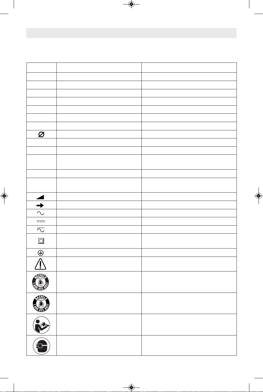
IMPORTANT: Some of the following symbols may be used on your tool. Please study them
and learn their meaning. Proper interpretation of these symbols will allow you to operate the
tool better and safer.
Symbol Name Designation/Explanation
V Volts Voltage (potential)
A Amperes Current
Hz Hertz Frequency (cycles per second)
W Watt Power
kg Kilograms Weight
min Minutes Time
s Seconds Time
Diameter Size of drill bits, grinding wheels, etc.
n
0
No load speed Rotational speed, at no load
n Rated speed Manufacturers rated speed
.../min Revolutions or reciprocation Revolutions, strokes, surface speed,
per minute orbits etc. per minute
0 Off position Zero speed, zero torque...
1, 2, 3, ... Selector settings Speed, torque or position settings.
I, II, III, Higher number means greater speed
Infinitely variable selector with off Speed is increasing from 0 setting
Arrow Action in the direction of arrow
Alternating current Type or a characteristic of current
Direct current Type or a characteristic of current
Alternating or direct current Type or a characteristic of current
Class II construction Designates Double Insulated
Construction tools.
Earthing terminal Grounding terminal
Warning symbol Alerts user to warning messages
Li-ion RBRC seal Designates Li-ion battery recycling
program
Ni-Cad RBRC seal Designates Ni-Cad battery recycling
program
Read manual symbol Alerts user to read manual
Wear eye protection symbol Alerts user to wear eye protection
Symbols
0
BM 1609929C59 06-10 :BM 1609929C59 06/10 6/24/10 8:10 AM Page 6
-7-
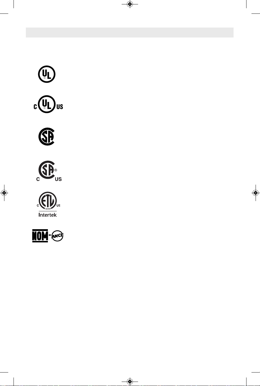
This symbol designates that this tool is listed by Underwriters Laboratories.
This symbol designates that this tool is listed by the Canadian Standards
Association.
This symbol designates that this tool is listed by the Canadian Standards
Association, to United States and Canadian Standards.
This symbol designates that this tool complies to NOM Mexican Standards.
Th
is
s
y
m
b
o
l d
e
s
ig
n
a
te
s
th
a
t th
is
to
o
l is
lis
te
d
b
y
Un
d
e
rwrite
rs
L
a
b
o
ra
to
rie
s
,
to
Un
ite
d
Sta
te
s
a
n
d
Ca
n
a
d
ia
n
Sta
n
d
a
rd
s
.
This symbol designates that this tool is listed by the Intertek Testing
Services, to United States and Canadian Standards.
Symbols (continued)
IMPORTANT: Some of the following symbols may be used on your tool. Please study them
and learn their meaning. Proper interpretation of these symbols will allow you to operate the
tool better and safer.
BM 1609929C59 06-10 :BM 1609929C59 06/10 6/24/10 8:10 AM Page 7
-8-
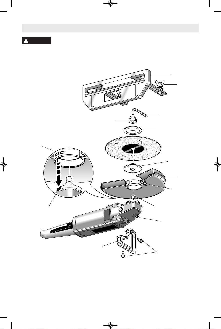
Functional Description and Specifications
Di s conne c t t h e pl ug f rom t he p o wer sou r ce b e fore mak i ng a n y
assembly, adjustments or changing accessories. Such preventive safety
measures reduce the risk of starting the tool accidentally.
!
WARNING
NOTE: For tool specifications refer to the nameplate on your tool.
Model No. 1364 1365
Maximum capacities
Abrasive wheel 12" 14"
Max. Cutting Depth 3-7/8" 4-7/8"
Arbor 7/8" 7/8"& 1"
No load RPM 5,000 4,300
AUXILIARY HANDLE
GUARD
FOOT PLATE
SPINDLE LOCK
ABRASIVE
WHEEL
GUARD
SECURING
CAP SCREW
MOUNTING BOLTS
OUTER
FLANGE
ALLEN
WRENCH
INNER
FLANGE
ARBOR
NUT
SPINDLE
LOCATING
NOTCHES
LOCATING
TABS
WING
NUT
Abrasive Cut-Off Machine
BM 1609929C59 06-10 :BM 1609929C59 06/10 6/24/10 8:10 AM Page 8
To prevent serious personal
injury, always disconnect the
plug from power source before changing
w
heels, or making any adjustments.
INSTALLING ABRASIVE WHEELS
Always use the arbor nut that has same
thread size as spindle.
1. Install inner fla nge onto spindle , with
re cess in bac k si de o f fl ange eng a ging
matching area on spindle.
2. Install abrasive wheel onto spindle.
3. Install outer flange with flat side out.
4. Thread arbor nut provided onto spindle
finger tight, depress spindle lock and tighten
wheel with the wrench provided.
Do not overtighten. Cracks in
the wh e e l can occur if
overtightened.
Do not depress spindle lock
while the tool is running.
Assembly
-9-
Al w a y s us e whe e l gu a r d ,
foot plate a n d auxiliar y
handle with this abrasive cut off machine.
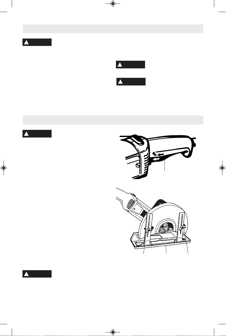
PADDLE SWITCH
WITH "LOCK-OFF" FEATURE
The Paddle Switch enables the operator to
control switch functions of "Lock-OFF", and
"ON/OFF".
TO UNLOCK SWITCH AND TURN TOOL
"ON": Push the paddle lever FORWARD
(toward the spindle) then squeeze the paddle
lever.
TO SWITCH TOOL "OFF": Release pressure
on the paddle lever. The switch is spring
loaded a nd will retu rn to "OFF" posi tion
automatically.
SIDE HANDLE
The side handle, used to guide and balance
the tool can be bolted to either side of the
sp indle ho using de pendi ng o n person al
preference and comfort. Always use the side
handle for maximum control and ease of
operation.
ADJUSTING DEPTH OF CUT
Loosen wing nuts, raise or lower foot plate to
desired depth, and securely tighten wing nuts
by hand.
To prevent r e c o i l and
damage to the tool, always
adjust the foot plate to a depth of so the inner
or ou t e r flanges ne v e r contacts the
workpiece surface.
!
WARNING
!
WARNING
Operating Instructions
!
WARNING
!
CAUTION
WING
NUT
WING
NUT
FOOT
PLATE
0
1
PADDLE
SWITCH
!
WARNING
BM 1609929C59 06-10 :BM 1609929C59 06/10 6/24/10 8:10 AM Page 9

-10-
OPERATING THE TOOL
Following a few simple tips will reduce wear
on the tool and it will reduce the chance of
injury to the operator.
This ma c h i n e i s n o t
intended to be used with
Wet Diamond Wheels. Using water or other
liquid coolants with this machine may result
in el e c t r o c u t i o n or shock. Us e of Dry
Diamond Wheels is acceptable.
APPLICATIONS
This tool is intended for cutting the following
materials.
1/8˝ maximum thick sheet steel.
Concrete cinder blocks and bricks.
Reinfo r c i n g r o d - g e n e r a l l y under 3/4˝
diameter.
1/8˝ concrete wire mesh.
Corrugated floor and ceiling forms (concrete
forms).
Electrical conduit 1/8˝ wall thickness.
1/8” maximum thick structural forms such as:
channels, angles, plate and etc.
ABRASIVE WHEELS
Use aluminum oxide wheels for cutting metal.
Use silicon carbide wheels for cutting
masonry.
Use dry diamond wheels for cutting concrete.
Dry diamond wheel stay cooler, clogs less
and last longer.
1 Before running a cut-off machine, inspect
the cutting wheel for chips or cracks. Replace
bad wheels immediately. New wheels should
be run in at no load or at least a minute in
direction away from the presence of other
people. Imperfect wheels will normally break
apart during this time.
2. An abrasive cut-off machine must NEVER
be opera ted without the a ttached guard
se c u red i n pla c e . Th e gu a r d sh o uld b e
rotated into the position where maximum
protection is provided for the operator from
sparks and wheel periphery.
3. Proper appar el f or operating the t ool
includes eye protection, leather gloves, dust
mask and a shop apron.
4. W i t h the tool in the "OFF" p o s i t i o n ,
be c ome f a miliar wit h ha n dling the too l .
Control the head of the tool with the side
handle. Control the cutting edge of the wheel
with the switch handle. Always use both
hands when operating the tool.
5. Never drop the tool. Set the tool down
gently, but never on the wheel.
6. CUTTING CONCRETE will throw large
amoun t s o f d u s t i n t o t h e s u r r o unding
area.
Prote c t i v e dust masks a r e str o n g l y
recommended for breathing protection for the
operator and other nearby workers.
7. Due to the size and weight of the cut-off
machine it is not recommended to be used
overhead or in any position that would not
allow proper control. Ladders or scaffolding
are not considered solid support structures.
8. Avoid overloading tool. Do not allow the
wheel to bind or stall. Many cuts, especially
int o soli d conc r e t e , re q u ire su c cessive
passes. Do not expose any more abrasive
wheel than necessary to cut with normal
amount of pressure applied to tool. Begin
cutting from the edge of the material, starting
with about 1" wheel exposed. Do not force
the tool; l oad it norm ally. Dependi ng on
mater i a l hardness a n d density, make
su ccess ively de eper pas ses u ntil cut is
complete.
FIRE FORWARD/FIRE REVERSE
Model s 13 6 4 & 1365 are sh i p p e d with
abrasive Cutoff Machine set up in fire forward
position. Both can be easily converted to fire
re v e r se po sition w ithout a ny ad ditional
accessories.
Fire forward position directs sparks, dust and
debris away from the operator.
Fire reverse position changes direction of
ro t ation so spa r ks, d ust a nd d ebris are
thrown toward the operator.
The proper fire position depends on how the
tool is being held, direction of travel, and
personal preference. Always remember the
reason for this feature is to direct sparks,
dust and debris away from the operator.
FIRE REVERSE APPLICATIONS
Below are a few examples of when you may
want to change your tool to the reverse fire
position.
• When cutting in a vertical position to direct
debris toward your feet instead of you face.
• When pulling the tool through the workpiece
instead of pushing the tool.
• When working in confined areas close to a
wall.
• Personal comfort.
!
WARNING
BM 1609929C59 06-10 :BM 1609929C59 06/10 6/24/10 8:10 AM Page 10

-11-
REVERSING FIRE DIRECTION
However we strongly recommend having this
ta sk perfo rmed by an au thor ized Bo sch
Service center.
1. Disconnect the plug from the power source.
2. Remove abrasive wheel.
3. Loosen wing nuts enough to allow screw
heads to slide out of foot plate mounting
holes provided in guard, and remove foot
plate.
4. Remove the four gear housing screws and
rotate gear housing 180˚. Replace housing
screws and securely tighten screws.
5. Loosen guard securing cap screw and
rotate guard for maximum wheel coverage
and securely tighten guard s ecuri ng cap
screw with the wrench provided.
6. Remove the auxiliary handle mounting
bolts, reposition handle using auxiliary hole in
handle, replace mounting bolts and securely
tighten handle.
7. Re-as semb le f oot plate and abras ive
wheel.
Service
Preventi ve maint ena nce
perfo r m e d by unauthorized per so n nel may result in misplacing
of internal wires and components which
could cause s e r i ous h a z a r d . We
recommend that all tool service be performed
by a Bosch Factory Service Center or Autho rized Bosch Service Station.
TOOL LUBRICATION
Your Bosch tool has been properly lubricated
and is ready to use. It is recommended that
tools with gears be regreased with a special
gear lubricant at every brush change.
CARBON BRUSHES
The brushes and commutator in your tool
have been engineered for many hours of
depend a b l e service. To maintain p e a k
efficiency of the motor, we recommend every
two to six months the brush es be examined.
Only genuine Bosch replace ment brushes
specially designed for your tool should be
used.
BEARINGS
After about 300-400 hours of operation, or at
every second brush change, the bearings
should be replaced at Bosch Factory Service
Center or Au thorized Bosch Service Station.
Bearings which become noisy (due to heavy
load or very abrasive material cut ting) should
be replaced at once to avoid overheating or
motor failure.
Cleaning
To avoid accidents always
dis connect the tool from
th e powe r sup p l y be f o re cl e aning o r
performing any main tenance. The tool may
be cleaned most effectively with compressed
dry air. Always wear safety gog gles when
cleaning tools with compressed air.
Ventilation openings and switch levers must
be kept clean and free of foreign matter. Do
not at tempt to clean by inserting pointed
objects through openings.
Ce rtai n clean ing age nts
and sol v e n t s d a m a g e
plastic parts. Some of these are: gasoline,
carbon tetrachlo ride, chlo rinated cleaning
solven t s , a m m o n i a a n d h o u s e hold
detergents that contain ammonia.
!
WARNING
!
WARNING
Maintenance
!
CAUTION
BM 1609929C59 06-10 :BM 1609929C59 06/10 6/24/10 8:10 AM Page 11
 Loading...