


OBJ_BUCH-1540-004.book Page 1 Monday, September 19, 2016 2:51 PM
Robert Bosch Power Tools GmbH
70538 Stuttgart
GERMANY
www.bosch-pt.com
1 609 92A 37G (2014.07) AS / 383 UNI
0 607 ...
...153 5.. | ... 154 1.. | ... 160 5.. | ... 161 1.. | ... 161 5 ..
de |
Originalbetriebsanleitung |
fi |
Alkuperäiset ohjeet |
kk |
Пайдалану нұсқаулығының |
en |
Original instructions |
el |
Πρωτότυπο οδηγιών χρήσης |
|
түпнұсқасы |
fr |
Notice originale |
tr |
Orijinal işletme talimatı |
ro |
Instrucţiuni originale |
es |
Manual original |
pl |
Instrukcja oryginalna |
bg |
Оригинална инструкция |
pt |
Manual original |
cs |
Původní návod k používání |
mk |
Оригинално упатство за работа |
it |
Istruzioni originali |
sk |
Pôvodný návod na použitie |
sr |
Originalno uputstvo za rad |
nl |
Oorspronkelijke |
hu |
Eredeti használati utasítás |
sl |
Izvirna navodila |
|
gebruiksaanwijzing |
ru |
Оригинальное руководство |
hr |
Originalne upute za rad |
da |
Original brugsanvisning |
|
по эксплуатации |
et |
Algupärane kasutusjuhend |
sv |
Bruksanvisning i original |
uk |
Оригінальна інструкція з |
lv |
Instrukcijas oriģinālvalodā |
no |
Original driftsinstruks |
|
експлуатації |
lt |
Originali instrukcija |
OBJ_BUCH-1540-004.book Page 2 Monday, September 19, 2016 2:59 PM
2 |
Deutsch. . . . . . . . . . . . . . . . . . . . . . . . . . . . . . . . . . . . . |
. . . . Seite |
6 |
English . . . . . . . . . . . . . . . . . . . . . . . . . . . . . . . . . . . . . |
. . . . .Page |
17 |
Français . . . . . . . . . . . . . . . . . . . . . . . . . . . . . . . . . . . . . |
. . . .Page |
29 |
Español . . . . . . . . . . . . . . . . . . . . . . . . . . . . . . . . . . . . . . |
. . Página |
40 |
Português . . . . . . . . . . . . . . . . . . . . . . . . . . . . . . . . . . . . |
. . Página |
51 |
Italiano . . . . . . . . . . . . . . . . . . . . . . . . . . . . . . . . . . . . . . |
. . Pagina |
62 |
Nederlands . . . . . . . . . . . . . . . . . . . . . . . . . . . . . . . . . . . |
. . Pagina |
73 |
Dansk . . . . . . . . . . . . . . . . . . . . . . . . . . . . . . . . . . . . . . . |
. . . . Side |
83 |
Svenska . . . . . . . . . . . . . . . . . . . . . . . . . . . . . . . . . . . . . |
. . . . Sida |
92 |
Norsk. . . . . . . . . . . . . . . . . . . . . . . . . . . . . . . . . . . . . . . . |
. . . . Side |
101 |
Suomi . . . . . . . . . . . . . . . . . . . . . . . . . . . . . . . . . . . . . . . |
. . . . Sivu |
110 |
Ελληνικά . . . . . . . . . . . . . . . . . . . . . . . . . . . . . . . . . . . . . |
. . Σελίδα |
119 |
Türkçe . . . . . . . . . . . . . . . . . . . . . . . . . . . . . . . . . . . . . . . |
. . . Sayfa |
129 |
Polski . . . . . . . . . . . . . . . . . . . . . . . . . . . . . . . . . . . . . . . |
. . Strona |
139 |
Česky . . . . . . . . . . . . . . . . . . . . . . . . . . . . . . . . . . . . . . . |
. . Strana |
150 |
Slovensky . . . . . . . . . . . . . . . . . . . . . . . . . . . . . . . . . . . . |
. . Strana |
159 |
Magyar . . . . . . . . . . . . . . . . . . . . . . . . . . . . . . . . . . . . . . |
. . . Oldal |
169 |
Русский . . . . . . . . . . . . . . . . . . . . . . . . . . . . . . . . . . . . |
Страница |
179 |
Українська . . . . . . . . . . . . . . . . . . . . . . . . . . . . . . . . . . . |
Сторінка |
191 |
Қазақша . . . . . . . . . . . . . . . . . . . . . . . . . . . . . . . . . . . . . |
. . . . . Бет |
202 |
Română . . . . . . . . . . . . . . . . . . . . . . . . . . . . . . . . . . . . . . |
. . Pagina |
213 |
Български . . . . . . . . . . . . . . . . . . . . . . . . . . . . . . . . . . |
Страница |
223 |
Македонски . . . . . . . . . . . . . . . . . . . . . . . . . . . . . . . . . |
. . Страна |
234 |
Srpski . . . . . . . . . . . . . . . . . . . . . . . . . . . . . . . . . . . . . . . |
. . Strana |
245 |
Slovensko . . . . . . . . . . . . . . . . . . . . . . . . . . . . . . . . . . . . |
. . . Stran |
254 |
Hrvatski. . . . . . . . . . . . . . . . . . . . . . . . . . . . . . . . . . . . . . |
. Stranica |
263 |
Eesti . . . . . . . . . . . . . . . . . . . . . . . . . . . . . . . . . . . . . . . . |
Lehekülg |
272 |
Latviešu . . . . . . . . . . . . . . . . . . . . . . . . . . . . . . . . . . . . . |
.Lappuse |
281 |
Lietuviškai. . . . . . . . . . . . . . . . . . . . . . . . . . . . . . . . . . . . |
. Puslapis |
292 |
. . . . . . . . . . . . . . . . . . . |
. . |
302 |
. . . . . . . . . . . . . . . . . . . |
. . . |
311 |
. . . . . . . . . . . . . . . . . . . . . . . |
. |
320 |
. . . . . . . . . . . . . . . . . . . . . . . . . . . . . |
. . . . 329 |
|
Bahasa Indonesia . . . . . . . . . . . . . . . . . . . . . . . . . . . . . . |
Halaman |
340 |
Tiếng Việt . . . . . . . . . . . . . . . . . . . . . . . . . . . . |
. Trang |
351 |
. . . . . . . . . . . . . . . . . . . . . . . . . . . . . |
. |
371 |
. . . . . . . . . . . . . . . . . . . . . . . . . . . . . |
. |
382 |
|
1 609 92A 37G | (19.9.16) |
|
|
Bosch Power Tools |
|||
|
|
|
|
|
|
|
|
|
|
|
|
|
|
|
|
|
|
|
|
|
|
|
|
OBJ_BUCH-1540-004.book Page 3 Monday, September 19, 2016 2:47 PM |
|
|
||||||
3 | |
|
|
|
|
|
|
|
|
|
|
3 |
|
4 |
0 607 154 101 |
|
||
|
|
|
|
|
|
|
||
|
|
|
|
|
|
5 |
|
|
1 |
2 |
|
|
|
|
|
3 |
0 607 161 1.. |
|
|
|
|
|
|
|
|
|
|
|
|
|
|
9 |
|
|
5 |
|
|
|
|
|
|
|
|
|
|
6 |
|
|
|
|
|
|
4 |
|
|
|
|
|
1 |
|
|
|
|
|
|
|
|
6 |
2 |
|
|
|
|
|
|
|
9 |
2 |
|
|
|
|
|
|
|
|
|
|
|
1 |
6 |
|
|
|
|
|
|
|
|
|
L |
E |
A |
N |
|
|
|
|
C |
|
|
|
|
|||
|
|
|
|
|
|
|||
|
|
|
|
|
|
|
||
|
|
|
|
1 |
6 |
7 |
|
|
|
|
|
|
|
|
|||
|
|
|
|
|
2 |
|
|
|
7 |
|
|
|
|
|
|
|
5 |
|
|
|
|
|
|
|
|
|
|
|
|
|
|
|
|
|
8 |
|
|
|
|
|
|
|
|
0 607 161 5.. |
8 |
5 |
|
|
|
|
|
|
|
|
0 607 153 5.. |
1 |
6 |
7 |
|
|
|
|
5 |
|
|
|
|
|
|
|
|
|
8 |
0 607 160 5.. |
|
|
|
|
|
1 609 92A 37G | (19.9.16) |
|
|
|
Bosch Power Tools |

OBJ_BUCH-1540-004.book Page 4 Monday, September 19, 2016 2:47 PM |
|
|
|
|||||
4 | |
|
|
|
|
|
|
|
|
A |
0 607 153 5.. |
|
|
|
0 607 161 5.. |
|||
|
|
4 |
|
|
|
|
|
|
|
|
|
|
|
|
|
4 |
|
|
|
|
|
|
2 |
|
|
|
|
|
|
|
10 |
|
|
|
|
|
|
N |
|
10 |
|
|
|
|
|
|
|
|
|
|
|
|
|
B |
|
|
|
|
C |
|
|
5 |
|
|
|
|
13 |
|
|
|
|
|
|
|
|
14 |
|
20 |
|
|
|
|
|
|
|
|
|
|
|
|
|
|
|
15 |
|
|
|
|
8 |
|
|
|
|
|
|
|
|
5 |
|
|
|
5 |
|
|
|
|
|
|
11 |
|
11 |
|
|
|
|
|
|
12 |
|
16 |
17 |
18 |
19 |
|
0 607 161 1.. |
|
12 |
||||||
|
|
|
|
|
|
|
||
0 607 161 5.. |
|
0 607 154 101 |
0 607 161 1.. |
|
|
|||
D |
|
|
21 11 |
22 |
|
|
|
|
20 |
8 |
|
|
|
|
|
||
|
|
|
|
|
|
20 |
||
|
|
|
|
|
|
|
|
|
|
|
5 |
|
|
|
|
|
5 |
|
|
|
|
|
|
|
|
21 |
|
|
|
|
|
|
|
|
11 |
|
|
|
|
|
|
|
|
22 |
|
|
0 607 161 1.. |
|
0 607 161 5.. |
|
|
|
|
1 609 92A 37G | (19.9.16) |
|
|
|
|
Bosch Power Tools |
|||
OBJ_BUCH-1540-004.book Page 5 Monday, September 19, 2016 2:47 PM |
|
|
|
||||
5 | |
|
|
|
|
|
|
|
E |
|
|
|
|
|
|
|
|
|
20 |
5 |
20 |
|
|
|
|
|
|
|
5 |
|
|
|
|
|
11 |
|
|
11 |
|
|
|
|
21 |
|
|
21 |
|
|
F |
|
|
|
G |
25 |
|
|
|
|
|
|
|
|
|
|
26 |
23 |
|
|
|
26 |
23 |
27 |
|
|
|
|
28 |
|
||
26 |
|
|
|
|
|
|
|
|
|
|
|
|
|
|
|
|
|
|
1 |
6 |
|
|
|
|
24 |
|
|
|
|
|
24 |
|
|
|
|
|
|
|
|
H |
0 607 154 101 |
|
I |
|
0 607 160 509 |
||
|
0 607 161 1.. |
|
|
|
|
0 607 160 511 |
|
3 |
|
|
|
|
|
|
|
7 |
|
|
7 |
|
|
|
|
0 607 153 5.. |
0 607 161 5.. |
|
29 |
||||
0 607 160 5.. |
|
|
|
|
|||
|
|
|
|
|
|
||
1 609 92A 37G | (19.9.16) |
|
|
|
|
|
Bosch Power Tools |
|

OBJ_BUCH-1540-004.book Page 6 Monday, September 19, 2016 2:47 PM
6 | Deutsch
Deutsch
Sicherheitshinweise
Allgemeine Sicherheitshinweise für Druckluftwerkzeuge
WARNUNG |
Lesen und beachten Sie vor dem Ein- |
|
bau, dem Betrieb, der Reparatur, der |
||
|
Wartung und dem Austausch von Zubehörteilen sowie vor der Arbeit in der Nähe des Druckluftwerkzeugs alle Hinweise. Bei Nichtbeachtung der folgenden Sicherheitshinweise können ernsthafte Verletzungen die Folge sein.
Bewahren Sie die Sicherheitshinweise gut auf und geben Sie sie der Bedienperson.
Arbeitsplatzsicherheit
Achten Sie auf Oberflächen, die durch den Gebrauch der Maschine rutschig geworden sein können, und auf durch den Luftoder den Hydraulikschlauch bedingte Stolpergefahren. Ausrutschen, Stolpern und Stürzen sind Hauptgründe für Verletzungen am Arbeitsplatz.
Arbeiten Sie mit dem Druckluftwerkzeug nicht in explosionsgefährdeter Umgebung, in der sich brennbare Flüssigkeiten, Gase oder Staub befinden. Beim Bearbeiten des Werkstücks können Funken entstehen, die den Staub oder die Dämpfe entzünden.
Halten Sie Zuschauer, Kinder und Besucher von Ihrem Arbeitsplatz fern, wenn Sie das Druckluftwerkzeug benutzen. Bei Ablenkung durch andere Personen können Sie die Kontrolle über das Druckluftwerkzeug verlieren.
Sicherheit von Druckluftwerkzeugen
Richten Sie den Luftstrom niemals auf sich selbst oder gegen andere Personen und leiten Sie kalte Luft von den Händen fort. Druckluft kann ernsthafte Verletzungen verursachen.
Kontrollieren Sie Anschlüsse und Versorgungsleitungen. Sämtliche Wartungseinheiten, Kupplungen und Schläuche müssen in Bezug auf Druck und Luftmenge entsprechend den technischen Daten ausgelegt sein. Zu geringer Druck beeinträchtigt die Funktion des Druckluftwerkzeugs, zu hoher Druck kann zu Sachschäden und zu Verletzungen führen.
Schützen Sie die Schläuche vor Knicken, Verengungen, Lösungsmitteln und scharfen Kanten. Halten Sie die Schläuche fern von Hitze, Öl und rotierenden Teilen. Ersetzen Sie einen beschädigten Schlauch unverzüglich. Eine schadhafte Versorgungsleitung kann zu einem herumschlagenden Druckluftschlauch führen und kann Verletzungen verursachen. Aufgewirbelter Staub oder Späne können schwere Augenverletzungen hervorrufen.
Achten Sie darauf, dass Schlauchschellen immer fest angezogen sind. Nicht fest gezogene oder beschädigte Schlauchschellen können die Luft unkontrolliert entweichen lassen.
Sicherheit von Personen
Seien Sie aufmerksam, achten Sie darauf, was Sie tun und gehen Sie mit Vernunft an die Arbeit mit einem Druckluftwerkzeug. Benutzen Sie kein Druckluftwerkzeug, wenn Sie müde sind oder unter dem Einfluss von Drogen, Alkohol oder Medikamenten stehen. Ein Moment der Unachtsamkeit beim Gebrauch des Druckluftwerkzeugs kann zu ernsthaften Verletzungen führen.
Tragen Sie persönliche Schutzausrüstung und immer eine Schutzbrille. Das Tragen persönlicher Schutzausrüstung, wie Atemschutz, rutschfeste Sicherheitsschuhe, Schutzhelm oder Gehörschutz, nach den Anweisungen Ihres Arbeitgebers oder wie nach den Arbeitsund Gesundheitsschutzvorschriften gefordert, verringert das Risiko von Verletzungen.
Vermeiden Sie eine unbeabsichtigte Inbetriebnahme. Vergewissern Sie sich, dass das Druckluftwerkzeug ausgeschaltet ist, bevor Sie es an die Luftversorgung anschließen, es aufnehmen oder tragen. Wenn Sie beim Tragen des Druckluftwerkzeugs den Finger am Ein-/Aus- schalter haben oder das Druckluftwerkzeug eingeschaltet an die Luftversorgung anschließen, kann dies zu Unfällen führen.
Entfernen Sie Einstellwerkzeuge, bevor Sie das Druckluftwerkzeug einschalten. Ein Einstellwerkzeug, das sich in einem drehenden Teil des Druckluftwerkzeugs befindet, kann zu Verletzungen führen.
Überschätzen Sie sich nicht. Sorgen Sie für einen sicheren Stand und halten Sie jederzeit das Gleichgewicht. Ein sicherer Stand und geeignete Körperhaltung lassen Sie das Druckluftwerkzeug in unerwarteten Situationen besser kontrollieren.
Tragen Sie geeignete Kleidung. Tragen Sie keine weite Kleidung oder Schmuck. Halten Sie Haare, Kleidung und Handschuhe fern von sich bewegenden Teilen. Lockere Kleidung, Schmuck oder lange Haare können von sich bewegenden Teilen erfasst werden.
Wenn Staubabsaugund -auffangeinrichtungen montiert werden können, vergewissern Sie sich, dass diese angeschlossen sind und richtig verwendet werden. Das Verwenden dieser Einrichtungen verringert Gefährdungen durch Staub.
Atmen Sie die Abluft nicht direkt ein. Vermeiden Sie es, die Abluft in die Augen zu bekommen. Die Abluft des Druckluftwerkzeugs kann Wasser, Öl, Metallpartikel und Verunreinigungen aus dem Kompressor enthalten. Dies kann Gesundheitsschäden verursachen.
Sorgfältiger Umgang mit und Gebrauch von Druckluftwerkzeugen
Benutzen Sie Spannvorrichtungen oder einen Schraubstock, um das Werkstück festzuhalten und abzustützen. Wenn Sie das Werkstück mit der Hand festhalten oder an den Körper drücken, können Sie das Druckluftwerkzeug nicht sicher bedienen.
Überlasten Sie das Druckluftwerkzeug nicht. Verwenden Sie für Ihre Arbeit das dafür bestimmte Druckluftwerkzeug. Mit dem passenden Druckluftwerkzeug arbei-
|
1 609 92A 37G | (19.9.16) |
|
|
Bosch Power Tools |
|||
|
|
|
|
|
|
|
|
|
|
|
|
|
|
|
|
|
|
|
|
|
|
|
|

OBJ_BUCH-1540-004.book Page 7 Monday, September 19, 2016 2:47 PM
ten Sie besser und sicherer im angegebenen Leistungsbereich.
Benutzen Sie kein Druckluftwerkzeug, dessen Ein- /Ausschalter defekt ist. Ein Druckluftwerkzeug, das sich nicht mehr einoder ausschalten lässt, ist gefährlich und muss repariert werden.
Unterbrechen Sie die Luftversorgung, bevor Sie Geräteeinstellungen vornehmen, Zubehörteile wechseln oder bei längerem Nichtgebrauch. Diese Vorsichtsmaßnahme verhindert den unbeabsichtigten Start des Druckluftwerkzeugs.
Bewahren Sie unbenutzte Druckluftwerkzeuge außerhalb der Reichweite von Kindern auf. Lassen Sie Personen das Druckluftwerkzeug nicht benutzen, die mit diesem nicht vertraut sind oder diese Anweisungen nicht gelesen haben. Druckluftwerkzeuge sind gefährlich, wenn sie von unerfahrenen Personen benutzt werden.
Pflegen Sie das Druckluftwerkzeug mit Sorgfalt. Kontrollieren Sie, ob bewegliche Geräteteile einwandfrei funktionieren und nicht klemmen, und ob Teile gebrochen oder so beschädigt sind, dass die Funktion des Druckluftwerkzeugs beeinträchtigt ist. Lassen Sie beschädigte Teile vor dem Einsatz des Druckluftwerkzeugs reparieren. Viele Unfälle haben ihre Ursache in schlecht gewarteten Druckluftwerkzeugen.
Halten Sie Schneidwerkzeuge scharf und sauber. Sorgfältig gepflegte Schneidwerkzeuge mit scharfen Schneidkanten verklemmen sich weniger und sind leichter zu führen.
Verwenden Sie Druckluftwerkzeug, Zubehör, Einsatzwerkzeuge usw. entsprechend diesen Anweisungen. Berücksichtigen Sie dabei die Arbeitsbedingungen und die auszuführende Tätigkeit. Damit werden Staubentwicklung, Schwingungen und Geräuschentwicklung soweit wie möglich reduziert.
Das Druckluftwerkzeug sollte ausschließlich von qualifizierten und geschulten Bedienern eingerichtet, eingestellt oder verwendet werden.
Das Druckluftwerkzeug darf nicht verändert werden.
Veränderungen können die Wirksamkeit der Sicherheitsmaßnahmen verringern und die Risiken für den Bediener erhöhen.
Service
Lassen Sie Ihr Druckluftwerkzeug nur von qualifiziertem Fachpersonal und nur mit Original-Ersatzteilen reparieren. Damit wird sichergestellt, dass die Sicherheit des Druckluftwerkzeugs erhalten bleibt.
Sicherheitshinweise für Druckluft-
Bohrmaschinen
Kontrollieren Sie, ob das Typenschild lesbar ist. Besorgen Sie sich gegebenenfalls Ersatz vom Hersteller.
Bei einem Bruch des Werkstücks oder eines der Zubehörteile oder gar des Druckluftwerkzeugs selbst können Teile mit hoher Geschwindigkeit herausgeschleudert werden.
Deutsch | 7
Beim Betrieb sowie bei Reparaturoder Wartungsarbeiten und beim Austausch von Zubehörteilen am Druckluftwerkzeug ist immer ein schlagfester Augenschutz zu tragen. Der Grad des erforderlichen Schutzes sollte für jeden einzelnen Einsatz gesondert bewertet werden.
Die Bediener und das Wartungspersonal müssen physisch in der Lage sein, die Größe, das Gewicht und die Leistung des Druckluftwerkzeugs zu handhaben.
Seien Sie auf unerwartete Bewegungen des Druckluftwerkzeugs gefasst, die infolge von Reaktionskräften oder dem Bruch des Einsatzwerkzeugs entstehen können. Halten Sie das Druckluftwerkzeug gut fest und bringen Sie Ihren Körper und Ihre Arme in eine Position, in der Sie diese Bewegungen abfangen können. Diese Vorsichtsmaßnahmen können Verletzungen vermeiden.
Schalten Sie das Druckluftwerkzeug sofort aus, wenn das Einsatzwerkzeug blockiert. Seien Sie auf hohe Reaktionsmomente gefasst, die einen Rückschlag verursachen. Das Einsatzwerkzeug blockiert, wenn:
–das Druckluftwerkzeug überlastet wird,
–es im zu bearbeitenden Werkstück verkantet oder
–es mit der Spitze durch den zu bearbeitenden Werkstoff hindurchgeht.
Verwenden Sie Hilfsmittel zur Aufnahme von Reaktionsmomenten, wie z.B. eine Abstützvorrichtung. Falls dies nicht möglich ist verwenden Sie einen Zusatzhandgriff.
Bringen Sie Ihre Hand nie in die Nähe sich drehender Einsatzwerkzeuge. Sie können sich verletzen.
Bei einer Unterbrechung der Luftversorgung oder reduziertem Betriebsdruck schalten Sie das Druckluftwerkzeug aus. Prüfen Sie den Betriebsdruck und starten Sie bei optimalem Betriebsdruck erneut.
Bei der Verwendung des Druckluftwerkzeugs kann der Bediener bei der Ausführung arbeitsbezogener Tätigkeiten unangenehme Empfindungen in den Händen, Armen, Schultern, im Halsbereich oder an anderen Körperteilen erfahren.
Nehmen Sie für die Arbeit mit diesem Druckluftwerkzeug eine bequeme Stellung ein, achten Sie auf sicheren Halt und vermeiden Sie ungünstige Positionen oder solche, bei denen es schwierig ist, das Gleichgewicht zu halten. Der Bediener sollte während lang dauernder Arbeiten die Körperhaltung verändern, was helfen kann, Unannehmlichkeiten und Ermüdung zu vermeiden.
Falls der Bediener Symptome wie z. B. andauerndes Unwohlsein, Beschwerden, Pochen, Schmerz, Kribbeln, Taubheit, Brennen oder Steifheit an sich wahrnimmt, sollten diese warnenden Anzeichen nicht ignoriert werden. Der Bediener sollte diese seinem Arbeitgeber mitteilen und einen qualifizierten Mediziner konsultieren.
Vorsicht! Einsatzwerkzeuge können bei längerem Betrieb des Druckluftwerkzeugs heiß werden. Verwenden Sie Schutzhandschuhe.
|
Bosch Power Tools |
|
|
1 609 92A 37G | (19.9.16) |
|||
|
|
|
|
|
|
|
|
|
|
|
|
|
|
|
|
|
|
|
|
|
|
|
|
OBJ_BUCH-1540-004.book Page 8 Monday, September 19, 2016 2:47 PM
8 | Deutsch
Verwenden Sie geeignete Suchgeräte, um verborgene Versorgungsleitungen aufzuspüren, oder ziehen Sie die örtliche Versorgungsgesellschaft hinzu. Kontakt mit Elektroleitungen kann zu Feuer und elektrischem Schlag führen. Beschädigung einer Gasleitung kann zur Explosion führen. Eindringen in eine Wasserleitung verursacht Sachbeschädigung.
Vermeiden Sie den Kontakt mit einer spannungsführenden Leitung. Das Druckluftwerkzeug ist nicht isoliert, und der Kontakt mit einer spannungsführenden Leitung kann zu einem elektrischen Schlag führen.
WARNUNG |
Der beim Schmirgeln, Sägen, Schlei- |
|
fen, BohrenundähnlichenTätigkeiten |
||
|
entstehende Staub kann krebserzeugend, fruchtschädigend oder erbgutverändernd wirken. Einige der in diesen Stäuben enthaltenen Stoffe sind:
–Blei in bleihaltigen Farben und Lacken;
–kristalline Kieselerde in Ziegeln, Zement und anderen Maurerarbeiten;
–Arsen und Chromat in chemisch behandeltem Holz.
Das Risiko einer Erkrankung hängt davon ab, wie oft Sie diesen Stoffen ausgesetzt sind. Um die Gefahr zu reduzieren, sollten Sie nur in gut belüfteten Räumen mit entsprechender Schutzausrüstung arbeiten (z.B. mit speziell konstruierten Atemschutzgeräten, die auch kleinste Staubpartikel herausfiltern).
Beim Arbeiten am Werkstück kann zusätzliche Lärmbelastung entstehen, die durch geeignete Maßnahmen vermieden werden kann, wie z.B. die Verwendung von Dämmstoffen beim Auftreten von Klingelgeräuschen am Werkstück.
Verfügt das Druckluftwerkzeug über einen Schalldämpfer, ist stets sicherzustellen, dass dieser beim Betrieb des Druckluftwerkzeugs vor Ort ist und sich in einem guten Arbeitszustand befindet.
Die Einwirkung von Schwingungen kann Schädigungen an den Nerven und Störungen der Blutzirkulation in Händen und Armen verursachen.
Tragen Sie enganliegende Handschuhe. Handgriffe von Druckluftwerkzeugen werden durch die Druckluftströmung kalt. Warme Hände sind unempfindlicher gegen Vibrationen. Weite Handschuhe können von rotierenden Teilen erfasst werden.
Falls Sie feststellen, dass die Haut an Ihren Fingern oder Händen taub wird, kribbelt, schmerzt oder sich weiß verfärbt, stellen Sie die Arbeit mit dem Druckluftwerkzeug ein, benachrichtigen Sie Ihren Arbeitgeber und konsultieren Sie einen Arzt.
Lassen Sie den Bohrer nicht auf dem Werkstück rattern. Dies kann zu einer erheblichen Verstärkung der Schwingungen führen.
Nutzen Sie zum Halten des Gewichts des Druckluftwerkzeugs, wenn möglich, einen Ständer, einen Federzug oder eine Ausgleichseinrichtung.
Halten Sie das Druckluftwerkzeug mit nicht allzu festem, aber sicherem Griff unter Einhaltung der erforderlichen Hand-Reaktionskräfte. Die Schwingungen können sich verstärken, je fester Sie das Werkzeug halten.
Falls Universal-Drehkupplungen (Klauenkupplungen) verwendet werden, müssen Arretierstifte eingesetzt werden. Verwenden Sie Whipcheck-Schlauchsicherun- gen, um Schutz für den Fall eines Versagens der Verbindung des Schlauchs mit dem Druckluftwerkzeug oder von Schläuchen untereinander zu bieten.
Tragen Sie das Druckluftwerkzeug niemals am Schlauch.
Symbole
Die nachfolgenden Symbole können für den Gebrauch Ihres Druckluftwerkzeugs von Bedeutung sein. Prägen Sie sich bitte die Symbole und ihre Bedeutung ein. Die richtige Interpretation der Symbole hilft Ihnen, das Druckluftwerkzeug besser und sicherer zu gebrauchen.
|
Symbol |
|
|
Bedeutung |
|
|
|
|
|
Lesen und beachten Sie vor dem |
|
|
|
|
|
||
|
|
|
|
Einbau, dem Betrieb, der Repara- |
|
|
|
|
|
||
|
|
|
|
tur, der Wartung und dem Aus- |
|
|
|
|
|
tausch von Zubehörteilen sowie |
|
|
|
|
|
vor der Arbeit in der Nähe des |
|
|
|
|
|
Druckluftwerkzeugs alle Hinweise. |
|
|
|
|
|
Bei Nichtbeachtung der Sicherheits- |
|
|
|
|
|
hinweise und Anweisungen können |
|
|
|
|
|
ernsthafte Verletzungen die Folge |
|
|
|
|
|
sein. |
|
|
|
|
|
Tragen Sie eine Schutzbrille. |
|
|
|
|
|
|
|
|
W |
Watt |
Leistung |
||
|
Nm |
Newtonmeter |
Energieeinheit |
||
|
(Drehmoment) |
||||
|
|
|
|
|
|
|
kg |
Kilogramm |
Masse, Gewicht |
||
|
lbs |
Pounds |
|||
|
|
||||
|
mm |
Millimeter |
Länge |
||
|
min |
Minuten |
Zeitspanne, Dauer |
||
|
s |
Sekunden |
|||
|
|
||||
|
|
|
|
|
|
|
min-1 |
Umdrehungen oder |
Leerlaufdrehzahl |
||
|
|
Bewegungen pro Minute |
|
||
|
bar |
bar |
Luftdruck |
||
|
psi |
pounds per square inch |
|||
|
|
||||
|
l/s |
Liter pro Sekunde |
Luftverbrauch |
||
|
cfm |
cubic feet/minute |
|||
|
|
||||
|
|
|
|
|
|
|
dB |
Dezibel |
Bes. Maß der |
||
|
relativen Lautstärke |
||||
|
|
|
|
|
|
|
1 609 92A 37G | (19.9.16) |
|
|
Bosch Power Tools |
|||
|
|
|
|
|
|
|
|
|
|
|
|
|
|
|
|
|
|
|
|
|
|
|
|
OBJ_BUCH-1540-004.book Page 9 Monday, September 19, 2016 2:47 PM
Symbol |
Bedeutung |
|
SWF |
Schnellwechselfutter |
|
|
Symbol für Innensechskant |
|
|
Symbol für Außenvierkant |
Werkzeugaufnahme |
|
US-Feingewinde |
|
UNF |
(Unified National Fine |
|
|
Thread Series) |
|
G |
Whitworth-Gewinde |
|
NPT |
|
Anschlussgewinde |
National pipe thread |
||
Produktund Leistungsbeschreibung
Lesen Sie alle Sicherheitshinweise und Anweisungen. Versäumnisse bei der Einhaltung der Sicherheitshinweise und Anweisungen können elektrischen Schlag, Brand und/oder schwere Verletzungen verursachen.
Bitte klappen Sie die Aufklappseite mit der Darstellung des Druckluftwerkzeugs auf, und lassen Sie diese Seite aufgeklappt, während Sie die Betriebsanleitung lesen.
Bestimmungsgemäßer Gebrauch
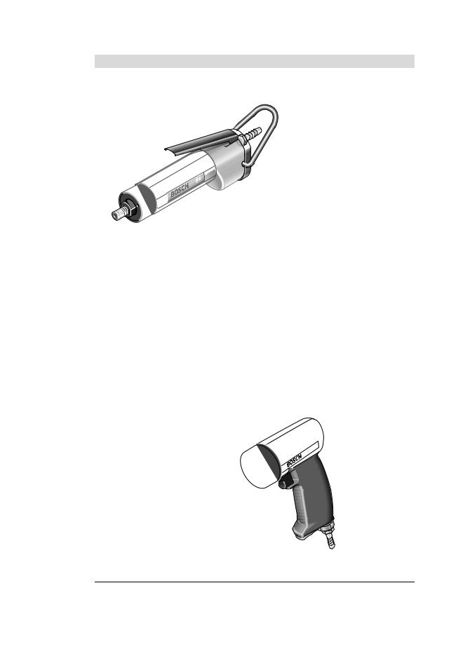
Das Druckluftwerkzeug ist bestimmt zum Bohren in Holz, Metall, Keramik und Kunststoff.
Abgebildete Komponenten
Die Nummerierung der abgebildeten Komponenten bezieht sich auf die Darstellungen auf der Grafikseite. Die Darstellungen sind teilweise schematisch und können bei Ihrem Druckluftwerkzeug abweichen.
1 Bohrspindel
2 Einspannbereich(z.B. für einen Zusatzgriff)
3 Ein-/Ausschalter (Hebel)
4 Aufhängebügel
5 Schlauchnippel
6 Schlüsselfläche an der Bohrspindel
7 Ein-/Ausschalter
8 Luftaustritt mit Schalldämpfer
9 Zusatzgriff*
10Befestigungsschlitze für Aufhängebügel
11Schlauchschelle
12Abluftschlauch
13Befestigungsschraube für Gehäusedeckel
14Gehäusedeckel
15Luftaustritt mit Sechskantmutter
16Dichtring
17Abluftset (dezentral)
18Anschlussstutzen am Abluftset
19Schalldämpfer am Abluftset
20Anschlussstutzen am Lufteinlass
21Zuluftschlauch
22Abluftschlauch zentral
23Zahnkranzbohrfutter
Deutsch | 9
24Schnellspannbohrfutter
25Bohrfutterschlüssel
26Werkzeugaufnahme
27Hintere Hülse
28Vordere Hülse
29Drehrichtungsumschalter
*Abgebildetes oder beschriebenes Zubehör gehört nicht zum Standard-Lieferumfang. Das vollständige Zubehör finden Sie in unserem Zubehörprogramm.
Konformitätserklärung
Wir erklären in alleiniger Verantwortung, dass das unter „Technische Daten“ beschriebene Produkt allen einschlägigen Bestimmungen der Richtlinie 2006/42/EG einschließlich ihrer Änderungen entspricht und mit folgenden Normen übereinstimmt: EN ISO 11148-3.
Technische Unterlagen (2006/42/EG) bei: Robert Bosch Power Tools GmbH, PT/ETM9, 70538 Stuttgart, GERMANY
Henk Becker |
Helmut Heinzelmann |
Executive Vice President |
Head of Product Certification |
Engineering |
PT/ETM9 |
Robert Bosch Power Tools GmbH
70538 Stuttgart, GERMANY
Stuttgart, 01.01.2017
Technische Daten
0 607 153 5../0 607 154 101
Diese Druckluftwerkzeuge gehören zur CLEAN-Baureihe.
Die Bosch CLEAN-Technik schont Anwender und Umwelt durch ölfreies Arbeiten sowie geringeren Luftund Energieverbrauch.
Ein Betrieb mit ölhaltiger Luft ist jedoch ebenfalls möglich.
consumption optimized – |
im Luftverbrauch optimiert |
|
lubrication free |
– |
ölfrei |
ergonomic |
– |
ergonomisch |
air tool |
– |
Druckluftwerkzeug |
noise reduction |
– |
reduzierter Geräuschpegel |
|
Bosch Power Tools |
|
|
1 609 92A 37G | (19.9.16) |
|||
|
|
|
|
|
|
|
|
|
|
|
|
|
|
|
|
|
|
|
|
|
|
|
|
OBJ_BUCH-1540-004.book Page 10 Monday, September 19, 2016 2:47 PM
10 | Deutsch
Druckluft-Bohrmaschine |
|
gerade Ausführung |
|
|
|
Pistolenform |
|
||||
Sachnummer |
|
|
0 607 154 ... |
0 607 161 ... |
|
|
|
0 607 153 ... |
|
||
|
|
|
... 101 |
... 100 |
|
... 101 |
... 102 |
... 103 |
... 520 |
|
... 523 |
Leerlaufdrehzahl |
|
min-1 |
3200 |
2560 |
|
1200 |
2560 |
1200 |
3700 |
|
3700 |
Abgabeleistung |
|
W |
120 |
400 |
|
400 |
400 |
400 |
180 |
|
180 |
|
|
Hp |
0,16 |
0,54 |
|
0,54 |
0,54 |
0,54 |
0,24 |
|
0,24 |
max. Bohrdurchmesser in Stahl |
|
mm |
4 |
8 |
|
10 |
8 |
10 |
4 |
|
4 |
|
|
in |
5/32" |
5/16" |
|
3/8" |
5/16" |
3/8" |
5/32" |
|
5/32" |
Lieferumfang |
|
|
– |
– |
|
– |
– |
– |
– |
|
|
– Schnellspannbohrfutter |
|
|
|
|
|
||||||
– Zahnkranzbohrfutter |
|
|
|
|
|
|
|
|
|
|
– |
Rechts-/Linkslauf |
|
|
– |
– |
|
– |
– |
– |
– |
|
– |
Bohrspindelgewinde |
|
|
|
– |
|
– |
– |
– |
|
|
|
– 3/8"-24 UNF-2A |
|
|
|
|
– |
|
– |
||||
– 1/2"-20 UNF-2A |
|
|
– |
|
|
|
|
|
|
|
|
Schlüsselfläche an der |
|
mm |
14 |
17 |
|
17 |
17 |
17 |
14 |
|
14 |
Bohrspindel |
|
|
|
||||||||
Spannhalsdurchmesser |
|
mm |
28 |
46 |
|
46 |
46 |
46 |
– |
|
– |
max. Arbeitsdruck am Werkzeug |
|
bar |
6,3 |
6,3 |
|
6,3 |
6,3 |
6,3 |
6,3 |
|
6,3 |
|
|
psi |
91 |
91 |
|
91 |
91 |
91 |
91 |
|
91 |
Anschlussgewinde des |
|
|
|
|
|
|
|
|
|
|
|
Schlauchanschlusses |
|
|
G 1/8" |
G 1/4" |
|
G 1/4" |
G 1/4" |
G 1/4" |
G 1/4" |
|
G 1/4" |
Lichte Schlauchweite |
|
mm |
6 |
10 |
|
10 |
10 |
10 |
10 |
|
10 |
Luftverbrauch im Leerlauf |
|
l/s |
3,4 |
15,5 |
|
16 |
15,5 |
15 |
7,8 |
|
8,5 |
|
|
cfm |
7,2 |
32,8 |
|
33,9 |
32,8 |
31,8 |
16,5 |
|
18 |
Gewicht entsprechend |
|
kg |
0,52 |
1,1 |
|
1,2 |
1,3 |
1,5 |
0,84 |
|
0,88 |
EPTA-Procedure 01:2014 |
|
lbs |
1,1 |
2,4 |
|
2,6 |
2,9 |
3,3 |
1,8 |
|
2,0 |
Geräusch-/Vibrationsinformation |
|
|
|
|
|
|
|
|
|
|
|
Geräuschemissionswerte ermittelt entsprechend EN ISO 15744. |
|
|
|
|
|
|
|||||
Der A-bewertete Geräuschpegel |
|
|
|
|
|
|
|
|
|
|
|
des Druckluftwerkzeugs beträgt |
|
|
|
|
|
|
|
|
|
|
|
typischerweise: |
|
|
|
|
|
|
|
|
|
|
|
Schalldruckpegel LpA |
dB(A) |
76 |
75 |
|
75 |
75 |
75 |
72 |
|
72 |
|
Schallleistungspegel LwA |
dB(A) |
87 |
86 |
|
86 |
86 |
86 |
83 |
|
83 |
|
Unsicherheit K |
dB |
2,5 |
2,5 |
|
2,5 |
2,5 |
2,5 |
2,5 |
|
2,5 |
|
Gehörschutz tragen!
Schwingungsgesamtwerte ah (Vektorsumme dreier Richtungen) und Unsicherheit K ermittelt entsprechend EN 28927:
Bohren in Metall: |
m/s2 |
4,5 |
9 |
9 |
9 |
9 |
< 2,5 |
< 2,5 |
a |
||||||||
h |
m/s2 |
0,9 |
1,4 |
1,4 |
1,4 |
1,4 |
1,5 |
1,5 |
K |
|
1 609 92A 37G | (19.9.16) |
|
|
Bosch Power Tools |
|||
|
|
|
|
|
|
|
|
|
|
|
|
|
|
|
|
|
|
|
|
|
|
|
|
OBJ_BUCH-1540-004.book Page 11 Monday, September 19, 2016 2:47 PM
Deutsch | 11
Druckluft-Bohrmaschine |
|
Pistolenform |
|
|
|
|
|
||
Sachnummer |
|
|
0 607 160 ... |
|
|
|
|
|
|
|
|
|
... 501 |
|
... 503 |
|
... 505 |
|
... 511 |
|
|
|
... 502 |
... 504 |
... 509 |
||||
Leerlaufdrehzahl |
|
min-1 |
2800 |
2800 |
2800 |
850 |
850 |
750 |
2200 |
Abgabeleistung |
|
W |
320 |
320 |
320 |
320 |
320 |
320 |
320 |
|
|
Hp |
0,43 |
0,43 |
0,43 |
0,43 |
0,43 |
0,30 |
0,30 |
max. Bohrdurchmesser in Stahl |
|
mm |
6 |
6 |
– |
10 |
10 |
10 |
10 |
|
|
in |
1/4" |
1/4" |
– |
3/8" |
3/8" |
3/8" |
3/8" |
Lieferumfang |
|
|
– |
– |
|
– |
– |
– |
– |
– ohne Bohrfutter |
|
|
|
||||||
– Schnellspannbohrfutter |
|
|
– |
|
– |
– |
|
– |
– |
– Zahnkranzbohrfutter |
|
|
|
– |
– |
|
– |
|
|
Rechts-/Linkslauf |
|
|
– |
– |
– |
– |
– |
|
|
Bohrspindelgewinde |
|
|
|
|
|
|
|
|
|
– 3/8"-24 UNF-2A |
|
|
|
|
|
|
|
|
|
Schlüsselfläche an der |
|
|
|
|
|
|
|
|
|
Bohrspindel |
|
mm |
12 |
12 |
12 |
14 |
14 |
14 |
12 |
Spannhalsdurchmesser |
|
mm |
– |
– |
– |
– |
– |
– |
– |
max. Arbeitsdruck am Werkzeug |
|
bar |
6,3 |
6,3 |
6,3 |
6,3 |
6,3 |
6,3 |
6,3 |
|
|
psi |
91 |
91 |
91 |
91 |
91 |
91 |
91 |
Anschlussgewinde des |
|
|
|
|
|
|
|
|
|
Schlauchanschlusses |
|
|
1/4" NPT |
1/4" NPT |
1/4" NPT |
1/4" NPT |
1/4" NPT |
1/4" NPT |
1/4" NPT |
Lichte Schlauchweite |
|
mm |
10 |
10 |
10 |
10 |
10 |
10 |
10 |
Luftverbrauch im Leerlauf |
|
l/s |
13 |
13 |
13 |
13 |
13 |
13 |
13 |
|
|
cfm |
27,5 |
27,5 |
27,5 |
27,5 |
27,5 |
27,5 |
27,5 |
Gewicht entsprechend |
|
kg |
0,81 |
0,87 |
0,71 |
0,87 |
1,0 |
0,96 |
0,91 |
EPTA-Procedure 01:2014 |
|
lbs |
1,8 |
2,0 |
1,5 |
2,0 |
1,4 |
1,4 |
2,0 |
Geräusch-/Vibrationsinformation |
|
|
|
|
|
|
|
|
|
Geräuschemissionswerte ermittelt entsprechend EN ISO 15744. |
|
|
|
|
|
||||
Der A-bewertete Geräuschpegel |
|
|
|
|
|
|
|
|
|
des Druckluftwerkzeugs beträgt |
|
|
|
|
|
|
|
|
|
typischerweise: |
|
|
|
|
|
|
|
|
|
Schalldruckpegel LpA |
dB(A) |
82 |
82 |
82 |
82 |
82 |
82 |
82 |
|
Schallleistungspegel LwA |
dB(A) |
93 |
93 |
93 |
93 |
93 |
93 |
93 |
|
Unsicherheit K |
dB |
2,5 |
2,5 |
2,5 |
2,5 |
2,5 |
2,5 |
2,5 |
|
Gehörschutz tragen!
Schwingungsgesamtwerte ah (Vektorsumme dreier Richtungen) und Unsicherheit K ermittelt entsprechend EN 28927:
Bohren in Metall: |
m/s2 |
|
|
|
|
|
|
|
a |
3,5 |
3,5 |
3,5 |
3,5 |
3,5 |
3,5 |
3,5 |
|
h |
m/s2 |
0,9 |
0,9 |
0,9 |
0,9 |
0,9 |
0,9 |
0,9 |
K |
|
Bosch Power Tools |
|
|
1 609 92A 37G | (19.9.16) |
|||
|
|
|
|
|
|
|
|
|
|
|
|
|
|
|
|
|
|
|
|
|
|
|
|
OBJ_BUCH-1540-004.book Page 12 Monday, September 19, 2016 2:47 PM
12 | Deutsch
Druckluft-Bohrmaschine |
|
Pistolenform |
|
|
|
|
|
|
|
|
Sachnummer |
|
0 607 161 ... |
|
|
|
|
|
|
|
|
|
|
... 500 |
|
... 502 |
|
... 504 |
|
... 506 |
|
|
|
|
... 501 |
... 503 |
... 505 |
... 507 |
|||||
Leerlaufdrehzahl |
min-1 |
2560 |
|
1200 |
800 |
640 |
2560 |
1200 |
800 |
640 |
Abgabeleistung |
W |
400 |
|
400 |
400 |
400 |
400 |
400 |
400 |
400 |
|
Hp |
0,54 |
|
0,54 |
0,54 |
0,54 |
0,54 |
0,54 |
0,54 |
0,54 |
max. Bohrdurchmesser in Stahl |
mm |
8 |
|
10 |
13 |
13 |
8 |
10 |
13 |
13 |
|
in |
5/16" |
|
3/8" |
1/2" |
1/2" |
5/16" |
3/8" |
1/2" |
1/2" |
Lieferumfang |
|
– |
|
– |
– |
– |
|
|
|
|
– Schnellspannbohrfutter |
|
|
|
|
|
|
||||
– Zahnkranzbohrfutter |
|
|
|
|
|
|
– |
– |
– |
– |
Rechts-/Linkslauf |
|
– |
|
– |
– |
– |
– |
– |
– |
– |
Bohrspindelgewinde |
|
|
|
|
|
|
|
|
|
|
– 1/2"-20 UNF-2A |
|
|
|
|
|
|
|
|
|
|
Schlüsselfläche an der |
mm |
17 |
|
17 |
17 |
17 |
17 |
17 |
17 |
17 |
Borspindel |
|
|||||||||
Spannhalsdurchmesser |
mm |
48 |
|
48 |
48 |
48 |
48 |
48 |
48 |
48 |
max. Arbeitsdruck am |
bar |
6,3 |
|
6,3 |
6,3 |
6,3 |
6,3 |
6,3 |
6,3 |
6,3 |
Werkzeug |
psi |
91 |
|
91 |
91 |
91 |
91 |
91 |
91 |
91 |
Anschlussgewinde des |
|
|
|
|
|
|
|
|
|
|
Schlauchanschlusses |
|
G 1/4" |
|
G 1/4" |
G 1/4" |
G 1/4" |
G 1/4" |
G 1/4" |
G 1/4" |
G 1/4" |
Lichte Schlauchweite |
mm |
10 |
|
10 |
10 |
10 |
10 |
10 |
10 |
10 |
Luftverbrauch im Leerlauf |
l/s |
14 |
|
14 |
14 |
14,2 |
14 |
12 |
14 |
14 |
|
cfm |
29,6 |
|
29,6 |
29,6 |
30 |
29,6 |
25,4 |
29,6 |
29,6 |
Gewicht entsprechend |
kg |
1,1 |
|
1,3 |
1,45 |
1,5 |
1,3 |
1,5 |
1,5 |
1,6 |
EPTA-Procedure 01:2014 |
lbs |
2,4 |
|
2,9 |
3,2 |
3,3 |
2,9 |
3,3 |
3,3 |
3,5 |
Geräusch-/Vibrationsinformation |
|
|
|
|
|
|
|
|
|
|
Geräuschemissionswerte ermittelt entsprechend EN ISO 15744. |
|
|
|
|
|
|||||
Der A-bewertete Geräusch- |
|
|
|
|
|
|
|
|
|
|
pegel des Druckluftwerkzeugs |
|
|
|
|
|
|
|
|
|
|
beträgt typischerweise: |
|
|
|
|
|
|
|
|
|
|
Schalldruckpegel LpA |
dB(A) |
73 |
|
73 |
73 |
73 |
73 |
73 |
73 |
73 |
Schallleistungspegel LwA |
dB(A) |
84 |
|
84 |
84 |
84 |
84 |
84 |
84 |
84 |
Unsicherheit K |
dB |
2,5 |
|
2,5 |
2,5 |
2,5 |
2,5 |
2,5 |
2,5 |
2,5 |
Gehörschutz tragen!
Schwingungsgesamtwerte ah (Vektorsumme dreier Richtungen) und Unsicherheit K ermittelt entsprechend EN 28927:
Bohren in Metall: |
m/s2 |
|
|
|
|
|
|
|
|
a |
3,5 |
3,5 |
3,5 |
3,5 |
3,5 |
3,5 |
3,5 |
3,5 |
|
h |
m/s2 |
0,8 |
0,8 |
0,8 |
0,8 |
0,8 |
0,8 |
0,8 |
0,8 |
K |
Der in diesen Anweisungen angegebene Schwingungspegel ist entsprechend einem in EN ISO 11148 genormten Messverfahren gemessen worden und kann für den Vergleich von Druckluftwerkzeugen miteinander verwendet werden. Er eignet sich auch für eine vorläufige Einschätzung der Schwingungsbelastung.
Der angegebene Schwingungspegel repräsentiert die hauptsächlichen Anwendungen des Druckluftwerkzeugs. Wenn allerdings das Druckluftwerkzeug für andere Anwendungen, mit unterschiedlichen Zubehören, mit abweichenden Einsatzwerkzeugen oder ungenügender Wartung eingesetzt wird, kann der Schwingungspegel abweichen. Dies kann die Schwingungsbelastung über den gesamten Arbeitszeitraum deutlich erhöhen.
Für eine genaue Abschätzung der Schwingungsbelastung sollten auch die Zeiten berücksichtigt werden, in denen das Druckluftwerkzeug abgeschaltet ist oder zwar läuft, aber nicht tatsächlich im Einsatz ist. Dies kann die Schwingungsbelastung über den gesamten Arbeitszeitraum deutlich reduzieren.
Legen Sie zusätzliche Sicherheitsmaßnahmen zum Schutz des Bedieners vor der Wirkung von Schwingungen fest wie zum Beispiel: Wartung von Druckluftwerkzeug und Einsatzwerkzeugen, Warmhalten der Hände, Organisation der Arbeitsabläufe.
|
1 609 92A 37G | (19.9.16) |
|
|
Bosch Power Tools |
|||
|
|
|
|
|
|
|
|
|
|
|
|
|
|
|
|
|
|
|
|
|
|
|
|

OBJ_BUCH-1540-004.book Page 13 Monday, September 19, 2016 2:47 PM
Montage
Aufhängeund Einspannvorrichtung
Aufhängevorrichtung (siehe Bild A)
Wenn Sie das Druckluftwerkzeug in einer Aufhängeoder Einspannvorrichtung betreiben wollen, achten Sie darauf, es erst in der Vorrichtung zu befestigen, bevor Sie es an die Luftversorgung anschließen. Dadurch vermeiden Sie, es unbeabsichtigt in Betrieb zu nehmen.
Mit dem Aufhängebügel 4 können Sie das Druckluftwerkzeug an einer Aufhängevorrichtung befestigen.
–0 607 153 5..
Setzen Sie den Aufhängebügel 4 auf das Druckluftwerkzeug auf, und lassen Sie ihn in die Schlitze 10 einrasten.
Je nach Schwerpunkt des Druckluftwerkzeugs können Sie entweder die vorderen oder hinteren Schlitze verwenden.
–0 607 161 5..
Stecken Sie den Aufhängebügel 4 auf den Einspannbereich 2.
Kontrollieren Sie regelmäßig den Zustand des Aufhängebügels und der Haken in der Aufhängevorrichtung.
Einspannvorrichtung
0 607 154 101/0 607 161 1../0 607 161 5..
–Im angegebenen Einspannbereich 2 können Sie das Druckluftwerkzeug in einer Einspannvorrichtung befestigen. Nutzen Sie möglichst den gesamten Einspannbereich. Je geringer der Einspannbereich, desto stärker wirken die Spannkräfte.
Überlasten Sie den Einspannbereich nicht.
Zusatzgriff montieren
0 607 160 5../0 607 161 1../0 607 161 5..
– Schieben Sie den Zusatzgriff 9 auf den Einspannbereich 2.
Sie können den Zusatzgriff 9 beliebig schwenken, um eine sichere und ermüdungsarme Arbeitshaltung zu erreichen.
–Drehen Sie die Flügelschraube für die Zusatzgriffverstellung entgegen dem Uhrzeigersinn und schwenken Sie den Zusatzgriff 9 in die gewünschte Position. Danach drehen Sie die Flügelschraube im Uhrzeigersinn wieder fest.
Abluftführung
Mit einer Abluftführung können Sie die Abluft durch einen Abluftschlauch von Ihrem Arbeitsplatz wegleiten und gleichzeitig eine optimale Schalldämpfung erreichen. Zudem verbessern Sie Ihre Arbeitsbedingungen, da Ihr Arbeitsplatz nicht mehr von ölhaltiger Luft verschmutzt werden kann oder Staub bzw. Späne aufgewirbelt werden.
Dezentrale Abluftführung (siehe Bild B) 0 607 161 1../0 607 161 5..
–Schrauben Sie den Schalldämpfer am Luftaustritt 8 heraus, und ersetzen Sie ihn durch einen Schlauchnippel 5.
–Lockern Sie die Schlauchschelle 11 des Abluftschlauches 12, und befestigen Sie den Abluftschlauch über dem Schlauchnippel 5, indem Sie die Schlauchschelle fest anziehen.
Deutsch | 13
0 607 153 5../0 607 154 101
Die Abluftführung sollte vor dem Anschluss an die Luftversorgung montiert werden, da der Gehäusedeckel 14 entfernt werden muss.
Sie können die Abluft in einen Abluftbehälter leiten.
–Schrauben Sie die drei Befestigungsschrauben 13 auf, und entfernen Sie den Gehäusedeckel 14.
–Tauschen Sie nun den Schalldämpfer gegen die Sechskantmutter 15 aus und befestigen Sie den Gehäusedeckel wieder mit den drei Befestigungsschrauben.
–Schrauben Sie den Schlauchnippel 5 in die Sechskantmutter 15 am Luftaustritt.
–Lockern Sie die Schlauchschelle 11 des Abluftschlauches 12, und befestigen Sie den Abluftschlauch über dem Schlauchnippel 5, indem Sie die Schlauchschelle fest anziehen.
Dezentrale Abluftführung mit Abluftset (siehe Bild C) 0 607 161 1..
Sie können die Abluft in einen Abluftbehälter leiten, indem Sie ein dezentrales Abluftset 17 befestigen.
Hinweis: Achten Sie darauf, dass der Schlauchnippel 5 nicht in den Anschlussstutzen 20 am Lufteinlass eingeschraubt ist und der Dichtring 16 in der Vertiefung zwischen Gehäuse und Abluftset 17 liegt, damit die ausströmende Luft nur zum Abluftschlauch 12 entweichen kann.
–Schrauben Sie den Anschlussstutzen 18 des Abluftsets fest in den Anschlussstutzen 20 am Lufteinlass und anschließend den Schlauchnippel 5 auf den Anschlussstutzen 18.
–Ersetzen Sie den Schalldämpfer19 am Abluftset durch den Schlauchnippel des Abluftsets.
–Lockern Sie die Schlauchschelle 11 des Abluftschlauches 12, und befestigen Sie den Abluftschlauch über dem Schlauchnippel 5, indem Sie die Schlauchschelle fest anziehen.
Zentrale Abluftführung (siehe Bild D) 0 607 161 1../0 607 161 5..
–Lockern Sie die Schlauchschelle 11 des Zuluftschlauches 21, und befestigen Sie den Zuluftschlauch über dem Schlauchnippel 5, indem Sie die Schlauchschelle fest anziehen.
–Stülpen Sie den Abluftschlauch (zentral) 22, der die Abluft von Ihrem Arbeitsplatz wegleitet, über den Zuluftschlauch 21. Schließen Sie das Druckluftwerkzeug dann an die Luftversorgung an (siehe „Anschluss an die Luftversorgung“, Seite 14) und ziehen Sie den Abluftschlauch (zentral) 22 über den montierten Zuluftschlauch auf das Geräteende.
Anschluss an die Luftversorgung (siehe Bild E)
Achten Sie darauf, dass der Luftdruck nicht niedriger als 6,3 bar (91 psi) ist, da das Druckluftwerkzeug für diesen Betriebsdruck ausgelegt ist.
Für eine maximale Leistung müssen die Werte für die lichte Schlauchweite sowie die Anschlussgewinde, wie in der Tabelle „Technische Daten“ angegeben, eingehalten werden. Zur
|
Bosch Power Tools |
|
|
1 609 92A 37G | (19.9.16) |
|||
|
|
|
|
|
|
|
|
|
|
|
|
|
|
|
|
|
|
|
|
|
|
|
|

OBJ_BUCH-1540-004.book Page 14 Monday, September 19, 2016 2:47 PM
14 | Deutsch
Erhaltung der vollen Leistung nur Schläuche bis maximal 4 m Länge verwenden.
Die zugeführte Druckluft muss frei von Fremdkörpern und Feuchtigkeit sein, um das Druckluftwerkzeug vor Beschädigung, Verschmutzung und Rostbildung zu schützen.
Hinweis: Die Verwendung einer Druckluft-Wartungseinheit ist notwendig. Diese gewährleistet eine einwandfreie Funktion der Druckluftwerkzeuge.
Beachten Sie die Betriebsanleitung der Wartungseinheit.
Sämtliche Armaturen, Verbindungsleitungen und Schläuche müssen dem Druck und der erforderlichen Luftmenge entsprechend ausgelegt sein.
Vermeiden Sie Verengungen der Zuleitungen, z.B. durch Quetschen, Knicken oder Zerren!
Prüfen Sie im Zweifelsfall den Druck am Lufteintritt mit einem Manometer bei eingeschaltetem Druckluftwerkzeug.
Anschluss der Luftversorgung an das Druckluftwerkzeug
–Schrauben Sie einen Schlauchnippel 5 in den Anschlussstutzen am Lufteinlass 20 ein.
Um Beschädigungen an innen liegenden Ventilteilen des Druckluftwerkzeugs zu vermeiden, sollten Sie beim Einund Ausschrauben des Schlauchnippels 5 an dem vorstehenden Anschlussstutzen des Lufteinlasses 20 mit einem Gabelschlüssel (Schlüsselweite 22 mm) gegenhalten.
–Lockern Sie die Schlauchschellen 11 des Zuluftschlauches 21, und befestigen Sie den Zuluftschlauch über dem Schlauchnippel 5, indem Sie die Schlauchschelle fest anziehen.
Hinweis: Befestigen Sie den Zuluftschlauch immer erst am Druckluftwerkzeug, dann an der Wartungseinheit.
Bohrfutter montieren (siehe Bild F)
–Halten Sie die Bohrspindel 1 an der Schlüsselfläche 6 mit einem passenden Gabelschlüssel fest und schrauben Sie das Zahnkranzbohrfutter 23 oder das Schnellspannbohrfutter 24 auf die Bohrspindel auf.
Das Bohrfutter muss mit einem Anzugsdrehmoment von ca. 20–25 Nm festgezogen werden.
Zahnkranzbohrfutter wechseln
–Halten Sie die Bohrspindel 1 an der Schlüsselfläche mit einem passenden Gabelschlüssel fest.
–Stecken Sie den Bohrfutterschlüssel 25 in eine der drei Bohrungen am Zahnkranzbohrfutter 23 und lösen Sie durch Linksdrehen das Bohrfutter.
Hinweis: Ein fest sitzendes Bohrfutter lösen Sie, indem Sie mit einem Innensechskantschlüssel in der Werkzeugaufnahme 26 gegenhalten.
Schnellspannbohrfutter wechseln
–Legen Sie das Druckluftwerkzeug auf eine standfeste Unterlage (z.B. Werkbank).
–Halten Sie die Bohrspindel 1 an der Schlüsselfläche 6 mit einem passenden Gabelschlüssel fest und lösen Sie durch Linksdrehen das Schnellspannbohrfutter 24 von der Bohrspindel.
Hinweis: Ein fest sitzendes Bohrfutter lösen Sie, indem Sie mit einem Innensechskantschlüssel in der Werkzeugaufnahme 26 gegenhalten.
Werkzeugwechsel (siehe Bild G)
Zahnkranzbohrfutter
–Öffnen Sie das Zahnkranzbohrfutter 23 durch Drehen, bis das Werkzeug eingesetzt werden kann. Setzen Sie das Werkzeug ein.
–Stecken Sie den Bohrfutterschlüssel 25 in die entsprechenden Bohrungen des Zahnkranzbohrfutters 23 und spannen Sie das Werkzeug gleichmäßig fest.
Einsatzwerkzeug entnehmen:
–Drehen Sie die Hülse des Zahnkranzbohrfutters 23 mithilfe des Bohrfutterschlüssels entgegen dem Uhrzeigersinn, bis das Einsatzwerkzeug entnommen werden kann.
Schnellspannbohrfutter
–Halten Sie die hintere Hülse 27 des Schnellspannbohrfutters 24 fest und drehen Sie die vordere Hülse 28 entgegen dem Uhrzeigersinn, bis das Werkzeug eingesetzt werden kann. Setzen Sie das Werkzeug ein.
–Halten Sie die hintere Hülse 27 des Schnellspannbohrfutters 24 fest und drehen Sie die vordere Hülse 28 im Uhrzeigersinn von Hand kräftig zu, bis ein Klicken zu hören ist. Das Bohrfutter wird dadurch automatisch verriegelt.
Einsatzwerkzeug entnehmen:
–Die Verriegelung löst sich wieder, wenn Sie zum Entfernen des Werkzeuges die vordere Hülse 28 in Gegenrichtung drehen.
Betrieb
Inbetriebnahme
Das Druckluftwerkzeug arbeitet optimal bei einem Arbeitsdruck von 6,3 bar (91 psi), gemessen am Lufteintritt bei eingeschaltetem Druckluftwerkzeug.
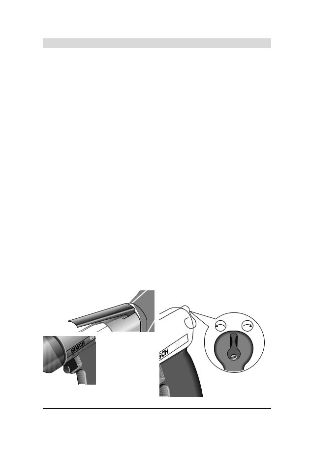
Ein-/Ausschalten (siehe Bild H)
Hinweis: Läuft das Druckluftwerkzeug, z.B. nach längerer Ruhezeit, nicht an, unterbrechen Sie die Luftversorgung, und drehen Sie an der Werkzeugaufnahme 26 den Motor mehrmals durch. Dadurch werden Adhäsionskräfte beseitigt.
Um Energie zu sparen, schalten Sie das Druckluftwerkzeug nur ein, wenn Sie es benutzen.
0 607 154 101/0 607 161 1..
–Zum Einschalten des Druckluftwerkzeugs drücken Sie den Hebel 3 und halten ihn während des Arbeitsvorgangs gedrückt.
–Zum Ausschalten des Druckluftwerkzeugs lassen Sie den Hebel 3 los.
0 607 153 5../0 607 160 5..
–Zum Einschalten des Druckluftwerkzeugs drücken Sie den Ein-/Ausschalter 7 und halten ihn während des Arbeitsvorgangs gedrückt.
–Zum Ausschalten des Druckluftwerkzeugs lassen Sie den Ein-/Ausschalter 7 los.
|
1 609 92A 37G | (19.9.16) |
|
|
Bosch Power Tools |
|||
|
|
|
|
|
|
|
|
|
|
|
|
|
|
|
|
|
|
|
|
|
|
|
|

OBJ_BUCH-1540-004.book Page 15 Monday, September 19, 2016 2:47 PM
0 607 161 5..
–Zum Einschalten des Druckluftwerkzeugs drücken Sie den zweiteiligen Ein-/Ausschalter 7 entweder oben oder unten und halten ihn während des Arbeitsvorgangs gedrückt.
–Zum Ausschalten des Druckluftwerkzeugs lassen Sie den Ein-/Ausschalter 7 los.
Drehrichtung einstellen (siehe Bild I) 0 607 160 509/0 607 160 511
–Rechtslauf: Drücken Sie den Drehrichtungsumschalter 29 bis zum Anschlag nach rechts.
–Linkslauf: Drücken Sie den Drehrichtungsumschalter 29 bis zum Anschlag nach links.
Arbeitshinweise
Plötzlich auftretende Belastungen bewirken einen starken Drehzahlabfall oder den Stillstand, schaden aber nicht dem Motor.
Wartung und Service
Wartung und Reinigung
Lassen Sie Wartungsund Reparaturarbeiten nur von qualifiziertem Fachpersonal durchführen. Damit wird sichergestellt, dass die Sicherheit des Druckluftwerkzeugs erhalten bleibt.
Eine autorisierte Bosch-Kundendienststelle führt diese Arbeiten schnell und zuverlässig aus.
Regelmäßige Reinigung
–Reinigen Sie regelmäßig das Sieb am Lufteinlass des Druckluftwerkzeugs. Schrauben Sie dazu den Schlauchnippel 5 ab und entfernen Sie Staubund Schmutzpartikel vom Sieb. Schrauben Sie anschließend den Schlauchnippel wieder fest.
–In der Druckluft enthaltene Wasserund Schmutzpartikel verursachen Rostbildung und führen zum Verschleiß von Lamellen, Ventilen etc. Um dies zu verhindern, sollten Sie am Lufteinlass 20 einige Tropfen Motorenöl einfüllen.
Schließen Sie das Druckluftwerkzeug wieder an die Luftversorgung an (siehe „Anschluss an die Luftversorgung“, Seite 14) und lassen Sie es 5–10 s laufen, während Sie das auslaufende Öl mit einem Tuch aufsaugen. Wird das
Druckluftwerkzeug längere Zeit nicht benötigt, sollten Sie dieses Verfahren immer durchführen.
Turnusmäßige Wartung
–Reinigen Sie nach den ersten 150 Betriebsstunden das Getriebe mit einem milden Lösungsmittel. Befolgen Sie die Hinweise des Lösungsmittelherstellers zu Gebrauch und Entsorgung. Schmieren Sie das Getriebe anschließend mit Bosch-Spezial-Getriebefett. Wiederholen Sie den Reinigungsvorgang jeweils nach 300 Betriebsstunden ab der ersten Reinigung.
Spezial-Getriebefett (225 ml) Sachnummer 3 605 430 009
–Die Motorlamellen sollten turnusmäßig von Fachpersonal überprüft und gegebenenfalls ausgetauscht werden.
Deutsch | 15
Schmierung bei Druckluftwerkzeugen, die nicht zur CLEAN-Baureihe gehören
Bei allen Bosch-Druckluftwerkzeugen, die nicht zur CLEANSerie gehören (eine spezielle Art von Druckluftmotor, der mit ölfreier Druckluft funktioniert), sollten Sie der durchströmenden Druckluft ständig einen Ölnebel beimischen. Der dafür erforderliche Druckluft-Öler befindet sich an der dem Druckluftwerkzeug vorgeschalteten Druckluft-Wartungseinheit (nähere Angaben dazu erhalten Sie beim Kompressorenhersteller).
Zur Direktschmierung des Druckluftwerkzeugs oder zur Beimischung an der Wartungseinheit sollten Sie Motorenöl SAE 10 oder SAE 20 verwenden.
Zubehör
Alle Druckluft-Bohrmaschinen können mit Zahnkranzbohrfutter oder Schnellspannbohrfutter ausgerüstet werden.
Über das komplette Qualitätszubehörprogramm können Sie sich im Internet unter www.bosch-pt.com oder bei Ihrem Fachhändler informieren.
Kundendienst und Anwendungsberatung
Geben Sie bei allen Rückfragen und Ersatzteilbestellungen bitte unbedingt die 10-stellige Sachnummer laut Typenschild des Druckluftwerkzeugs an.
Der Kundendienst beantwortet Ihre Fragen zu Reparatur und Wartung Ihres Produkts sowie zu Ersatzteilen. Explosionszeichnungen und Informationen zu Ersatzteilen finden Sie auch unter:
www.bosch-pt.com
Das Bosch-Anwendungsberatungs-Team hilft Ihnen gerne bei Fragen zu unseren Produkten und deren Zubehör.
www.powertool-portal.de, das Internetportal für Handwerker und Heimwerker.
Deutschland
Robert Bosch Power Tools GmbH
Servicezentrum Elektrowerkzeuge Zur Luhne 2
37589 Kalefeld – Willershausen
Unter www.bosch-pt.com können Sie online Ersatzteile bestellen oder Reparaturen anmelden.
Kundendienst: Tel.: (0711) 40040480 Fax: (0711) 40040481
E-Mail: Servicezentrum.Elektrowerkzeuge@de.bosch.com Anwendungsberatung: Tel.: (0711) 40040480
Fax: (0711) 40040482
E-Mail: Anwendungsberatung.pt@de.bosch.com
Österreich
Unter www.bosch-pt.at können Sie online Ersatzteile bestellen.
Tel.: (01) 797222010
Fax: (01) 797222011
E-Mail: service.elektrowerkzeuge@at.bosch.com
|
Bosch Power Tools |
|
|
1 609 92A 37G | (19.9.16) |
|||
|
|
|
|
|
|
|
|
|
|
|
|
|
|
|
|
|
|
|
|
|
|
|
|
OBJ_BUCH-1540-004.book Page 16 Monday, September 19, 2016 2:47 PM
16 | Deutsch
Schweiz
Unter www.bosch-pt.com/ch/de können Sie online Ersatzteile bestellen.
Tel.: (044) 8471511
Fax: (044) 8471551
E-Mail: Aftersales.Service@de.bosch.com
Luxemburg
Tel.: +32 2 588 0589
Fax: +32 2 588 0595
E-Mail: outillage.gereedschap@be.bosch.com
Entsorgung
Druckluftwerkzeug, Zubehör und Verpackung sollten einer umweltgerechten Wiederverwertung zugeführt werden.
Entsorgen Sie Schmierund Reinigungsstoffe umweltgerecht. Beachten Sie die gesetzlichen Vorschriften.
Entsorgen Sie die Motorlamellen sachgemäß! Motorlamellen enthalten Teflon. Erhitzen Sie sie nicht über
400 °C, da sonst gesundheitsschädliche Dämpfe entstehen können.
Wenn Ihr Druckluftwerkzeug nicht mehr gebrauchsfähig ist, geben Sie es bitte beim Handel ab oder schicken es direkt (bitte ausreichend frankiert) an:
Recyclingzentrum Elektrowerkzeuge Osteroder Landstr. 3
37589 Kalefeld
Änderungen vorbehalten.
1 609 92A 37G | (19.9.16)
Bosch Power Tools

OBJ_BUCH-1540-004.book Page 17 Monday, September 19, 2016 2:47 PM
English
Safety Notes
General Safety Rules for Pneumatic Tools
WARNING |
Before installing, operating, repairing, |
|
maintaining and replacing accessories |
as well as prior to working near by the pneumatic tool, please read and observe all instructions. Failure to follow the following safety warnings may result in serious injury.
Save all safety warnings and instructions for future reference, and make them available to the operator.
Work area safety
Pay attention to surfaces that may have become slippery from using the machine, and to tripping hazards from the pneumatic or hydraulic hose. Slipping, tripping and falling are main reasons for workplace injuries.
Do not operate the pneumatic tool in explosive atmospheres, such as in the presence of flammable liquids, gases or dusts. While working the workpiece, sparks can be created which may ignite the dust or fumes.
Keep children and bystanders away from your workplace while operating the pneumatic tool. Distractions from other persons can cause you to lose control over the pneumatic tool.
Pneumatic tool safety
Never direct the airflow against yourself or other persons close by, and conduct cold air away from your hands. Compressed air can lead to serious injuries.
Check the connections and the air supply lines. All maintenance units, couplers, and hoses should conform to the product specifications in terms of pressure and air volume. Too low pressure impairs the function of the pneumatic tool; too high pressure can result in material damage and personal injury.
Protect the hoses from kinks, restrictions, solvents, and sharp edges. Keep the hoses away from heat, oil, and rotating parts. Immediately replace a damaged hose. A defective air supply line may result in a wild com- pressed-air hose and can cause personal injury. Raised dust or chips may cause serious eye injury.
Make sure that hose clamps are always tightened firmly. Loose or damaged hose clamps may result in uncontrolled air escape.
Personal safety
Stay alert, watch what you are doing, and use common sense when operating a pneumatic tool. Do not use a pneumatic tool while tired or under the influence of drugs, alcohol, or medication. A moment of inattention while operating a pneumatic tool may result in personal injury.
Use personal protective equipment. Always wear eye protection. Wearing personal protective equipment – such as a respirator, non-skid safety shoes, hard hat or
English | 17
hearing protection – according to the instructions of your employer or as required by the provisions for work and health protection, reduces the risk of personal injury.
Prevent unintentional starting. Make sure that the pneumatic tool is switched off before connecting it to the air supply, picking it up or carrying it. When your finger is on the On/Off switch while carrying the pneumatic tool or when connecting the pneumatic tool to the air supply while it is switched on, accidents can occur.
Remove any adjustment tools before switching on the pneumatic tool. A wrench or key left attached to a rotating part of a pneumatic tool may result in personal injury.
Do not overreach. Keep proper footing and balance at all times. This enables better control of the pneumatic tool in unexpected situations.
Dress properly. Do not wear loose clothing or jewellery. Keep your hair, clothing and gloves away from moving parts. Loose clothes, jewellery or long hair can be caught in moving parts.
If devices are provided for the connection of dust extraction and collection facilities, ensure these are connected and properly used. Use of dust collection can reduce dust-related hazards.
Do not directly inhale the exhaust air. Avoid exposing the eyes to exhaust air. The pneumatic tool’s exhaust air can contain water, oil, metal particles and debris from the compressor. This can cause damage to one’s health.
Pneumatic tool use and care
Use the clamping devices or a vice to secure and support the workpiece. Holding the workpiece by hand or against your body will not allow for safe operation of the pneumatic tool.
Do not overload the pneumatic tool. Use the pneumatic tool intended for your work. The correct pneumatic tool will do the job better and safer at the rate for which it is designed.
Do not use a pneumatic tool that has a defective On/Off switch. A pneumatic tool that cannot be controlled with the switch is dangerous and must be repaired.
Disconnect the air supply before making any adjustments, changing accessories, or when not using for extended periods. This safety measure prevents accidental starting of the pneumatic tool.
Store idle pneumatic tools out of the reach of children. Do not allow persons unfamiliar with the pneumatic tool or these instructions to operate the device. Pneumatic tools are dangerous in the hands of untrained users.
Maintain the pneumatic tool with care. Check for misalignment or binding of moving parts, breakage of parts and any other condition that may affect the pneumatic tool’s operation. Have damaged parts repaired before using the pneumatic tool. Many accidents are caused by poorly maintained pneumatic tools.
Keep cutting tools sharp and clean. Properly maintained cutting tools with sharp cutting edges are less likely to bind and are easier to control.
|
Bosch Power Tools |
|
|
1 609 92A 37G | (19.9.16) |
|||
|
|
|
|
|
|
|
|
|
|
|
|
|
|
|
|
|
|
|
|
|
|
|
|
OBJ_BUCH-1540-004.book Page 18 Monday, September 19, 2016 2:47 PM
18 | English
Use the pneumatic tool, accessories, application tools, etc. according to these instructions. Take into consideration the working conditions and the activities to be carried out. This reduces the development of dust, vibrations and noise to the greatest extent.
The pneumatic tool should be set up, adjusted or used exclusively by qualified and trained operators.
The pneumatic tool may not be modified in any way.
Modifications can reduce the effectivity of the safety measures and increase the risks for the operator.
Service
Have your pneumatic tool repaired only through a qualified repair person and only using original replacement parts. This will ensure that the safety of the pneumatic tool is maintained.
Safety Warnings for Compressed-air Drills
Check if the type plate can be read. If required, provide for replacement from the manufacturer.
In case of breakage of the workpiece or an accessory, or even of the pneumatic tool itself, parts can be thrown about at high speed.
During operation, repairs or maintenance, and when replacing accessories on the pneumatic tool, always wear shock-resistant eye protection. The degree of the required protection should be separately evaluated for each individual application.
The operators and the maintenance personnel must be physically capable to handle the size, weight and power of the pneumatic tool.
Be prepared for unexpected movements of the pneumatic tool that can develop owing to reaction forces or breakage of the application tool. Maintain a firm grip on the pneumatic tool and position your body and arms to allow you to resist such movements. These precautions can prevent injuries.
Switch the pneumatic tool off immediately when the application tool locks up. Be prepared for high reaction torque that lead to kickback. The application tool locksup when:
–the pneumatic tool is subject to overload,
–it jams or cants in the workpiece or
–its tip goes through the material being worked.
Use auxiliary aids to absorb reaction torque, such as a supporting fixture. If this is not possible, use an auxiliary handle.
Never place your hand near rotating application tools.
You could injure yourself.
In case of an interruption of the air supply or reduced operating pressure, switch the pneumatic tool off.
Check the operating pressure and start again when the operating pressure is optimal.
When using the pneumatic tool for the performance of work-related activities, the operator may experience unpleasant sensations in the hands, arms, shoulders, neck area or other body parts.
When working with this pneumatic tool, assume a comfortable stance, hold the tool securely and avoid unfavourable positions or such positions, where it is difficult to keep your balance. For prolonged work, the operator should change the stance or posture, which can help avoid discomfort and fatigue.
Should the operator perceive symptoms such as persistent nausea, discomfort, throbbing, pain, tingling, numbness, burning or stiffness, these warning signs should not be ignored. The operator should notify his employer about the symptoms and consult a qualified physician.
Caution! Application tools can become hot during prolonged operation of the pneumatic tool. Wear protective gloves.
Use appropriate detectors to determine if utility lines are hidden in the work area or call the local utility company for assistance. Contact with electric lines can lead to fire and electric shock. Damaging a gas line can lead to explosion. Penetrating a water line causes property damage.
Avoid contact with “live” conductors. The pneumatic tool is not insulated; contact with a “live” conductor can lead to an electric shock.
WARNING |
The dust developing during sanding, |
|
sawing, grinding, drilling and similar |
operations can act carcinogenic, teratogenic or mutagenic. Some of the substances contained in these dusts are:
–Lead in lead-based paints and varnishes;
–Crystalline silica in bricks, cement and other masonry work;
–Arsenic and chromate in chemically treated wood.
The risk of disease depends on how often you are exposed to these substances. To reduce the risk, you should work only in well ventilated rooms with appropriate protective equipment (e. g. with specially designed respirators that filter out even the smallest dust particles).
When working on the workpiece, additional noise can develop, which can be avoided through appropriate measures (e. g. by using damping materials on occurrence of ringing noise from the workpiece).
When the pneumatic tool is equipped with a silencer, always ensure that it is available and in proper working condition when operating the pneumatic tool.
Vibration effects may cause damage to the nerves and blood circulation disorders in the hands and arms.
Wear close-fitting gloves. The flow of compressed air makes the handles of pneumatic tools cold. Warm hands are less sensitive to vibrations. Loose fitting gloves can be caught by rotating parts.
If you notice that the skin of your fingers or hands becomes numb, tingles, hurts or turns white, stop working with the pneumatic tool, notify your employer and consult a physician.
Do not allow the drill bit to rattle on the workpiece. This can lead to significant intensification of the vibrations.
|
1 609 92A 37G | (19.9.16) |
|
|
Bosch Power Tools |
|||
|
|
|
|
|
|
|
|
|
|
|
|
|
|
|
|
|
|
|
|
|
|
|
|
OBJ_BUCH-1540-004.book Page 19 Monday, September 19, 2016 2:47 PM
If possible, use a stand, spring pull/balancer or compensation device in order to support the weight of the pneumatic tool.
Hold the pneumatic tool with a not too firm yet secure grip, compliant with the required hand-reaction forces.
The vibrations can be intensified the firmer you hold the tool.
When universal rotary couplings (bayonet couplings) are being used, retaining pins are required. Use Whipcheck hose restraints to protect against failed hose connections or the connection between hose and pneumatic tool.
Never carry the pneumatic tool by the hose.
English | 19
Symbols
The following symbols could have a meaning for the use of your pneumatic tool. Please take note of the symbols and their meaning. The correct interpretation of the symbols will help you to use the pneumatic tool in a better and safer manner.
Symbol Meaning
Before installing, operating, repairing, maintaining and replacing accessories as well as prior to working near by the pneumatic tool, please read and observe all instructions. Failure to follow the following safety warnings and instructions may result in serious injury.
Wear safety goggles.
W |
Watt |
Power output |
|
Nm |
Newton metre |
Unit of energy |
|
(torque) |
|||
|
|
||
kg |
Kilogram |
Mass, weight |
|
lbs |
Pounds |
||
|
|||
mm |
Millimetre |
Length |
|
min |
Minutes |
Time period, |
|
s |
Seconds |
duration |
|
|
|
|
|
min-1 |
Revolutions or motions per |
No-load speed |
|
|
minute |
|
|
bar |
bar |
Air pressure |
|
psi |
pounds per square inch |
||
|
|||
l/s |
Litres per second |
Air consumption |
|
cfm |
cubic feet/minute |
||
|
|||
|
|
|
|
dB |
Decibel |
Unit of relative |
|
loudness |
|||
|
|
||
QC |
Quick-change chuck |
|
|
|
Symbol for hexagon socket |
|
|
|
Symbol for external drive |
Tool holder |
|
|
US fine thread |
||
|
|
||
UNF |
(Unified National Fine |
|
|
|
Thread Series) |
|
|
G |
Whitworth thread |
Connecting thread |
|
NPT |
National pipe thread |
||
|
|
Bosch Power Tools |
|
|
1 609 92A 37G | (19.9.16) |
|||
|
|
|
|
|
|
|
|
|
|
|
|
|
|
|
|
|
|
|
|
|
|
|
|

OBJ_BUCH-1540-004.book Page 20 Monday, September 19, 2016 2:47 PM
20 | English
Product Description and Specifications
Read all safety warnings and all instructions. Failure to follow the warnings and instructions may result in electric shock, fire and/or serious injury.
While reading the operating instructions, unfold the fold-out page with the illustration of the pneumatic tool and leave it open.
Intended Use
The pneumatic tool is intended for drilling in wood, metal, ceramics and plastic.
Product Features
The numbering of the product features refers to the illustrations on the graphics page. The illustrations are partly schematic and may differ from your pneumatic tool.
1 Drill spindle
2 Clamping area (collar)(e. g. for an auxiliary handle)
3 On/Off switch (lever)
4 Utility clip
5 Hose fitting
6 Spanner flats on the drill spindle
7 On/Off switch
8 Air outlet with silencer
9 Auxiliary handle*
10Fastening slots for utility clip
11Hose clamp
12Exhaust-air hose
13Fastening screw for attachment cover
14Attachment cover
15Air outlet with hexagon nut
16Sealing ring
17Exhaust-air set (decentralised)
18Connection socket on exhaust-air set
19Silencer on exhaust-air set
20Connection socket at air intake
21Supply-air hose
22Exhaust-air hose, central
23Key type drill chuck
24Keyless chuck
25Chuck key
26Tool holder
27Rear sleeve
28Front sleeve
29Rotational direction switch
*Accessories shown or described are not part of the standard delivery scope of the product. A complete overview of accessories can be found in our accessories program.
Declaration of Conformity
We declare under our sole responsibility that the product described under “Technical data” complies with all applicable provisions of the directive 2006/42/EC including its amendments and is in conformity with the following standards:
EN ISO 11148-3.
Technical file (2006/42/EC) at:
Robert Bosch Power Tools GmbH, PT/ETM9, 70538 Stuttgart, GERMANY
Henk Becker |
Helmut Heinzelmann |
Executive Vice President |
Head of Product Certification |
Engineering |
PT/ETM9 |
Robert Bosch Power Tools GmbH
70538 Stuttgart, GERMANY
Stuttgart, 01.01.2017
Technical Data
0 607 153 5../0 607 154 101
These pneumatic tools belong to the CLEAN product line.
Through its oil-free operation and reduced air and energy consumption, Bosch’s CLEAN technology is operator-ergonomic and helps save the environment.
Operation with air containing oil is also possible.
consumption optimized – |
C |
|
lubrication-free |
– |
L |
ergonomic |
– |
E |
air tool |
– |
A |
noise reduction |
– |
N |
|
1 609 92A 37G | (19.9.16) |
|
|
Bosch Power Tools |
|||
|
|
|
|
|
|
|
|
|
|
|
|
|
|
|
|
|
|
|
|
|
|
|
|
OBJ_BUCH-1540-004.book Page 21 Monday, September 19, 2016 2:47 PM
English | 21
Pneumatic drill |
|
Straight version |
|
|
|
Centre-grip version |
||||
Article number |
|
0 607 154 ... |
0 607 161 ... |
|
|
|
0 607 153 ... |
|
||
|
|
... 101 |
... 100 |
|
... 101 |
... 102 |
... 103 |
... 520 |
|
... 523 |
No-load speed |
min-1 |
3200 |
2560 |
|
1200 |
2560 |
1200 |
3700 |
|
3700 |
Output power |
W |
120 |
400 |
|
400 |
400 |
400 |
180 |
|
180 |
|
Hp |
0.16 |
0.54 |
|
0.54 |
0.54 |
0.54 |
0.24 |
|
0.24 |
Max. drilling capacity in steel |
mm |
4 |
8 |
|
10 |
8 |
10 |
4 |
|
4 |
|
in |
5/32" |
5/16" |
|
3/8" |
5/16" |
3/8" |
5/32" |
|
5/32" |
Delivery Scope |
|
– |
– |
|
– |
– |
– |
– |
|
|
– Keyless drill chuck |
|
|
|
|
||||||
– Key type drill chuck |
|
|
|
|
|
|
|
|
|
– |
Right/left rotation |
|
– |
– |
|
– |
– |
– |
– |
|
– |
Drill spindle thread |
|
|
– |
|
– |
– |
– |
|
|
|
– 3/8"-24 UNF-2A |
|
|
|
– |
|
– |
||||
– 1/2"-20 UNF-2A |
|
– |
|
|
|
|
|
|
|
|
Spanner flats on the drill spindle |
mm |
14 |
17 |
|
17 |
17 |
17 |
14 |
|
14 |
Collar diameter |
mm |
28 |
46 |
|
46 |
46 |
46 |
– |
|
– |
Max. working pressure for tool |
bar |
6.3 |
6.3 |
|
6.3 |
6.3 |
6.3 |
6.3 |
|
6.3 |
|
psi |
91 |
91 |
|
91 |
91 |
91 |
91 |
|
91 |
Thread size of hose connection |
|
G 1/8" |
G 1/4" |
|
G 1/4" |
G 1/4" |
G 1/4" |
G 1/4" |
|
G 1/4" |
Inner diameter of hose |
mm |
6 |
10 |
|
10 |
10 |
10 |
10 |
|
10 |
Air consumption at no-load |
l/s |
3.4 |
15.5 |
|
16 |
15.5 |
15 |
7.8 |
|
8.5 |
|
cfm |
7.2 |
32.8 |
|
33.9 |
32.8 |
31.8 |
16.5 |
|
18 |
Weight according to |
kg |
0.52 |
1.1 |
|
1.2 |
1.3 |
1.5 |
0.84 |
|
0.88 |
EPTA-Procedure 01:2014 |
lbs |
1.1 |
2.4 |
|
2.6 |
2.9 |
3.3 |
1.8 |
|
2.0 |
Noise/Vibration Information |
|
|
|
|
|
|
|
|
|
|
Sound emission values determined according to EN ISO 15744. |
|
|
|
|
|
|
||||
Typically the A-weighted noise lev- |
|
|
|
|
|
|
|
|
|
|
el of the pneumatic tool is: |
|
|
|
|
|
|
|
|
|
|
Sound pressure level LpA |
dB(A) |
76 |
75 |
|
75 |
75 |
75 |
72 |
|
72 |
Sound power level LwA |
dB(A) |
87 |
86 |
|
86 |
86 |
86 |
83 |
|
83 |
Uncertainty k |
dB |
2.5 |
2.5 |
|
2.5 |
2.5 |
2.5 |
2.5 |
|
2.5 |
Wear hearing protection!
Vibration total values ah (triax vector sum) and uncertainty K determined according to EN 28927:
Drilling in metal: |
m/s2 |
|
|
|
|
|
|
|
a |
4.5 |
9 |
9 |
9 |
9 |
< 2.5 |
< 2.5 |
|
h |
m/s2 |
0.9 |
1.4 |
1.4 |
1.4 |
1.4 |
1.5 |
1.5 |
K |
|
Bosch Power Tools |
|
|
1 609 92A 37G | (19.9.16) |
|||
|
|
|
|
|
|
|
|
|
|
|
|
|
|
|
|
|
|
|
|
|
|
|
|
OBJ_BUCH-1540-004.book Page 22 Monday, September 19, 2016 2:47 PM
22 | English
Pneumatic drill |
|
Centre-grip version |
|
|
|
|
|
|
Article number |
|
0 607 160 ... |
|
|
|
|
|
|
|
|
... 501 |
|
... 503 |
|
... 505 |
|
... 511 |
|
|
... 502 |
... 504 |
... 509 |
||||
No-load speed |
min-1 |
2800 |
2800 |
2800 |
850 |
850 |
750 |
2200 |
Output power |
W |
320 |
320 |
320 |
320 |
320 |
320 |
320 |
|
Hp |
0.43 |
0.43 |
0.43 |
0.43 |
0.43 |
0.30 |
0.30 |
Max. drilling capacity in steel |
mm |
6 |
6 |
– |
10 |
10 |
10 |
10 |
|
in |
1/4" |
1/4" |
– |
3/8" |
3/8" |
3/8" |
3/8" |
Delivery Scope |
|
– |
– |
|
– |
– |
– |
– |
– Without drill chuck |
|
|
||||||
– Keyless drill chuck |
|
– |
|
– |
– |
|
– |
– |
– Key type drill chuck |
|
|
– |
– |
|
– |
|
|
Right/left rotation |
|
– |
– |
– |
– |
– |
|
|
Drill spindle thread |
|
|
|
|
|
|
|
|
– 3/8"-24 UNF-2A |
|
|
|
|
|
|
|
|
Spanner flats on the drill spindle |
mm |
12 |
12 |
12 |
14 |
14 |
14 |
12 |
Collar diameter |
mm |
– |
– |
– |
– |
– |
– |
– |
Max. working pressure for tool |
bar |
6.3 |
6.3 |
6.3 |
6.3 |
6.3 |
6.3 |
6.3 |
|
psi |
91 |
91 |
91 |
91 |
91 |
91 |
91 |
Thread size of hose connection |
|
1/4" NPT |
1/4" NPT |
1/4" NPT |
1/4" NPT |
1/4" NPT |
1/4" NPT |
1/4" NPT |
Inner diameter of hose |
mm |
10 |
10 |
10 |
10 |
10 |
10 |
10 |
Air consumption at no-load |
l/s |
13 |
13 |
13 |
13 |
13 |
13 |
13 |
|
cfm |
27.5 |
27.5 |
27.5 |
27.5 |
27.5 |
27.5 |
27.5 |
Weight according to |
kg |
0.81 |
0.87 |
0.71 |
0.87 |
1,0 |
0,96 |
0.91 |
EPTA-Procedure 01:2014 |
lbs |
1.8 |
2.0 |
1.5 |
2.0 |
1.4 |
1.4 |
2.0 |
Noise/Vibration Information |
|
|
|
|
|
|
|
|
Sound emission values determined according to EN ISO 15744. |
|
|
|
|
|
|||
Typically the A-weighted noise |
|
|
|
|
|
|
|
|
level of the pneumatic tool is: |
|
|
|
|
|
|
|
|
Sound pressure level LpA |
dB(A) |
82 |
82 |
82 |
82 |
82 |
82 |
82 |
Sound power level LwA |
dB(A) |
93 |
93 |
93 |
93 |
93 |
93 |
93 |
Uncertainty k |
dB |
2.5 |
2.5 |
2.5 |
2.5 |
2.5 |
2.5 |
2.5 |
Wear hearing protection!
Vibration total values ah (triax vector sum) and uncertainty K determined according to EN 28927:
Drilling in metal: |
m/s2 |
|
|
|
|
|
|
|
a |
3.5 |
3.5 |
3.5 |
3.5 |
3.5 |
3.5 |
3.5 |
|
h |
m/s2 |
0.9 |
0.9 |
0.9 |
0.9 |
0.9 |
0.9 |
0.9 |
K |
|
1 609 92A 37G | (19.9.16) |
|
|
Bosch Power Tools |
|||
|
|
|
|
|
|
|
|
|
|
|
|
|
|
|
|
|
|
|
|
|
|
|
|
OBJ_BUCH-1540-004.book Page 23 Monday, September 19, 2016 2:47 PM
English | 23
Pneumatic drill |
|
Centre-grip version |
|
|
|
|
|
|
|||
Article number |
|
0 607 161 ... |
|
|
|
|
|
|
|
|
|
|
|
... 500 |
|
... 502 |
|
... 504 |
|
... 506 |
|
||
|
|
... 501 |
... 503 |
... 505 |
... 507 |
||||||
No-load speed |
min-1 |
2560 |
|
1200 |
|
800 |
640 |
2560 |
1200 |
800 |
640 |
Output power |
W |
400 |
|
400 |
|
400 |
400 |
400 |
400 |
400 |
400 |
|
Hp |
0.54 |
|
0.54 |
|
0.54 |
0.54 |
0.54 |
0.54 |
0.54 |
0.54 |
Max. drilling capacity in steel |
mm |
8 |
|
10 |
|
13 |
13 |
8 |
10 |
13 |
13 |
|
in |
5/16" |
|
3/8" |
|
1/2" |
1/2" |
5/16" |
3/8" |
1/2" |
1/2" |
Delivery Scope |
|
– |
|
– |
|
– |
– |
|
|
|
|
– Keyless drill chuck |
|
|
|
|
|
|
|
||||
– Key type drill chuck |
|
|
|
|
|
|
|
– |
– |
– |
– |
Right/left rotation |
|
– |
|
– |
|
– |
– |
– |
– |
– |
– |
Drill spindle thread |
|
|
|
|
|
|
|
|
|
|
|
– 1/2"-20 UNF-2A |
|
|
|
|
|
|
|
|
|
|
|
Spanner flats on the drill spin- |
mm |
17 |
|
17 |
|
17 |
17 |
17 |
17 |
17 |
17 |
dle |
|
|
|||||||||
Collar diameter |
mm |
48 |
|
48 |
|
48 |
48 |
48 |
48 |
48 |
48 |
Max. working pressure for tool |
bar |
6.3 |
|
6.3 |
|
6.3 |
6.3 |
6.3 |
6.3 |
6.3 |
6.3 |
|
psi |
91 |
|
91 |
|
91 |
91 |
91 |
91 |
91 |
91 |
Thread size of hose connection |
|
G 1/4" |
|
G 1/4" |
|
G 1/4" |
G 1/4" |
G 1/4" |
G 1/4" |
G 1/4" |
G 1/4" |
Inner diameter of hose |
mm |
10 |
|
10 |
|
10 |
10 |
10 |
10 |
10 |
10 |
Air consumption at no-load |
l/s |
14 |
|
14 |
|
14 |
14.2 |
14 |
12 |
14 |
14 |
|
cfm |
29.6 |
|
29.6 |
|
29.6 |
30 |
29.6 |
25.4 |
29.6 |
29.6 |
Weight according to |
kg |
1.1 |
|
1.3 |
|
1.45 |
1.5 |
1.3 |
1.5 |
1.5 |
1.6 |
EPTA-Procedure 01:2014 |
lbs |
2.4 |
|
2.9 |
|
3.2 |
3.3 |
2.9 |
3.3 |
3.3 |
3.5 |
Noise/Vibration Information |
|
|
|
|
|
|
|
|
|
|
|
Sound emission values determined according to EN ISO 15744. |
|
|
|
|
|
|
|||||
Typically the A-weighted noise |
|
|
|
|
|
|
|
|
|
|
|
level of the pneumatic tool is: |
|
|
|
|
|
|
|
|
|
|
|
Sound pressure level LpA |
dB(A) |
73 |
|
73 |
|
73 |
73 |
73 |
73 |
73 |
73 |
Sound power level LwA |
dB(A) |
84 |
|
84 |
|
84 |
84 |
84 |
84 |
84 |
84 |
Uncertainty k |
dB |
2.5 |
|
2.5 |
|
2.5 |
2.5 |
2.5 |
2.5 |
2.5 |
2.5 |
Wear hearing protection!
Vibration total values ah (triax vector sum) and uncertainty K determined according to EN 28927:
Drilling in metal: |
m/s2 |
|
|
|
|
|
|
|
|
a |
3.5 |
3.5 |
3.5 |
3.5 |
3.5 |
3.5 |
3.5 |
3.5 |
|
h |
m/s2 |
0.8 |
0.8 |
0.8 |
0.8 |
0.8 |
0.8 |
0.8 |
0.8 |
K |
The vibration emission level given in this information sheet has been measured in accordance with a standardised test given in EN ISO 11148 and may be used to compare one pneumatic tool with another. It may be used for a preliminary assessment of exposure.
The declared vibration emission level represents the main applications of the pneumatic tool. However if the pneumatic tool is used for different applications, with different accessories or insertion tools or is poorly maintained, the vibration emission may differ. This may significantly increase the exposure level over the total working period.
An exact estimation of the level of exposure to vibration should also take into account the times when the pneumatic tool is switched off or when it is running but not actually doing the job. This may significantly reduce the exposure level over the total working period.
Identify additional safety measures to protect the operator from the effects of vibration such as: maintaining the pneumatic tool and the accessories, keeping the hands warm, organisation of work patterns.
|
Bosch Power Tools |
|
|
1 609 92A 37G | (19.9.16) |
|||
|
|
|
|
|
|
|
|
|
|
|
|
|
|
|
|
|
|
|
|
|
|
|
|

OBJ_BUCH-1540-004.book Page 24 Monday, September 19, 2016 2:47 PM
24 | English
Assembly
Suspension Device and Clamping Fixture
Suspension Device (see figure A)
If you want to operate the pneumatic tool in a suspension device or a clamping fixture, take care to fasten it in the device/fixture first before connecting it to the air supply. This measure prevents accidental starting of operation.
With the utility clip 4, you can fasten the pneumatic tool to a suspension device.
–0 607 153 5..
Mount the utility clip 4 to the pneumatic tool, and allow it to engage in the slots 10.
Depending on the pneumatic tool’s centre of gravity, either the front or rear slots can be used.
–0 607 161 5..
Mount the utility clip 4 onto the clamping area 2.
Regularly check the condition of the utility clip and the hook of the suspension device.
Clamping Fixture
0 607 154 101/0 607 161 1../0 607 161 5..
–The pneumatic tool can be mounted in a clamping fixture over the mentioned clamping area 2. If possible, utilise the entire clamping area. The smaller the clamping area, the stronger the clamping forces act.
Do not overload the clamping area.
Mounting the Auxiliary Handle
0 607 160 5../0 607 161 1../0 607 161 5..
–Slide the auxiliary handle 9 onto the clamping area (collar)
2.
The auxiliary handle 9 can be set to any position for a secure and low-fatigue working posture.
–Turn the wing bolt for adjustment of the auxiliary handle in anticlockwise direction and set the auxiliary handle 9 to the required position. Then tighten the wing bolt again in clockwise direction.
Exhaust-air Guidance
With exhaust-air guidance, the exhaust air can be diverted through an exhaust-air hose away from your workplace, while at the same time achieving optimal sound-proofing. Additionally, your working conditions are improved, as your workplace can no longer be contaminated though oil-containing air and dispersed dust or chips.
Decentralised Exhaust-air Guidance (see figure B) 0 607 161 1../0 607 161 5..
–Unscrew the silencer at air outlet 8 and replace it with a hose fitting 5.
–Loosen hose clamp 11 of the exhaust-air hose 12, mount the exhaust-air hose to hose fitting 5 and retighten the hose clamp.
0 607 153 5../0 607 154 101
The exhaust-air guidance should be mounted before connecting to the air supply, as handle cover 14 has to be removed.
The exhaust air can be conducted into an exhaust-air tank.
–Unscrew the three fastening screws 13 and remove handle cover 14.
–Replace the silencer against hexagon nut 15 and fasten the handle cover again with the three fastening screws.
–Screw hose fitting 5 into hexagon nut 15 at the air outlet.
–Loosen hose clamp 11 of the exhaust-air hose 12, mount the exhaust-air hose to hose fitting 5 and retighten the hose clamp.
Decentralised Exhaust-air Guidance with Exhaust-air Set (see figure C)
0 607 161 1..
The exhaust air can be conducted into an exhaust-air tank by mounting a decentralised exhaust-air set 17.
Note: Pay attention that hose fitting 5 is not screwed into connection socket 20 at the air intake and that sealing ring 16 is positioned in the recess between housing and exhaust-air set 17, so that the outflowing air can only escape through ex- haust-air hose 12.
–Screw connection socket 18 of the exhaust-air set firmly into connection socket 20 at the air intake; now screw hose fitting 5 into connection socket 18.
–Replace the silencer 19 of the exhaust-air set with the hose fitting of the exhaust-air set.
–Loosen hose clamp 11 of the exhaust-air hose 12, mount the exhaust-air hose to hose fitting 5 and retighten the hose clamp.
Centralised Exhaust-air Guidance (see figure D) 0 607 161 1../0 607 161 5..
–Loosen hose clamp 11 of supply-air hose 21, mount the supply-air hose to hose fitting 5 and retighten the hose clamp.
–Work the exhaust-air hose (centralised) 22, which conducts the exhaust air away from your workplace, over the supply-air hose 21. Then connect the pneumatic tool to the air supply (see “Connecting the Air Supply”, page 25) and work the exhaust-air hose (centralised) 22 over the mounted supply-air hose onto the end of the pneumatic tool.
Connecting the Air Supply (see figure E)
Ensure that the air pressure is not lower than 6.3 bar (91 psi) because the pneumatic tool is designed for this operating pressure.
For maximum performance, the values for the inner hose diameter as well as the connection threads must be adhered to as listed in the “Technical Data” Table. To maintain the full performance, only use hoses with a maximum length of 4 m.
The compressed air supplied should be free of foreign material and moisture to protect the tool from damage, contamination, and the formation of rust.
Note: The use of a compressed-air maintenance unit is necessary. This ensures proper function of the pneumatic tools.
|
1 609 92A 37G | (19.9.16) |
|
|
Bosch Power Tools |
|||
|
|
|
|
|
|
|
|
|
|
|
|
|
|
|
|
|
|
|
|
|
|
|
|
OBJ_BUCH-1540-004.book Page 25 Monday, September 19, 2016 2:47 PM
Observe the operating instructions of the maintenance unit.
All fittings, connecting lines and hoses must be dimensioned for the pressure and the required air volume.
Avoid restrictions in the air supply, e.g., from pinching, kinking, or stretching!
When in doubt, check the pressure at the air inlet with a pressure gauge with the pneumatic tool switched on.
Connecting the Air Supply to the Pneumatic Tool
–Screw hose fitting 5 into the connection socket at air inlet 20. To avoid damage to interior valve components of the pneumatic tool when screwing hose fitting 5 in or out, it is recommended to counter-hold the projecting connection socket of air intake 20 with an open-end wrench (size 22 mm).
–Loosen hose clamp 11 of supply-air hose 21, mount the supply-air hose to hose fitting 5 and retighten the hose clamp.
Note: Always mount the supply-air hose to the pneumatic tool first, then to the maintenance unit.
Mounting the Drill Chuck (see figure F)
–Hold drill spindle 1 in place by the spanner flats 6 using a fitting open-end spanner and screw the key-type drill chuck 23 or the keyless chuck 24 onto the drill spindle.
The drill chuck must be tightened with a tightening torque of approx. 20–25 Nm.
Changing the Key Type Drill Chuck
–Hold the drill spindle 1 in place by the spanner flats using a fitting open-end spanner.
–Insert the chuck key 25 into one of the three holes of the key-type drill chuck 23 and loosen the drill chuck by turning in anticlockwise direction.
Note: Loosen a tight-seated drill chuck by counter-holding with an Allen key clamped in the tool holder 26.
Changing the Keyless Chuck
–Place the pneumatic tool on a stable surface (e. g. a workbench).
–Hold drill spindle 1 in place by the spanner flats 6 using a fitting open-end spanner and loosen the drill chuck 24 from the drill spindle by turning in anticlockwise direction.
Note: Loosen a tight-seated drill chuck by counter-holding with an Allen key clamped in the tool holder 26.
Changing the Tool (see figure G)
Key Type Drill Chuck
–Open the key type drill chuck 23 by turning until the tool can be inserted. Insert the tool.
–Insert the chuck key 25 into the corresponding holes of the key type drill chuck 23 and clamp the tool uniformly.
Removing:
–Turn the sleeve of the key type drill chuck 23 with the drill chuck key in anticlockwise direction until the drilling tool can be removed.
English | 25
Keyless Chuck
–Hold the rear sleeve 27 of the keyless chuck 24 and turn the front sleeve 28 in anticlockwise direction until until the tool can be inserted. Insert the tool.
–Hold the rear sleeve 27 of the keyless chuck 24 and firmly turn the front sleeve 28 in clockwise direction until a “click” can be heard. This automatically locks the drill chuck.
Removing:
–The locking is released again to remove the tool when the front sleeve 28 is turned in the opposite direction.
Operation
Starting Operation
The pneumatic tool works optimally at a working pressure of 6.3 bar (91 psi), measured at the air inlet when the pneumatic tool is switched on.
Starting and Stopping (see figure H)
Note: When the pneumatic tool does not start, for example after a longer rest period, disconnect the air supply, and turn the motor by the tool holder 26 several times through. This removes the adhesive forces.
To save energy, only switch the pneumatic tool on when you are using it.
0 607 154 101/0 607 161 1..
–To switch on the pneumatic tool, press the On/Off switch (lever) 3 and keep it pressed during the working procedure.
–To switch off the power tool, release the On/Off switch (lever) 3.
0 607 153 5../0 607 160 5..
–To switch on the pneumatic tool, press the On/Off switch 7 and keep it pressed during the working procedure.
–To switch off the pneumatic tool, release the On/Off switch 7.
0 607 161 5..
–To switch on the pneumatic tool, press either the top or bottom part of the two-piece On/Off switch 7 and keep it pressed during the working procedure.
–To switch off the pneumatic tool, release the On/Off switch 7.
Reversing the rotational direction (see figure I) 0 607 160 509/0 607 160 511
–Right rotation: Push the rotational direction switch 29 rightward to the stop.
–Left rotation: Push the rotational direction switch 29 leftward to the stop.
Working Advice
Sudden loads cause a sharp drop in speed or a complete stop, yet do not cause damage to the motor.
|
Bosch Power Tools |
|
|
1 609 92A 37G | (19.9.16) |
|||
|
|
|
|
|
|
|
|
|
|
|
|
|
|
|
|
|
|
|
|
|
|
|
|

OBJ_BUCH-1540-004.book Page 26 Monday, September 19, 2016 2:47 PM
26 | English
Maintenance and Service
Maintenance and Cleaning
Have maintenance and repair work carried out only through qualified persons. This will ensure that the safety of the pneumatic tool is maintained.
An authorized Bosch after-sales service agent will carry out this work quickly and reliably.
Regular Cleaning
–Clean the sieve at the air intake of the pneumatic tool regularly. For this, unscrew the hose fitting 5 and remove any dust and debris from the sieve. Afterwards, retighten the hose fitting again.
–Water and debris particles in the compressed air cause rust and lead to wear of plates, valves etc. To prevent this, fill several drops of engine oil into the air intake 20. Reconnect the pneumatic tool to the air supply (see “Connecting the Air Supply”, page 25) and run it for 5–10 seconds, while catching/picking up the escaping oil with a cloth. Always carry out this procedure when not using the pneumatic tool for a longer period of time.
Scheduled Maintenance
–Clean the gearbox after the first 150 running hours using a mild solvent. Follow the solvent manufacturers directions for use and disposal. Lubricate the gearbox using Bosch gearbox lube. Repeat the lubrication procedure every 300 hours after the initial gearbox service.
Special gearbox grease (225 ml) Article number 3 605 430 009
–The motor plates should be checked regularly by specialised personnel and replaced, if required.
Lubrication of Pneumatic Tools that do not belong to the CLEAN Product Line
For all Bosch pneumatic tools that do not belong to the CLEAN product line (these have a special type of compressed-air motor that functions with oil-free compressed air), oil mist should be added continuously to the flowing-through compressed air. The compressed-air oiler required for this is included in the compressed-air service unit on the line side of the pneumatic tool (for more details, please refer to the compressor manufacturer).
For direct lubrication of the pneumatic tool or admixtures to the service unit, use SAE 10 or SAE 20 engine oil.
Accessories
All compressed-air drills can be equipped with key-type drill chucks or keyless chucks.
For more information on the complete quality accessories program, please refer to the Internet under www.bosch-pt.com or contact your specialist shop.
After-sales Service and Application Service
In all correspondence and spare parts orders, please always include the 10-digit article number given on the type plate of the pneumatic tool.
Our after-sales service responds to your questions concerning maintenance and repair of your product as well as spare parts. Exploded views and information on spare parts can also be found under:
www.bosch-pt.com
Bosch’s application service team will gladly answer questions concerning our products and their accessories.
Great Britain
Robert Bosch Ltd. (B.S.C.) P.O. Box 98
Broadwater Park
North Orbital Road Denham
Uxbridge
UB 9 5HJ
At www.bosch-pt.co.uk you can order spare parts or arrange the collection of a product in need of servicing or repair. Tel. Service: (0844) 7360109
E-Mail: boschservicecentre@bosch.com
Ireland
Origo Ltd.
Unit 23 Magna Drive
Magna Business Park
City West
Dublin 24
Tel. Service: (01) 4666700
Fax: (01) 4666888
Australia, New Zealand and Pacific Islands
Robert Bosch Australia Pty. Ltd.
Power Tools
Locked Bag 66
Clayton South VIC 3169
Customer Contact Center
Inside Australia:
Phone: (01300) 307044
Fax: (01300) 307045
Inside New Zealand:
Phone: (0800) 543353
Fax: (0800) 428570
Outside AU and NZ:
Phone: +61 3 95415555
www.bosch.com.au
Republic of South Africa
Customer service
Hotline: (011) 6519600
Gauteng – BSC Service Centre
35 Roper Street, New Centre Johannesburg
Tel.: (011) 4939375
Fax: (011) 4930126 E-Mail: bsctools@icon.co.za
|
1 609 92A 37G | (19.9.16) |
|
|
Bosch Power Tools |
|||
|
|
|
|
|
|
|
|
|
|
|
|
|
|
|
|
|
|
|
|
|
|
|
|

OBJ_BUCH-1540-004.book Page 27 Monday, September 19, 2016 2:47 PM
KZN – BSC Service Centre
Unit E, Almar Centre
143 Crompton Street Pinetown
Tel.: (031) 7012120
Fax: (031) 7012446
E-Mail: bsc.dur@za.bosch.com
Western Cape – BSC Service Centre
Democracy Way, Prosperity Park Milnerton
Tel.: (021) 5512577
Fax: (021) 5513223 E-Mail: bsc@zsd.co.za
Bosch Headquarters
Midrand, Gauteng
Tel.: (011) 6519600
Fax: (011) 6519880
E-Mail: rbsa-hq.pts@za.bosch.com
People’s Republic of China China Mainland
Bosch Power Tools (China) Co., Ltd. 567, Bin Kang Road
Bin Jiang District 310052 Hangzhou, P.R.China
Service Hotline: 4008268484 Fax: (0571) 87774502
E-Mail: contact.ptcn@cn.bosch.com www.bosch-pt.com.cn
HK and Macau Special Administrative Regions
Robert Bosch Hong Kong Co. Ltd. 21st Floor, 625 King’s Road North Point, Hong Kong
Customer Service Hotline: +852 2101 0235 Fax: +852 2590 9762
E-Mail: info@hk.bosch.com www.bosch-pt.com.hk
Indonesia
PT Robert Bosch
Palma Tower 9th & 10th Floor
Jl. Let. Jend. TB Simatupang II S/06 Jakarta Selatan 12960
Indonesia
Tel.: (021) 3005 6565
Fax: (021) 3005 5801
E-Mail: boschpowertools@id.bosch.com www.bosch-pt.co.id
Philippines
Robert Bosch, Inc.
28th Floor Fort Legend Towers, 3rd Avenue corner 31st Street, Fort Bonifacio Global City, 1634 Taguig City, Philippines Tel.: (02) 8703871
Fax: (02) 8703870 matheus.contiero@ph.bosch.com www.bosch-pt.com.ph
English | 27
Bosch Service Center: 9725-27 Kamagong Street San Antonio Village Makati City, Philippines Tel.: (02) 8999091
Fax: (02) 8976432 rosalie.dagdagan@ph.bosch.com
Malaysia
Robert Bosch (S.E.A.) Sdn. Bhd. No. 8A, Jalan 13/6
G.P.O. Box 10818
46200 Petaling Jaya
Selangor, Malaysia Tel.: (03) 79663194 Fax: (03) 79583838
cheehoe.on@my.bosch.com Toll-Free: 1800 880188 www.bosch-pt.com.my
Thailand
Robert Bosch Ltd.
Liberty Square Building
No. 287, 11 Floor
Silom Road, Bangrak
Bangkok 10500
Tel.: 02 6393111, 02 6393118
Fax: 02 2384783
Robert Bosch Ltd., P. O. Box 2054
Bangkok 10501, Thailand
www.bosch.co.th
Bosch Service – Training Centre
La Salle Tower Ground Floor Unit No.2
10/11 La Salle Moo 16
Srinakharin Road
Bangkaew, Bang Plee
Samutprakarn 10540
Thailand
Tel.: 02 7587555
Fax: 02 7587525
Singapore
Robert Bosch (SEA) Pte. Ltd. 11 Bishan Street 21 Singapore 573943
Tel.: 6571 2772
Fax: 6350 5315 leongheng.leow@sg.bosch.com Toll-Free: 1800 3338333 www.bosch-pt.com.sg
|
Bosch Power Tools |
|
|
1 609 92A 37G | (19.9.16) |
|||
|
|
|
|
|
|
|
|
|
|
|
|
|
|
|
|
|
|
|
|
|
|
|
|

OBJ_BUCH-1540-004.book Page 28 Monday, September 19, 2016 2:47 PM
28 | English
Vietnam
Robert Bosch Vietnam Co. Ltd 10/F, 194 Golden Building 473 Dien Bien Phu Street Ward 25, Binh Thanh District 84 Ho Chi Minh City
Vietnam
Tel.: (08) 6258 3690 ext. 413 Fax: (08) 6258 3692 hieu.lagia@vn.bosch.com www.bosch-pt.com
Disposal
The pneumatic tool, accessories and packaging should be sorted for environmental-friendly recycling.
Observeallapplicableenvironmentalregulations when disposing of old grease and solvents.
Dispose of motor plates according to regulations! Motor plates contain Teflon. Do not heat them beyond
400 °C, otherwise vapours hazardous to one’s health can develop.
If your pneumatic tool can no longer be used, deliver it to a recycling centre or return it to a dealer – for example, an authorized Bosch after-sales service agent.
Subject to change without notice.
|
1 609 92A 37G | (19.9.16) |
|
|
Bosch Power Tools |
|||
|
|
|
|
|
|
|
|
|
|
|
|
|
|
|
|
|
|
|
|
|
|
|
|
OBJ_BUCH-1540-004.book Page 29 Monday, September 19, 2016 2:47 PM
Français
Avertissements de sécurité
Consignes générales de sécurité pour outils pneumatiques
AVERTISSEMENT |
Avant le montage, l’utilisa- |
|
tion, la réparation, l’entretien |
||
|
et le remplacement d’accessoires ainsi qu’avant de travailler à proximité de l’outil pneumatique, lire et respecter toutes les consignes. Le non-respect des consignes suivantes peut entraîner des graves blessures.
Garder précieusement ces consignes de sécurité et les transmettre à l’opérateur.
Sécurité de la zone de travail
Attention aux surfaces devenues glissantes avec l’utilisation de la machine et veiller à ne pas trébucher sur le tuyau d’air ou le tuyau hydraulique. Glisser, trébucher et tomber sont les causes principales des blessures sur le lieu de travail.
Ne pas faire fonctionner l’outil pneumatique en atmosphère explosive, par exemple en présence de liquides inflammables, de gaz ou de poussières. Lors du travail de la pièce, des étincelles pourraient être générées risquant d’enflammer les poussières ou les vapeurs.
Maintenir les spectateurs, enfants et visiteurs éloignés de votre endroit de travail lors de l’utilisation de l’outil pneumatique. Un moment d’inattention provoqué par la présence d’autres personnes risque de vous faire perdre le contrôle de l’outil pneumatique.
Sécurité des outils pneumatiques
Ne jamais diriger l’air vers vous-même ou vers d’autres personnes et éloigner les mains de l’air froid. L’air comprimé peut causer des blessures graves.
Contrôler les raccords et conduits d’alimentation.
Toutes les unités d’entretien, les accouplements et les tuyaux doivent correspondre aux caractéristiques techniques de l’appareil quant à la pression et la quantité d’air. Une pression trop faible entrave le bon fonctionnement de l’outil pneumatique, une pression trop élevée peut entraîner des dégâts sur le matériel et de graves blessures.
Prendre les précautions nécessaires afin d’éviter que les tuyaux ne se plient ou ne se coincent et les maintenir à l’abri de solvants et de bords tranchants. Maintenir les tuyaux à l’écart de la chaleur, du lubrifiant ou des parties en rotation. Remplacer immédiatement un tuyau endommagé. Une conduite d’alimentation défectueuse peut provoquer des mouvements incontrôlés du tuyau à air comprimé et provoquer ainsi des blessures. Les poussières ou copeaux soulevés peuvent blesser les yeux.
Veiller à toujours bien serrer les colliers des tuyaux.
Les colliers serrés incorrectement ou endommagés peuvent laisser échapper l’air de manière incontrôlée.
Français | 29
Sécurité des personnes
Rester vigilant, faire bien attention à ce que vous faites. Faire preuve de raison en utilisant l’outil pneumatique. Ne pas utiliser un outil pneumatique lorsque vous êtes fatigué ou sous l’emprise de drogues, d’alcool ou de médicaments. Un moment d’inattention pendant l’utilisation d’un outil pneumatique peut conduire à de graves blessures.
Utiliser un équipement de sécurité. Toujours porter une protection pour les yeux. Les équipements de sécurité tels que masques respiratoires, chaussures de sécurité antidérapantes, casques ou protections acoustiques utilisés conformément aux instructions de votre employeur et conformément aux prescriptions sur la protection de la santé et de la sécurité au travail réduiront le risque de blessures.
Eviter tout démarrage intempestif. S’assurer que l’outil pneumatique est éteint avant de le brancher à l’alimentation en air, de le soulever ou de le porter. Porter les outils pneumatiques en ayant le doigt sur l’interrupteur Marche/Arrêt ou brancher les outils pneumatiques à l’alimentation en air alors que l’outil est en marche, est source d’accidents.
Enlever les clés de réglage avant de mettre en marche l’outil pneumatique. Une clé de réglage laissée fixée sur une partie tournante de l’outil pneumatique peut donner lieu à des blessures.
Ne pas surestimer ses capacités. Faire attention à toujours rester dans une posture qui vous permette de ne jamais perdre l’équilibre. Une position stable et appropriée vous permet de mieux contrôler l’outil pneumatique dans des situations inattendues.
S’habiller de manière adaptée. Ne pas porter de vêtements amples ou de bijoux. Garder les cheveux, les vêtements et les gants à distance des parties mobiles.
Des vêtements amples, des bijoux ou des cheveux longs peuvent être pris dans les parties mobiles.
Si des dispositifs sont fournis pour le raccordement d’équipements pour l’extraction et la récupération des poussières, s’assurer qu’ils sont connectés et correctement utilisés. Utiliser de tels dispositifs peut réduire les risques dus aux poussières.
Ne pas inhaler directement l’air d’échappement. Eviter le contact de l’air d’échappement avec les yeux. L’air d’échappement de l’outil pneumatique peut contenir de l’eau, de l’huile, des particules métalliques ou des saletés venant du compresseur. Ceci peut causer des dommages à la santé.
Maniement soigneux et utilisation des outils pneumatiques
Utiliser des dispositifs de serrage ou un étau pour bien maintenir la pièce et pour la soutenir. Tenir la pièce avec la main ou la presser contre son corps est instable et peut conduire à une perte de contrôle de l’outil pneumatique.
|
Bosch Power Tools |
|
|
1 609 92A 37G | (19.9.16) |
|||
|
|
|
|
|
|
|
|
|
|
|
|
|
|
|
|
|
|
|
|
|
|
|
|

OBJ_BUCH-1540-004.book Page 30 Monday, September 19, 2016 2:47 PM
30 | Français
Ne pas surcharger l’outil pneumatique. Utiliser l’outil pneumatique adapté à votre application. Avec l’outil pneumatique approprié, vous travaillerez mieux et avec plus de sécurité à la vitesse pour laquelle il a été conçu.
Ne pas utiliser un outil pneumatique dont l’interrupteur Marche/Arrêt est défectueux. Un outil pneumatique qui ne peut plus être mis en ou hors fonctionnement est dangereux et doit être réparé.
Interrompre l’alimentation en air avant d’effectuer des réglages sur l’outil, de changer les accessoires ou pendant une période prolongée de non-utilisation. Cette mesure de précaution empêche une mise en fonctionnement accidentelle de l’outil pneumatique.
Garder les outils pneumatiques non utilisés hors de portée des enfants. Ne pas permettre l’utilisation de l’outil pneumatique à des personnes inexpérimentées ou qui n’auraient pas lu ces instructions. Les outils pneumatiques sont dangereux lorsqu’ils sont utilisés par des personnes inexpérimentées.
Prendre soin des outils pneumatiques. Vérifier si les parties mobiles fonctionnent correctement, si elles ne sont pas coincées, et contrôler si des parties sont cassées ou endommagées de sorte à entraver le bon fonctionnement de l’outil pneumatique. Faire réparer les parties endommagées avant d’utiliser l’outil pneumatique. De nombreux accidents sont dus à des outils pneumatiques mal entretenus.
Garder affûtés et propres les outils de coupe. Des outils de coupe correctement entretenus avec des lames bien affûtées sont moins susceptibles de se coincer et sont plus faciles à contrôler.
Utiliser l’outil pneumatique, les accessoires et les outils de travail etc., conformément à ces instructions. Tenir compte des conditions de travail et de la tâche à réaliser. Ceci réduira autant que possible la génération de poussières, les vibrations et le niveau sonore.
L’outil pneumatique ne doit être installé, réglé et utilisé que par des opérateurs qualifiés et formés.
Ne pas modifier l’outil pneumatique. Les modifications peuvent réduire l’efficacité des mesures de sécurité et augmenter les risques pour l’opérateur.
Service après-vente
Ne faire réparer votre outil pneumatique que par une personne qualifiée et seulement avec des pièces de rechange d’origine, ce qui garantit le maintien de la sécurité de l’outil pneumatique.
Consignes de sécurité pour les perceuses pneumatiques
Contrôler si la plaque signalétique est lisible. Si nécessaire, en demander une autre au fabricant.
Au cas où la pièce, un accessoire ou même l’outil pneumatique se casserait, des particules pourraient être projetés à grande vitesse.
Lors de l’utilisation ainsi que lors de travaux de réparation et de maintien et lors du remplacement d’acces-
soire de l’outil pneumatique, toujours porter une protection oculaire résistant aux chocs. Le degré de protection nécessaire dépend de l’application correspondante.
Les opérateurs et le personnel d’entretien doit être capable physiquement de manipuler la taille, le poids et la puissance de l’outil pneumatique.
S’attendre à des mouvements inattendus de l’outil pneumatique dues aux forces de réaction ou à la rupture de l’outil de travail. Bien tenir l’outil pneumatique et placer le corps et les bras dans une position permettant à l’utilisateur de contrôler ces mouvements inattendus. Ces précautions aident à éviter des blessures.
Arrêter immédiatement l’outil pneumatique si l’outil de travail coince. S’attendre à des couples de réaction importants causant un contrecoup. L’outil de travail se bloque si :
–l’outil pneumatique est surchargé,
–se coince dans la pièce à travailler ou
–sa pointe traverse le matériau à travailler.
Utiliser des auxiliaires pour amortir les couples de réaction tels que p. ex. un support. Si ceci n’est pas possible, utiliser une poignée supplémentaire.
Ne jamais placer votre main à proximité de l’accessoire en rotation. Vous pourriez vous blesser.
Eteindre l’outil pneumatique lors d’une interruption de l’alimentation en air ou lorsque la pression de service est réduite. Contrôler la pression de service et redémarrer avec une pression de service optimale.
Lors de l’utilisation de l’outil pneumatique, l’opérateur pourrait ressentir des sensations désagréables dans les mains, les bras, les épaules, le cou ou d’autres parties du corps pendant le travail.
Pour travailler avec cet outil pneumatique, se placer dans une position confortable, veiller à garder sa stabilité et éviter des positions défavorables ou dans lesquelles il est difficile de garder l’équilibre. Il est recommandé de changer de position pendant les travaux prolongés ; ceci peut aider à éviter engourdissements et fatigue.
Au cas où l’opérateur ressentirait des symptômes tels que malaise permanent, indisposition, palpitations, douleur, fourmillements, engourdissement, brûlures ou rigidité, ne pas ignorer ces signes d’alerte. L’opérateur devrait informer son employeur et consulter un médecin qualifié.
Attention ! Les outils peuvent chauffer énormément lorsque l’outil pneumatique est utilisé pendant une longue durée. Porter des gants de protection.
Utiliser des détecteurs appropriés afin de déceler des conduites cachées ou consulter les entreprises d’approvisionnement locales. Un contact avec des conduites d’électricité peut provoquer un incendie ou un choc électrique. Un endommagement d’une conduite de gaz peut provoquer une explosion. La perforation d’une conduite d’eau provoque des dégâts matériels.
|
1 609 92A 37G | (19.9.16) |
|
|
Bosch Power Tools |
|||
|
|
|
|
|
|
|
|
|
|
|
|
|
|
|
|
|
|
|
|
|
|
|
|
 Loading...