


PCM2000
PCM2000
Configuration Guide
Downloaded from: http://www.guardianalarms.net

Contents
SECTION I - APPLICATON CONFIGURATIONS....................................................................................................................................................4-33
Configuration 1. Page Port Contact Closure - 3-Zone - One-Way Paging - Single Amplifier - 25/70V AC Speakers
Setup Drawing................................................................................................................................................................................................................................4
Description ......................................................................................................................................................................................................................................5
Configuration 2. Page Port VOX Circuit - 3-Zone - One-Way Paging - Single Amplifier - 25/70V AC Speakers
Setup Drawing................................................................................................................................................................................................................................6
Description ......................................................................................................................................................................................................................................7
Configuration 3. Loop Start Trunk - 3-Zone - One-Way Paging - Single Amplifier - 25/70V AC Speakers
Setup Drawing................................................................................................................................................................................................................................8
Description ......................................................................................................................................................................................................................................9
Configuration 4. Ground Start Trunk - 3-Zone - One-Way Paging - Single Amplifier - 25/70V AC Speakers
Setup Drawing................................................................................................................................................................................................................................
1
0
Description ......................................................................................................................................................................................................................................
11
Configuration 5. Station Level/Centrex - 3-Zone - One-Way Paging - Single Amplifier - 25/70V AC Speakers
Setup Drawing................................................................................................................................................................................................................................
1
2
Description ......................................................................................................................................................................................................................................
1
3
Configuration 6. Extended Paging System
Setup Drawing................................................................................................................................................................................................................................
1
4
Description ......................................................................................................................................................................................................................................
1
5
Configuration 7.Two-Way Talk Back Paging System
Setup Drawing................................................................................................................................................................................................................................
1
6
Description ......................................................................................................................................................................................................................................
1
7
Configuration 8.Two-Way Talk Back Extended Paging System
Setup Drawing................................................................................................................................................................................................................................
1
8
Description ......................................................................................................................................................................................................................................
1
9
Configuration 9. 3-Zone - One-Way Paging - Low-Power System - Dedicated Amplifiers or Self-Amplified Speakers
Setup Drawing................................................................................................................................................................................................................................20
Description ......................................................................................................................................................................................................................................2
1
Configuration 10. 6 Zones - One-Way Paging - Mixed High- and Low-Power Zones - 25/70V AC or Self-Amplified Speakers
Setup Drawing................................................................................................................................................................................................................................22
Description ......................................................................................................................................................................................................................................23
Configuration 11. Microphone Override
Setup Drawing................................................................................................................................................................................................................................24
Description 25
Configuration 12. DFT120 & TAMB Wiring Diagram - Loop Start Trunk, Ground Start Trunk, or Sta
Setup Drawing 26
Description 27
Configuration 13. Emergency Voice Announcement
Setup Drawing 28
Description 29
Configuration 14. DTMF Microphone Zone Paging
Setup Drawing................................................................................................................................................................................................................................30
Description ......................................................................................................................................................................................................................................3
1
Configuration 15. Single Amplifier Background Music Line-Level Signal
Setup Drawing................................................................................................................................................................................................................................32
Description ......................................................................................................................................................................................................................................32
Configuration 16. Relay Driver Output
Setup Drawing................................................................................................................................................................................................................................33
Description ......................................................................................................................................................................................................................................33
SECTION II - Programming......................................................................................................................................................................................................34-38
System Programming ................................................................................................................................................................................................34
Feature Codes and Defaults Chart........................................................................................................................................................................35-37
SYS-ID Switch Settings Chart for Additional Satellite Systems ......................................................................................................................38
APPENDIX
Module Assembly Illustrations ................................................................................................................................................................................38
3
54-5019-02R2
Printed in U.S.A. 0107
4
PCM
TIM
POWER
TONE
VOLUME
BGM SRC
VOLUME
GND ST
IN
RT
BGM
SRC
NIGHT
RING
TEL
LINE
OVER
RIDE
NC
COM
NO
NC
COM
NO
RLY
ONE
RLY
TWO
S1
S2
S3
S4
S5
S6
S7
TEL
INT
SEL
0 1
POWER
- 1.5A
OUT
RT
GND
AUX
GND
S1
S2
S3
S4
0 1
SYS
ID
RUN
PROGRAM
DATA
LINK
12 VDC
1.5A
-
IN
RT
RT
IN
RT
IN
EM/SC
+ 12VDC
BOGEN
PA
LPBGM
PA
HPBGM
+
POWER
RD COM
+
-
RD A
RD B
ZONE A
ZONE B
ZONE C
OFF ON
TALKBACK
RT
IN
RD C
LOCAL
BGM
ZONE A
+
-
ZONE B
+
-
ZONE C
LPBGM
VOLUME
LO PWR
HI PWR
OUTPUT
BGM
OUT IN
PCM
ZPM
PCM
CPU
PBX
PAGING
PORT
T
R
1 - Not used
2 - Contact Closure
3 - Dry audio (R)
4 - Dry audio (T)
5 - Contact Closure
6 - Not used
+
-
PCM PS2
RT
70V COM
BOGEN PAGING
AMPLIFIER
S1
S2
S3
S4
S5
S6
S7
TEL
INT
SEL
0 1
CONTACT
CLOSURE
ZONE A
ZONE B
ZONE C
GLOBL BGM
ZONE C
ZONE B
ZONE A
SECTION I: APPLICATION CONFIGURATIONS
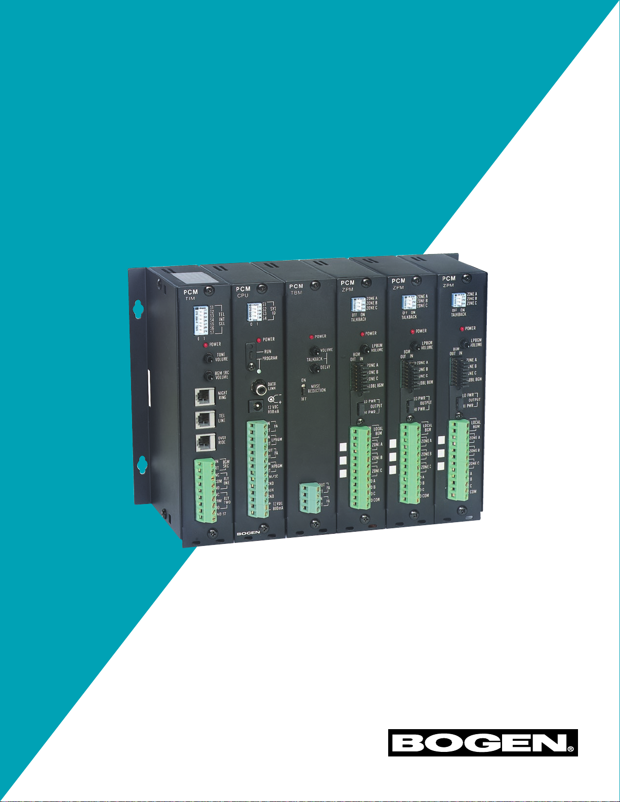
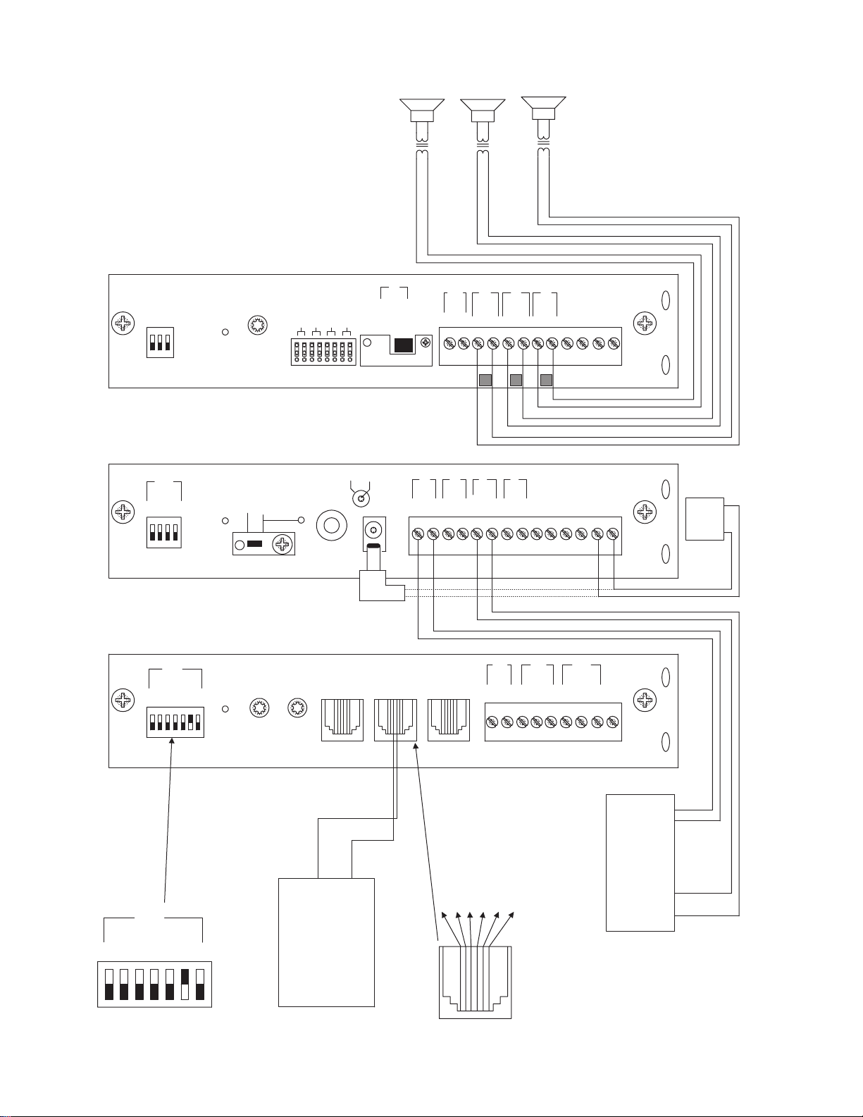
SETUP FOR CONFIGURATION 1: PAGE PORT CONTACT CLOSURE - 3-ZONE - ONE-WAY PAGING - SINGLE AMPLIFIER - 25/70V AC SPEAKERS

CONFIGURATION 1:
PAGE PORT CONTACT CLOSURE - 3-ZONE - ONE-WAY PAGING - SINGLE AMPLIFIER - 25/70V AC SPEAKERS
In this configuration, the PCM unit responds to a contact closure on pins 2 & 5 of the TEL LINE jack on the PCMTIM module shorting the
+5V source to its ground.When the closure is removed, the page ends.Audio is provided to the system through a separate pair of leads on
pins 3 & 4 of the TEL LINE jack on the PCMTIM module. Pins 1 & 6 are not used in this configuration.
Note:The audio pair (page port) must pass DTMF in order to select a zone.
The required setup includes PCMTIM - PCMCPU - PCMZPM - PCMPS2. Modules must be assembled, from left to right, in this order.
INSTALLATION:
STEP 1: Assembling Modules PCMTIM to PCMCPU and to PCMZPM (see Illustration on page 38)
• Plug the 6-pin power connector from the PCMCPU module to the PCMTIM module jack (J2). Be sure that the locking ridge faces head-
er wall. (Green wire to the top.)
• Plug the 26-pin ribbon cable from the PCMCPU module to the PCMTIM module 26-pin connector (J1). Be sure to align the polarizing
tab in slot. (Pin 1 red stripe to the top.)
• Place the modules together and dress the connector cables away from the sheet metal so they will not get pinched.
• Push the two units together while aligning the locking tabs in the PCMTIM module to the locking slots in the PCMCPU module. Slide
the two units until the faces of both units are even.
• Secure the two units together by tightening a screw into the screw clamp tab in the back of the PCMTIM.
• Follow the same steps to add the PCMZPM module.
Note: Do NOT connect the PCMPS2 (power supply) at this point.
STEP 2: Connecting Paging Port/Contact Closure from the Telephone System to the PCMTIM Module
• Take the page port audio pair from the telephone system and wire it to the RJ11 TEL-LINE jack to pins 3 & 4 (red and green); and the
contact closure pair to pins 2 & 5 (black and yellow).
• Use a 4- or 6-pin modular cord to connect the RJ11 to the TEL-LINE input on the PCMTIM module.
STEP 3: Switch Settings
• Set the TEL-INT-SEL DIP switches on the PCMTIM module for Page Port Contact Closure configuration: switches 2, 3 & 7 ON (to the
right) and switches 1, 4, 5 & 6 OFF (to the left).
• Set the SYS-ID DIP switches on the PCMCPU module to the OFF position (to the left).
• Set the RUN-PROGRAM switch on the PCMCPU module to the RUN mode (up).
• Set the Talk Back DIP switches on the PCMZPM module to the OFF position (to the left) for all zones.
• Set the OUTPUT switch on the PCMZPM module to the HI-PWR position (down).
STEP 4: Testing your System
• Connect power supply PCMPS2 to the PCMCPU module to either the power jack 12V DC input or wire it to the 12V DC screw ter-
minals observing polarity.
• At this point all the power LEDs should be lit on each module.
• Access the page port from the phone system and verify access tones (double beep) in handset.
• At this point, the system should be functioning properly.
• Disconnect Power Supply.
STEP 5: Connecting the Paging Amplifier
• Locate the terminals on the PCMCPU module labeled PA IN/RT and wire to the TIP and Ring (T & R) input on the Bogen paging amplifi-
er (either TPU-Series, GS-Series or Classic Series.)
• Locate the terminals on the PCMCPU module labeled PA OUT/RT and wire to COMMON and either the 25 or 70V output on the
paging amplifier.
STEP 6: Connecting 25/70V AC Speakers
• Locate the terminals on the PCMZPM module labeled ZONE A.These terminals have two connections marked + and -.Wire your
speakers for ZONE ONE to these terminals. Observe polarity (-) to common (+) to selected tap setting.
• Follow the same procedure for the terminals labeled ZONE B for ZONE TWO, and the terminals labeled ZONE C for ZONE THREE.
STEP 7: Testing your System
• Connect the power supply PCMPS2 to the PCMCPU module to either the power jack 12V DC input or wire it to the 12V DC screw
terminals, observing polarity.
• Connect the Bogen amplifier to the AC power outlet (120V AC, 60Hz).
• Set the volume on your Bogen amplifier to a 1/2 turn.
• Access the paging from the telephone system and listen (on the handset) for the confirmation tone (double beep).
• Dial 01 to access ZONE ONE and listen (on the handset and also to the speakers) for a pre-announce tone (single beep) followed by
your page (audio).
• Follow the same steps for ZONES TWO (02) and THREE (03).
• Set the Bogen amplifier to the desired volume level.
5

6
PCM
TIM
POWER
TONE
VOLUME
BGM SRC
VOLUME
GND ST
IN
RT
BGM
SRC
NIGHT
RING
TEL
LINE
OVER
RIDE
NC
COM
NO
NC
COM
NO
RLY
ONE
RLY
TWO
S1
S2
S3
S4
S5
S6
S7
TEL
INT
SEL
0 1
POWER
- 1.5A
OUT
RT
GND
AUX
GND
S1
S2
S3
S4
0 1
SYS
ID
RUN
PROGRAM
DATA
LINK
12 VDC
1.5A
-
IN
RT
RT
IN
RT
IN
EM/SC
+ 12VDC
BOGEN
PA
LPBGM
PA
HPBGM
+
POWER
RD COM
+
-
RD A
RD B
ZONE A
ZONE B
ZONE C
OFF ON
TALKBACK
RT
IN
RD C
LOCAL
BGM
ZONE A
+
-
ZONE B
+
-
ZONE C
LPBGM
VOLUME
LO PWR
HI PWR
OUTPUT
BGM
OUT IN
PCM
ZPM
PCM
CPU
PBX
PAGING
PORT
VOX
T
R
1 - Not used
2 - Not used
3 - Dry audio (R)
4 - Dry audio (T)
5 - Not used
6 - Not used
+
-
PCM PS2
RT
70V COM
BOGEN PAGING
AMPLIFIER
S1
S2
S3
S4
S5
S6
S7
TEL
INT
SEL
0 1
ZONE A
ZONE B
ZONE C
GLOBL BGM
ZONE C
ZONE B
ZONE A
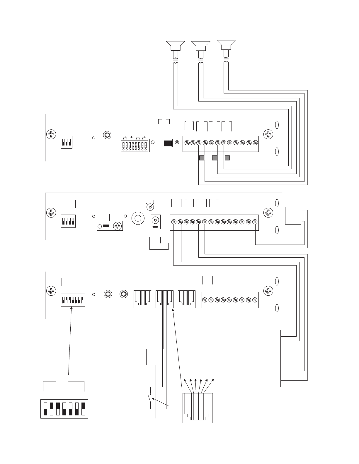
SETUP FOR CONFIGURATION 2: PAGE PORT VOX CIRCUIT - 3-ZONE - ONE-WAY PAGING - SINGLE AMPLIFIER - 25/70V AC SPEAKERS

CONFIGURATION 2:
PAGE PORT VOX CIRCUIT - 3-ZONE - ONE-WAY PAGING - SINGLE AMPLIFIER - 25/70V AC SPEAKERS
This configuration is for Page Ports without Contact Closures.A dry audio pair connected to pins 3 & 4 of the TEL LINE jack on the
PCMTIM module is used to detect audio and activate the system. Paging ends when the VOX timer or default timer times out. Pins 1,2,5 &
6 are not used in this configuration.
Note:The audio pair (page port) must pass DTMF in order to select a zone.
The required setup includes: PCMTIM - PCMCPU - PCMZPM - PCMPS2. Modules must be assembled, from left to right, in this order.
INSTALLATION:
STEP 1: Assembling Modules PCMTIM to PCMCPU and to PCMZPM
• Follow the same procedure described previously on page 5, step 1.
Note: Do NOT connect the PCMPS2 (power supply) at this point.
STEP 2: Connecting Paging Port/VOX from the Telephone System to the PCMTIM Module
• Take the page port (VOX) audio pair from the telephone system and wire it to the RJ11 TEL-LINE jack in the PCMTIM module to pins
3 & 4 (red and green).
• Use a 4- or 6-pin modular cord to connect the RJ11 to the TEL-LINE input on the PCMTIM module.
STEP 3: Switch Settings
• Set the TEL-INT-SEL DIP switches on the PCMTIM module for Page Port VOX configuration: switches 1 & 7 ON (to the right) and
switches 2, 3, 4, 5 & 6 OFF (to the left).
• Set the SYS-ID DIP switches on the PCMCPU module to the OFF position (to the left).
• Set the RUN-PROGRAM switch on the PCMCPU module to the RUN mode (up).
• Set the Talk Back DIP switches on the PCMZPM module to the OFF position (to the left) for all zones.
• Set the OUTPUT switch on the PCMZPM module to the HI-PWR position (down).
STEP 4: Testing your System
• Follow the same procedure described previously on page 5, step 4.
STEP 5: Connecting the Paging Amplifier
• Follow the same procedure described previously on page 5, step 5.
STEP 6: Connecting 25/70V AC Speakers
• Follow the same procedure described previously on page 5, step 6.
STEP 7: Testing your System
• Follow the same procedure described previously on page 5, step 7.
7
8
PCM
TIM
POWER
TONE
VOLUME
BGM SRC
VOLUME
GND ST
IN
RT
BGM
SRC
NIGHT
RING
TEL
LINE
OVER
RIDE
NC
COM
NO
NC
COM
NO
RLY
ONE
RLY
TWO
S1
S2
S3
S4
S5
S6
S7
TEL
INT
SEL
0 1
POWER
- 1.5A
OUT
RT
GND
AUX
GND
S1
S2
S3
S4
0 1
SYS
ID
RUN
PROGRAM
DATA
LINK
12 VDC
1.5A
-
IN
RT
RT
IN
RT
IN
EM/SC
+ 12VDC
BOGEN
PA
LPBGM
PA
HPBGM
+
POWER
RD COM
+
-
RD A
RD B
ZONE A
ZONE B
ZONE C
OFF ON
TALKBACK
RT
IN
RD C
LOCAL
BGM
ZONE A
+
-
ZONE B
+
-
ZONE C
LPBGM
VOLUME
LO PWR
HI PWR
OUTPUT
BGM
OUT IN
PCM
ZPM
PCM
CPU
PBX
LOOP START
TRUNK PORT
T
R
1 - Not used
2 - Not used
3 - Ring (Negative)
4 - Tip (Positive)
5 - Not used
6 - Not used
+
-
PCM PS2
RT
70V COM
BOGEN PAGING
AMPLIFIER
S1
S2
S3
S4
S5
S6
S7
TEL
INT
SEL
0 1
ZONE A
ZONE B
ZONE C
GLOBL BGM
ZONE C
ZONE B
ZONE A
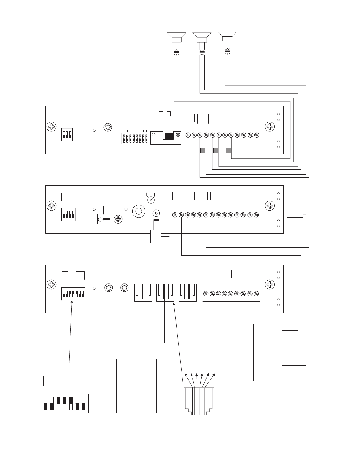
SETUP FOR CONFIGURATION 3: LOOP START TRUNK - 3-ZONE - ONE-WAY PAGING - SINGLE AMPLIFIER - 25/70V AC SPEAKERS

CONFIGURATION 3:
LOOP START TRUNK - 3-ZONE - ONE-WAY PAGING - SINGLE AMPLIFIER - 25/70V AC SPEAKERS
In this configuration, the PCM unit supplies a 48V talk battery and loop current detection from pins 3 & 4 of the TEL LINE jack on the
PCMTIM module to the loop start trunk in the telephone system.There are two modes of operation for loop start trunk.
(1) When the unit detects a loop resistance between TIP and RING, it activates.When the loop opens, the page ends. Pins 1, 2, 5 & 6 are not
used in this configuration. Note: Default and VOX timers are not used in this mode.
(2) The unit will operate as in mode one, except it will also provide a one-second hook flash after the expiration of the VOX and/or Default
timers. Operation in this mode will enable the unit to automatically disconnect itself from the loop start trunk of the PBX.This will prevent
the paging system from being locked up indefinitely in the event a telephone is accidentally left off hook after a page has been completed.The
feature codes are 014 to inhibit and 015 to enable this feature. The default feature code is 014 (OFF).
The required setup includes PCMTIM - PCMCPU - PCMZPM - PCMPS2. Modules must be assembled, from left to right, in this order.
INSTALLATION:
STEP 1: Assembling Modules PCMTIM to PCMCPU and to PCMZPM
• Follow the same procedure described previously on page 5, step 1.
Note: Do NOT connect the PCMPS2 (power supply) at this point.
STEP 2: Connecting Loop Start Trunk from the Telephone System to the PCMTIM Module
• Take the loop start trunk pair from the telephone system and wire it to the RJ11 TEL-LINE jack in the PCMTIM module to pins 3 and 4
(red and green).
• Use a 4 or 6-pin modular cord to connect the RJ11 to the TEL-LINE input on the PCMTIM module.
STEP 3: Switch Settings
• Set the TEL-INT-SEL DIP switches on the PCMTIM module for Loop Start Trunk configuration: switches 3, 4 & 5 ON (to the right) and
switches 1, 2, 6 & 7 OFF (to the left).
• Set the SYS-ID DIP switches on the PCMCPU module to the OFF position (to the left).
• Set the RUN-PROGRAM switch on the PCMCPU module to the RUN mode (up).
• Set the Talk Back DIP switches on the PCMZPM module to the OFF position (to the left) for all zones.
• Set the OUTPUT switch on the PCMZPM module to the HI-PWR position (down).
STEP 4: Testing your System
• Connect power supply PCMPS2 to the PCMCPU module to either the power jack 12V DC input or wire it to the 12V DC screw ter-
minals observing polarity.
• Power LEDs should be lit on each module.
• Access the Loop Start Trunk from the phone system and verify access tones (double beep).
• At this point, the system should be functioning properly.
• Disconnect Power Supply.
STEP 5: Connecting the Paging Amplifier
• Follow the same procedure described previously on page 5, step 5.
STEP 6: Connecting 25/70V AC Speakers
• Follow the same procedure described previously on page 5, step 6.
STEP 7: Testing your System
• Connect the power supply PCMPS2 to the PCMCPU module to either the power jack 12V DC input or wire it to the 12V DC screw
terminals observing polarity.
• Connect the Bogen amplifier to the AC power outlet (120V AC 60Hz).
• Set the volume on your Bogen amplifier to a 1/2 turn.
• Access the Loop Start Trunk from the telephone system and listen (on the handset) for the confirmation tone (double beep).
• Dial 01 to access ZONE ONE and listen (on the handset and also to the speakers) for a pre-announce tone (single beep) followed by
your page (audio)
• Follow the same steps for ZONES TWO (02) and THREE (03).
• Set the Bogen amplifier to the desired volume level.
9
10
PCM
TIM
POWER
TONE
VOLUME
BGM SRC
VOLUME
GND ST
IN
RT
BGM
SRC
NIGHT
RING
TEL
LINE
OVER
RIDE
NC
COM
NO
NC
COM
NO
RLY
ONE
RLY
TWO
S1
S2
S3
S4
S5
S6
S7
TEL
INT
SEL
0 1
POWER
- 1.5A
OUT
RT
GND
AUX
GND
S1
S2
S3
S4
0 1
SYS
ID
RUN
PROGRAM
DATA
LINK
12 VDC
1.5A
-
IN
RT
RT
IN
RT
IN
EM/SC
+ 12VDC
BOGEN
PA
LPBGM
PA
HPBGM
+
POWER
RD COM
+
-
RD A
RD B
ZONE A
ZONE B
ZONE C
OFF ON
TALKBACK
RT
IN
RD C
LOCAL
BGM
ZONE A
+
-
ZONE B
+
-
ZONE C
LPBGM
VOLUME
LO PWR
HI PWR
OUTPUT
BGM
OUT IN
PCM
ZPM
PCM
CPU
PBX
GROUND
START
TRUNK
T
R
1 - Not used
2 - Not used
3 - Ring (Negative)
4 - Tip (Positive)
5 - Not used
6 - Not used
+
-
PCM PS2
RT
70V COM
BOGEN PAGING
AMPLIFIER
S1
S2
S3
S4
S5
S6
S7
TEL
INT
SEL
0 1
PBX Ground
ZONE A
ZONE B
ZONE C
GLOBL BGM
ZONE C
ZONE B
ZONE A
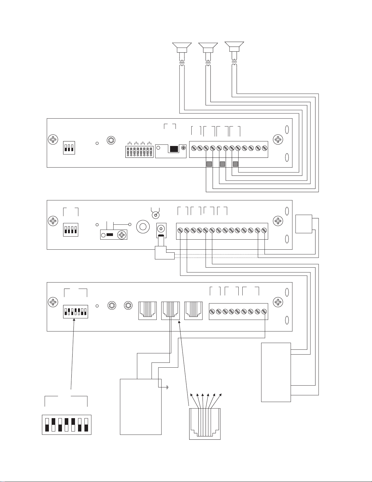
SETUP FOR CONFIGURATION 4: GROUND START TRUNK - 3-ZONE - ONE-WAY PAGING - SINGLE AMPLIFIER - 25/70V AC SPEAKERS

CONFIGURATION 4:
GROUND START TRUNK - 3-ZONE - ONE-WAY PAGING - SINGLE AMPLIFIER - 25/70V AC SPEAKERS
In this configuration, the PCM unit supplies a 48V talk battery and loop current detection from pins 3 & 4 of the TEL LINE jack on the
PCMTIM module to the ground start trunk in the telephone system.There are two modes of operation for ground start trunk.
(1) When the ground start trunk grounds Ring, the unit responds by closing the connection to Tip, which completes the access procedure.
When the loop is opened, the page ends. Pins 1, 2, 5 & 6 are not used in this configuration. Note: Default and VOX timers are not used
in this mode.
(2) The unit will operate as in mode one, except it will also provide a one-second hook flash after the expiration of the VOX and/or Default
timers. Operation in this mode will enable the unit to automatically disconnect itself from the ground start trunk of the PBX.This will pre-
vent the paging system from being locked up indefinitely in the event a telephone is accidentally left off hook after a page has been complet-
ed.The feature codes are 014 to inhibit and 015 to enable this feature.The default feature code is 014 (OFF).
The required setup includes PCMTIM - PCMCPU - PCMZPM - PCMPS2. Modules must be assembled, from left to right, in this order.
INSTALLATION:
STEP 1: Assembling Modules PCMTIM to PCMCPU and to PCMZPM
• Follow the same procedure described previously on page 5, step 1.
Note: Do NOT connect the PCMPS2 (power supply) at this point.
STEP 2: Connecting the Ground Start Trunk from the Telephone System to the PCMTIM Module
• Take the ground start trunk pair from the telephone system and wire it to the RJ11 TEL-LINE jack in the PCMTIM module to pins 3 and
4 (red and green).
• Use a 4 or 6-pin modular cord to connect the RJ11 to the TEL-LINE input on the PCMTIM module.
• Use a 24-gauge solid wire to connect the GND ST terminal on the PCMTIM module to the PBX ground.This is typically the AC ground
for the PBX system.
STEP 3: Switch Settings
• Set the TEL-INT-SEL DIP switches on the PCMTIM module for Ground Start Trunk configuration: switches 2, 4 & 5 ON (to the right)
and switches 1, 3, 6 & 7 OFF (to the left).
• Set the SYS-ID DIP switches on the PCMCPU module to the OFF position (to the left).
• Set the RUN-PROGRAM switch on the PCMCPU module to the RUN mode (up).
• Set the Talk Back DIP switches on the PCMZPM module to the OFF position (to the left) for all zones.
• Set the OUTPUT switch on the PCMZPM module to the HI-PWR position (down).
STEP 4: Testing your System
• Connect power supply PCMPS2 to the PCMCPU module to either the power jack 12V DC input or wire it to the 12V DC screw ter-
minals observing polarity.
• At this point all the power LEDs should be lit on each module.
• Access the Ground Start Trunk from the phone system and verify access tones (double beep).
• At this point, the system should be functioning properly.
• Disconnect Power Supply.
STEP 5: Connecting the Paging Amplifier
• Follow the same procedure described previously on page 5, step 5.
STEP 6: Connecting 25/70V AC Speakers
• Follow the same procedure described previously on page 5, step 6.
STEP 7: Testing your System
• Connect the power supply PCMPS2 to the PCMCPU module to either the power jack 12V DC input or wire it to the 12V DC screw
terminals observing polarity.
• Connect the Bogen amplifier to the AC power outlet (120V AC 60Hz).
• Set the volume on your Bogen amplifier to a 1/2 turn.
• Access the Ground Start Trunk from the telephone system and listen (on the handset) for the confirmation tone (double beep).
• Dial 01 to access ZONE ONE and listen (on the handset and also to the speakers) for a pre-announce tone (single beep) followed by
your page (audio).
• Follow the same steps for ZONES TWO (02) and THREE (03).
• Set the Bogen amplifier to the desired volume level.
11
12
PCM
TIM
POWER
TONE
VOLUME
BGM SRC
VOLUME
GND ST
IN
RT
BGM
SRC
NIGHT
RING
TEL
LINE
OVER
RIDE
NC
COM
NO
NC
COM
NO
RLY
ONE
RLY
TWO
S1
S2
S3
S4
S5
S6
S7
TEL
INT
SEL
0 1
POWER
- 1.5A
OUT
RT
GND
AUX
GND
S1
S2
S3
S4
0 1
SYS
ID
RUN
PROGRAM
DATA
LINK
12 VDC
1.5A
-
IN
RT
RT
IN
RT
IN
EM/SC
+ 12VDC
BOGEN
PA
LPBGM
PA
HPBGM
+
POWER
RD COM
+
-
RD A
RD B
ZONE A
ZONE B
ZONE C
OFF ON
TALKBACK
RT
IN
RD C
LOCAL
BGM
ZONE A
+
-
ZONE B
+
-
ZONE C
LPBGM
VOLUME
LO PWR
HI PWR
OUTPUT
BGM
OUT IN
PCM
ZPM
PCM
CPU
PBX
STATION
ACCESS
CENTREX
T
R
1 - Not used
2 - Not used
3 - Ring (Negative)
4 - Tip (Positive)
5 - Not used
6 - Not used
+
-
PCM PS2
RT
70V COM
BOGEN PAGING
AMPLIFIER
S1
S2
S3
S4
S5
S6
S7
TEL
INT
SEL
0 1
ZONE A
ZONE B
ZONE C
GLOBL BGM
ZONE C
ZONE B
ZONE A
SETUP FOR CONFIGURATION 5: STATION LEVEL/CENTREX - 3-ZONE - ONE-WAY PAGING - SINGLE AMPLIFIER - 25/70V AC SPEAKERS

CONFIGURATION 5:
STATION LEVEL/CENTREX - 3-ZONE - ONE-WAY PAGING - SINGLE AMPLIFIER - 25/70V AC SPEAKERS
In this configuration, the PCM unit responds to a 90V AC 20Hz ringing signal in pins 3 & 4 of the TEL LINE jack on the PCMTIM module and
answers after the first full ring.As soon as it answers, the default timer is started.The default timer determines the maximum length of any
page.When a paging zone is selected, the VOX timer (if enabled) is started.This VOX timer repeatedly resets as long as audio is detected on
the line. If no audio is detected within the VOX time period, the page will end. If audio continues to be detected, the default timer will con-
trol the page length. Pins 1, 2, 5 & 6 are not used in this configuration.
Note: In this configuration, the unit will also respond to CPC pulses (interruption of loop current) disconnecting the line.
The required setup includes PCMTIM -PCMCPU - PCMZPM - PCMPS2. Modules must be assembled, from left to right, in this order.
INSTALLATION:
STEP 1: Assembling Modules PCMTIM to PCMCPU and to PCMZPM
• Follow the same procedure described previously on page 5, step 1.
Note: Do NOT connect the PCMPS2 (power supply) at this point.
STEP 2: Connecting the Station Level/Centrex from the Telephone System to the PCMTIM Module
• Take the Station Level/Centrex pair from the telephone system and wire it to the RJ11 TEL-LINE jack in the PCMTIM module to pins 3
and 4 (red and green).
• Use a 4 or 6-pin modular cord to connect the RJ11 to the TEL-LINE input on the PCMTIM module.
STEP 3: Switch Settings
• Set the TEL-INT-SEL DIP switches on the PCMTIM module for Station Level/Centrex configuration: switch 6 ON (to the right) and
switches 1, 2, 3, 4, 5 & 7 OFF (to the left).
• Set the SYS-ID DIP switches on the PCMCPU module to the OFF position (to the left).
• Set the RUN-PROGRAM switch on the PCMCPU module to the RUN mode (up).
• Set the Talk Back DIP switches on the PCMZPM module to the OFF position (to the left) for all zones.
• Set the OUTPUT switch on the PCMZPM module to the HI-PWR position (down).
STEP 4: Testing your System
• Connect power supply PCMPS2 to the PCMCPU module to either the power jack 12V DC input or wire it to the 12V DC screw ter-
minals observing polarity.
• At this point all the power LEDs should be lit on each module.
• Access the Station Level/Centrex line from the phone system and verify access tones (double beep).
• At this point, the system should be functioning properly.
• Disconnect Power Supply.
STEP 5: Connecting the Paging Amplifier
• Follow the same procedure described previously on page 5, step 5.
STEP 6: Connecting 25/70V AC Speakers
• Follow the same procedure described previously on page 5, step 6.
STEP 7: Testing your System
• Connect the power supply PCMPS2 to the PCMCPU module to either the power jack 12V DC input or wire it to the 12V DC screw
terminals observing polarity.
• Connect the Bogen amplifier to the AC power outlet (120V AC 60Hz).
• Set the volume on your Bogen amplifier to a 1/2 turn.
• Access the Station Level/Centrex port from the telephone system and listen (on the handset) for the confirmation tone (double beep).
• Dial 01 to access zone ONE and listen (on the handset and also to the speakers) for a pre-announce tone (single beep) followed by
your page (audio).
• Follow the same steps for ZONES TWO (02) and THREE (03).
• Set the Bogen amplifier to the desired volume level.
13
 Loading...