


Owners Manual Manuel d’utilisation
U.S. Patent Number: 6,470,877
Brevet U.S. nº 6,470,877
While information in this manual is based on the latest information available at the time of publication, we reserve the right to change it at any time, without notice.
Bien que les informations contenues dans ce manuel constituent les informations disponibles les plus récentes au moment de sa publication, nous nous réservons le droit d’en modifier le contenu à tout moment et sans préavis.
Model No. / Modèle nº
200605C
WARNING
FOR YOUR SAFETY
For Outdoor Use Only
(Outside any enclosure)
MISE EN GARDE
POUR VOTRE SÉCURITÉ:
Pour usage à l’extérieur seulement
(hors de tout espace clos)
WARNING
FOR YOUR SAFETY
Improper installation, adjustment, alteration, service or maintenance can cause injury or property
damage. Read the installation, operation and maintenance instructions thoroughly before installing or servicing this equipment.
MISE EN GARDE
POUR VOTRE SÉCURITÉ:
Toute installation défectueuse ou modification incorrecte ainsi que tout mauvais réglage ou entretien incorrect risque d’entraîner des blessures ou des dégâts matériels. Lire complètement les instructions d’installation, d’utilisation et d’entretien avant de procéder à la maintenance de l’appareil ou à son entretien.
Contact 1.800.762.1142 for assistance. Do not return to place of purchase.
WARNING
FOR YOUR SAFETY
For Outdoor Use Only (Outside any enclosure)
WARNING
FOR YOUR SAFETY If you smell gas:
1.Shut off gas to the appliance.
2.Extinguish any open flame.
3.If odor continues, immediately call your gas supplier.
WARNING
FOR YOUR SAFETY
1.Gas leaks may cause a fire or explosion which can cause serious bodily injury or death, or damage to property.
2.You must follow all leak checking procedures as outlined in step 12 before operating this unit.
3.Never use an open flame to check for leaks.
WARNING
FOR YOUR SAFETY
Do not store or use gasoline or other flammable vapors or liquids in the vicinity of this or any other appliance.
WARNING
FOR YOUR SAFETY
Improper installation, adjustment, alteration, service or maintenance can cause injury or property damage. Read the installation, operation and maintenance instructions thoroughly before installing or servicing this equipment
WARNING
California Proposition 65:
Chemicals known to the state of California to cause cancer, birth defects, or other reproductive harm are created by the combustion of propane.
WARNING
FOR YOUR SAFETY
•Purchaser assumes all risk in the assembly and operation of this unit. Failure to follow this manual’s WARNINGs and instructions can result in severe personal injury, death or property damage.
•Do not use in an explosive atmosphere. Keep heater away from areas where flammable liquids, gasoline, vapors, or explosives are stored or used.
|
Owner’s manual: model 200605C outdoor patio heater |
Contact 1.800.762.1142 for assistance. Do not return to place of purchase.
Table of Contents
Safety First! |
. . . . . . . . . . . . . . . . . . . . . . . . . . . . . . . . . . . . . . . . . . . . . . . . . . . . |
3 |
Component Listing & Hardware . . . . . . . . . . . . . . . . . . . . . . . . . . . . . . . . . . . . . |
.5 |
|
General Components & Features . . . . . . . . . . . . . . . . . . . . . . . . . . . . . . . . . . . . |
6 |
|
Assembly Instructions |
|
|
Additional Requirements . . . . . . . . . . . . . . . . . . . . . . . . . . . . . . . . . . . . . . |
6 |
|
Step 1 |
Attach Legs to Base . . . . . . . . . . . . . . . . . . . . . . . . . . . . . . . . . . . . |
6 |
Step 2 |
Attach Platform to Legs . . . . . . . . . . . . . . . . . . . . . . . . . . . . . . . . . |
.7 |
Step 3 |
Attach Weight Plate to Base . . . . . . . . . . . . . . . . . . . . . . . . . . . . . |
.7 |
Step 4 |
Insert Gas Line Through Platform / Attach Shroud Cover . . . . . . |
.8 |
Step 5 |
Attach Engine to Post . . . . . . . . . . . . . . . . . . . . . . . . . . . . . . . . . . |
.8 |
Step 6 |
Attach Engine/Post to Platform . . . . . . . . . . . . . . . . . . . . . . . . . . . |
9 |
Step 7 |
Connect Gas Line to Engine . . . . . . . . . . . . . . . . . . . . . . . . . . . . . |
.9 |
Step 8 Assemble dome . . . . . . . . . . . . . . . . . . . . . . . . . . . . . . . . . . . . . . |
10 |
|
Step 9 |
Attach dome to emitter . . . . . . . . . . . . . . . . . . . . . . . . . . . . . . . . |
10 |
Step 10 Secure Gas Line . . . . . . . . . . . . . . . . . . . . . . . . . . . . . . . . . . . . |
11 |
|
Step 11 Connect Gas Line To Tank . . . . . . . . . . . . . . . . . . . . . . . . . . . . |
11 |
|
Step 12 Check for Leaks . . . . . . . . . . . . . . . . . . . . . . . . . . . . . . . . . . . . |
12 |
|
Step 13 Replace Engine Access Panel . . . . . . . . . . . . . . . . . . . . . . . . . . . |
13 |
|
Step 14 Install Igniter Battery (Electronic Ignition Models Only .. .. .. .. .. .. .. |
13 |
|
Operation |
|
|
Before Turning Gas Supply ON . . . . . . . . . . . . . . . . . . . . . . . . . . . . . . . . |
14 |
|
Before Lighting . . . . . . . . . . . . . . . . . . . . . . . . . . . . . . . . . . . . . . . . . . . . |
14 |
|
Lighting . . . . . . . . . . . . . . . . . . . . . . . . . . . . . . . . . . . . . . . . . . . . . . . . . . |
14 |
|
Re-Lighting . . . . . . . . . . . . . . . . . . . . . . . . . . . . . . . . . . . . . . . . . . . . . . . |
15 |
|
Shutdown . . . . . . . . . . . . . . . . . . . . . . . . . . . . . . . . . . . . . . . . . . . . . . . . . |
15 |
|
Operation Checklist . . . . . . . . . . . . . . . . . . . . . . . . . . . . . . . . . . . . . . . . . |
16 |
|
Troubleshooting . . . . . . . . . . . . . . . . . . . . . . . . . . . . . . . . . . . . . . . . . . . . . . . . 17
Maintenance . . . . . . . . . . . . . . . . . . . . . . . . . . . . . . . . . . . . . . . . . . . . . . . . . . . 18
Storage . . . . . . . . . . . . . . . . . . . . . . . . . . . . . . . . . . . . . . . . . . . . . . . . . . . . . . . 19
Service . . . . . . . . . . . . . . . . . . . . . . . . . . . . . . . . . . . . . . . . . . . . . . . . . . . . . . . |
19 |
Product Registration . . . . . . . . . . . . . . . . . . . . . . . . . . . . . . . . . . . . . . . . . . . . |
19 |
Warranty . . . . . . . . . . . . . . . . . . . . . . . . . . . . . . . . . . . . . . . . . . . . . . . . . . . . . . 20
Specifications . . . . . . . . . . . . . . . . . . . . . . . . . . . . . . . . . . . . . . . . . . . . . . . . . . 21
The use and installation of this product must conform to local codes.. In absence of local codes, us the National Fuel and Gas Code, ANSI Z223, 1/NFPA 54, Storage and Handling of Liquid Petroleum Gases, ANSI/NFPA 58 or CSA B149.1 , Natural Gas and Propane Installation Code..
Save these instructions for future reference.. If you are assembling this unit for someone else, give this manual to him or her to save for future reference..
Owner’s manual: model 200605C outdoor patio heater
Contact 1.800.762.1142 for assistance. Do not return to place of purchase.
Safety First!
Read and become familiar with this entire manual, especially the following precautions..
If you are unsure of anything in these instructions, STOP and contact
1..800..762.11 42 for assistance..
Before you do anything else, read and understand all precautions in Safety First!
WARNING
FOR YOUR SAFETY
•Purchaser assumes all risk in the assembly and operation of this unit. Failure to follow this manual’s WARNINGs and instructions can result in severe personal injury, death or property damage.
•Do not use in an explosive atmosphere. Keep heater away from areas where flammable liquids, gasoline, vapors, or explosives are stored or used.
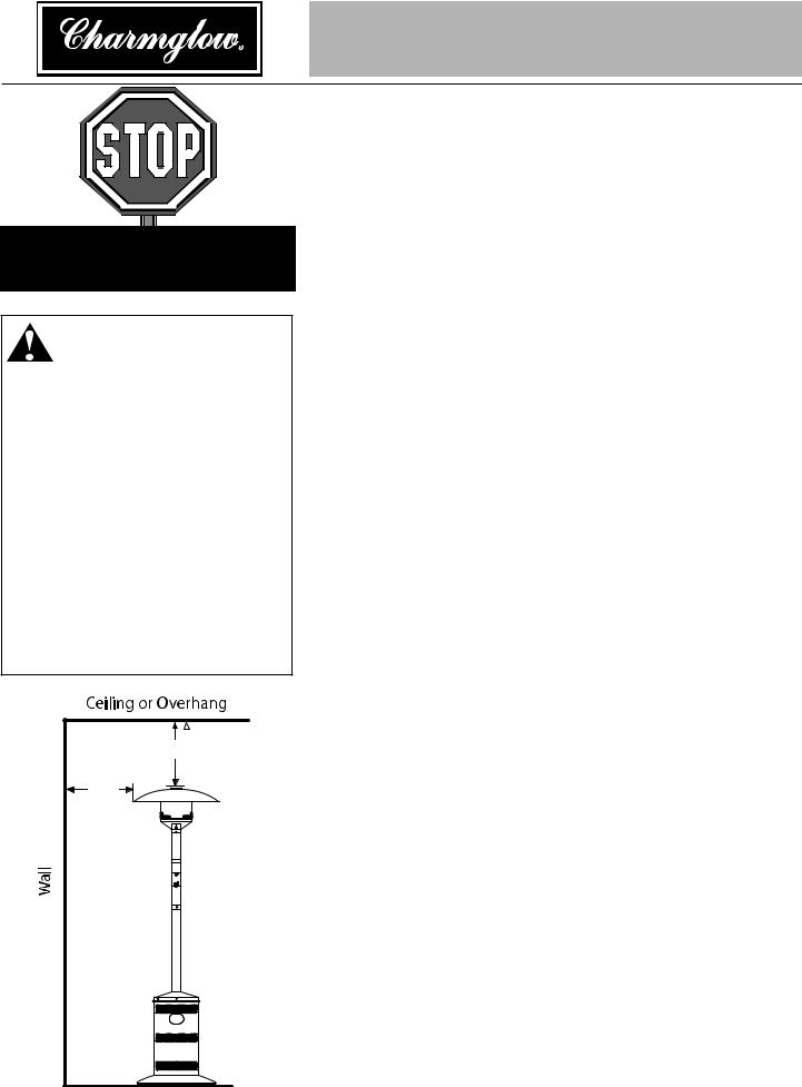
Caution: This appliance is for outdoor use only (outside any enclosure). Always make sure there is fresh air ventilation.
•Always maintain at least 36” clearance (top) and 24” clearance (side) from combustible materials..
•Always place heater on a hard and level surface..
•Do not use if the wind velocity is greater than 10 miles per hour..
•Unit will operate at reduced efficiency below 40ºF (5ºC)..
•Keep sprinklers and other water sources away from burner and controls..
•Always use extreme caution when near heater. Alert both children and adults to the hazards of high temperatures, especially to avoid burns or clothing catching fire.
•Young children and pets should be carefully supervised when they are in the area of heater.
•Do not hang clothing or other flammable materials either on or near heater.
•Any guard or other protective device removed for servicing the heater must be replaced prior to operating the heater.
•Certain materials or items, when stored under heater, will be subjected to radiant heat and could be seriously damaged..
•Do not alter heater in any manner..
36” |
24” |
•The pressure regulator and hose assembly supplied with the appliance must be used and replacements must be those specified by the manufacturer..
•Inspect heater before each use.. If a damaged part is detected, do not operate until an original equipment replacement part has been properly installed.. Use of unauthorized parts will void warranty and create an unsafe condition..
•Do not attempt to use this appliance without a functional factorysupplied gas regulator in place.. If regulator becomes damaged, use only a factory-supplied replacement..
•Prior to operating heater, replace any guards or protective devices removed for servicing..
•During operation, do not touch burner assembly.. The surface of heater’s emitter can reach temperatures approaching 1600ºF..
•After shutdown, do not touch burner assembly until heater has cooled (approximately 45 minutes after use)..
Notice: This product should not be used with any fuel other than liquid propane.. Use of other fuels will detract from heaters performance and will void your warranty..
Owner’s manual: model 200605C outdoor patio heater
Contact 1.800.762.1142 for assistance. Do not return to place of purchase.
Caution: Liquid propane (LP) gas is flammable and hazardous if handled improperly. Become aware of the characteristics before using any LP product.
•LP Characteristics – Flammable, explosive under pressure, heavier than air - settles in pools in low areas..
•In its natural state, propane has no odor.. For your safety, an odorant is added that smells like rotten cabbage..
•Contact with LP can cause freeze burns to skin..
•This heater is shipped from the factory for LP gas use only..
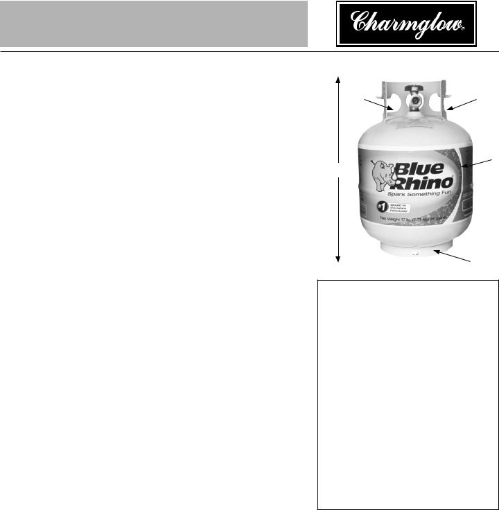
•Use only Department of Transportation (DOT) approved “20 lb..” LP gas tanks (same as those commonly used on gas grills) with Acme / Type 1 / QCC safety valves.. These valves can be quickly identified because they have external and internal threads..
•Never use an LP tank with a damaged body, valve, collar, or footring..
•Dented or rusted LP tanks may be hazardous and should be checked by your LP gas supplier..
•The tank supply system must be arranged for vapor withdrawl..
•The tank used must include a collar to protect the tank valve..
•When heater is not in use, turn LP tank OFF..
•Always perform a leak test on gas connections whenever a tank is connected.. Never use a flame to test for leaks.. Do not smoke while performing a leak test..
Caution: It is essential to keep the heater’s valve compartment, burners, and circulating air passages clean.
•Spiders and insects can create a dangerous condition that may damage heater or make it unsafe.. Keep burner area clean of all spiders, webs, or insects..
•Inspect heater before each use..
•Have heater inspected annually and repairs should be made by a qualified service person.
•Check heater immediately if any of the following conditions exist:
•The smell of gas in conjunction with extreme yellow tipping of burner flames..
•Heater does not reach proper temperature..
Note: At temperatures less than 40ºF, heat output will be reduced..
•Heater’s glow is excessively uneven
•Burner makes popping noises during use..
Note: A slight pop is normal when burner is extinguished..
•Carbon deposits may create a fire hazard.. Keep dome and emitter clean at all times..
•Do not clean heater with combustible or corrosive cleaners.. Use warm, soapy water..
•Do not paint engine, engine access panel or dome..
“20 lb.” LP Tank
Valve |
Collar |
Body
18”-19”
Foot
FOR YOUR SAFETY:
Beware of Spiders
Spiders or small insects can get into the burner tube or other openings of your heater, and spin webs or build nests. These obstructions can lead to gas flow problems. It is important to make frequent inspections of
these areas and clean them when necessary.
Before operating your heater for the first time, be sure to check for obstructions that may have occurred during shipment.
Need a tank or gas?
Try Blue Rhino tank exchange service.. It’s easy, fast, safe, and available at tens of thousands of conveniently located retail outlets nationwide.. You can purchase a new full tank or exchange your empty for a precision filled one..
For your nearest Blue Rhino retailer visit www.bluerhino.com.
Owner’s manual: model 200605C outdoor patio heater

Contact 1.800.762.1142 for assistance. Do not return to place of purchase.
Components |
Part |
Re-order |
|
|
|||
|
Name |
Number |
|
|
|
|
|
Finial . . . . . . . . . . .56-01-103
 Dome Cap . . . . . .56-01-104
 Dome Nut . . . . . . .56-01-208
Dome Plate . . . . . .56-01-105
 Dome Panel (3) . . .56-01-107
 Dome Rib (3) . . . . .56-01-109
Bottom Plate . . . .56-01-111
Dome Bolt . . . . . .56-01-212
Emitter . . . . . . . . .56-01-118
Pilot Assembly . . .56-01-127
Injector . . . . . . . . .56-01-125
Knob . . . . . . . . . . .56-01-156
Access Panel
Assembly . . . . . . .56-01-140
Impulse Ignitor . . .56-01-142
Valve . . . . . . . . . . .56-01-304
Valve Housing
Assembly . . . . . . .56-01-146
Pole . . . . . . . . . . .56-01-158
Shroud . . . . . . . . .56-01-164
Platform . . . . . . . .56-01-165
 Gas Line/ Regulator
Assembly . . . . . . .56-01-188
Legs (3) . . . . . . . . .56-01-193
 Base . . . . . . . . . . .56-01-329
 Weight Plate . . . . .56-01-198
Hardware
|
|
|
|
|
|
|
|
|
|
|
|
|
|
|
|
|
|
|
Used in |
Picture |
Qty |
|
Description |
Step(s) |
|||||||||||||||
|
|
Carriage Bolt |
3 |
||||||||||||||||
|
3/8-16 x 3-3/4” Zinc Plated Bolt |
||||||||||||||||||
|
|
56-01-199 |
|
|
|
|
|
|
|||||||||||
|
|
|
|
|
|
|
|
|
|
|
|
|
|
|
|
|
|
|
|
|
2 |
|
|
|
|
|
|
Bolt |
& 2 |
||||||||||
|
|
/4-20 x 3/4” Nickel |
|
||||||||||||||||
|
|
Plated Hex Head Bolt |
|
||||||||||||||||
|
|
56-01-200 |
|
|
|
|
|
|
|||||||||||
|
|
|
Large Screw |
2 |
|||||||||||||||
|
|
/4-20 x 1” Nickle Plated |
|||||||||||||||||
|
|
Philips Head Screw |
|
||||||||||||||||
|
|
56-01-202 |
|
|
|
|
|
|
|||||||||||
|
4 |
|
Small Screw |
5 |
|||||||||||||||
|
|
/4-20 x 3/8”Stainless Steel |
|||||||||||||||||
|
|
Philips Truss Head Screw |
|||||||||||||||||
|
|
56-01-2327 |
|
|
|
|
|||||||||||||
|
3 |
|
Dome Screw |
8 |
|||||||||||||||
|
|
5/32-32 x 1/4” Stainless Steel |
|||||||||||||||||
|
|
Round Head Screw |
|
||||||||||||||||
|
|
56-01-205 |
|
|
|
|
|
|
|||||||||||
|
2 |
Small Lockwasher |
1 & 2 |
||||||||||||||||
|
|
M6 Nickel plated Lockwasher |
|||||||||||||||||
|
|
56-01-328 |
|
|
|
|
|
|
|||||||||||
|
|
Large Lockwasher |
3 |
||||||||||||||||
|
|
M10 Nickel Plated |
|
||||||||||||||||
|
|
56-01-207 |
|
|
|
|
|
|
|||||||||||
|
|
|
|
|
Large Nut |
3 |
|||||||||||||
|
|
3/8-16 Nickel Plated Hex Nut |
|||||||||||||||||
|
|
56-01-330 |
|
|
|
|
|
|
|||||||||||
|
|
|
Medium Nut |
8 |
|||||||||||||||
|
|
3/8-16 Stainless Steel Hex Nut |
|||||||||||||||||
|
|
56-01-208 |
|
|
|
|
|
|
|||||||||||
|
5 |
|
|
|
Small Nut |
1, 2 & 9 |
|||||||||||||
|
|
/4-20 Nickel Plated Hex Nut |
|||||||||||||||||
|
|
56-01-209 |
|
|
|
|
|
|
|||||||||||
|
|
Gas Line Clip |
2 |
||||||||||||||||
|
|
56-01-213 |
|
|
|
|
|
|
|||||||||||
|
|
Allen Wrench |
6 |
||||||||||||||||
|
|
56-01-215 |
|
|
|
|
|
|
|||||||||||
Owner’s manual: model 200605C outdoor patio heater
Contact 1.800.762.1142 for assistance.
Do not return to place of purchase.
Assembly Instructions
General Components & Features
Familiarize yourself with all components before proceeding.. Refer to page 5 for hardware and components, and page 21 for specifications..
Do NOT attempt assembly unless all components are available.. If you believe a component is missing or damaged, contact 1..800..762.11 42 for assistance..
Note: All hardware is mounted on a cardboard pack and numbered to match their assembly step..
Additional Requirements
The following items are not included, but are necessary for the proper assembly of your heater.. Do NOT attempt to assemble without proper tools.. A hex (Allen) wrench is necessary and is included in the parts bag..
(1) 7/16” Wrench
(1) 9/16” Wrench
(1) 7/16” Socket Wrench
(1) #2 Phillips Head Screwdriver
(1) Leak Detection Solution (Instructions on how to make solution are included in step 12)
(1) Precision Filled LP Gas Grill Tank with Acme Type 1 external threaded valve connection (4-5 gallon size)
Note: You must follow all steps to properly assemble heater..
Note: Unpacking note for 200605C patio heater.
When unpacking your heater from the carton, you will find that the engine assembly and the base have been bolted together for shipping purposes.. Remove the three nuts at the top of the base and separate the engine from the base.. Retain these nuts for use in Step 9..
You are now ready to begin assembly of your patio heater..
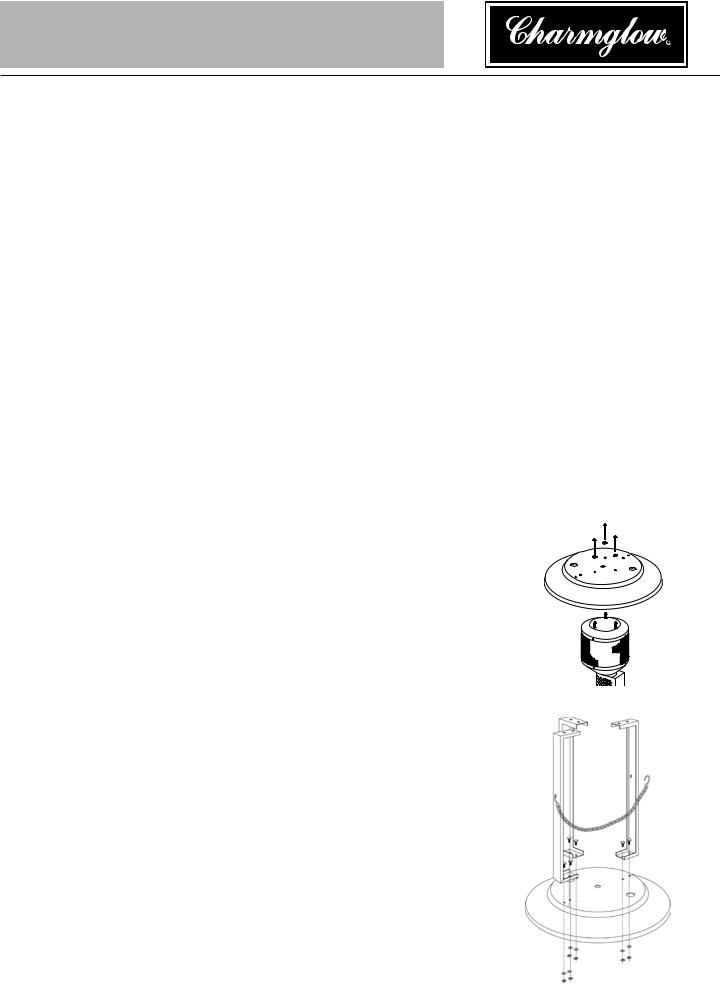
Step 1 – Attach Legs to Base
Secure Legs to Base using (2) Small Bolts, (2) Small Lock Washers and
(2) Small Nuts per leg.. Finger tighten only..
Do not fully tighten until Step 2..
Attach small ‘S’ hook on Tank Restraint Chain to left leg..
Owner’s manual: model 200605C outdoor patio heater
Contact 1.800.762.1142 for assistance. Do not return to place of purchase.
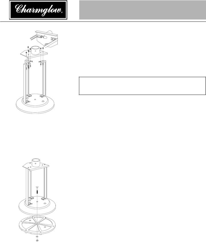
Step 2 – Attach Platform to Legs
Line up hole in Clip with small threaded hole on bottom of Platform..
Attach Clip loosely to Platform with (1) Large Screw.. Note: Do not tighten until step 9..
Using 7/16” wrench, secure Platform to Legs using (2) Small Bolts, (2) Small Lock Washers and (2) Small Nuts per Leg.. Tighten fully..
Fully tighten all nuts and bolts from Step 1..
TIP:
To tighten use a 7/16” wrench on Bolt and a 7/16” socket wrench on Nut..
Step 3 – Attach Weight Plate to Base
Lay Base Assembly on its side..
Place Weight Plate in Base, feet out..
Note: If you plan to anchor your heater permanently, be sure to line up two outer holes in Base with those in Weight Plate so that your anchor bolt will pass through both holes..
Insert Carriage Bolt through center holes of Base and Plate..
Using 9/16” wrench, secure Plate to Base using (1) Large Lock Washer and (1) Large Nut..
Place Base Assembly upright..
Owner’s manual: model 200605C outdoor patio heater
Contact 1.800.762.1142 for assistance. Do not return to place of purchase.
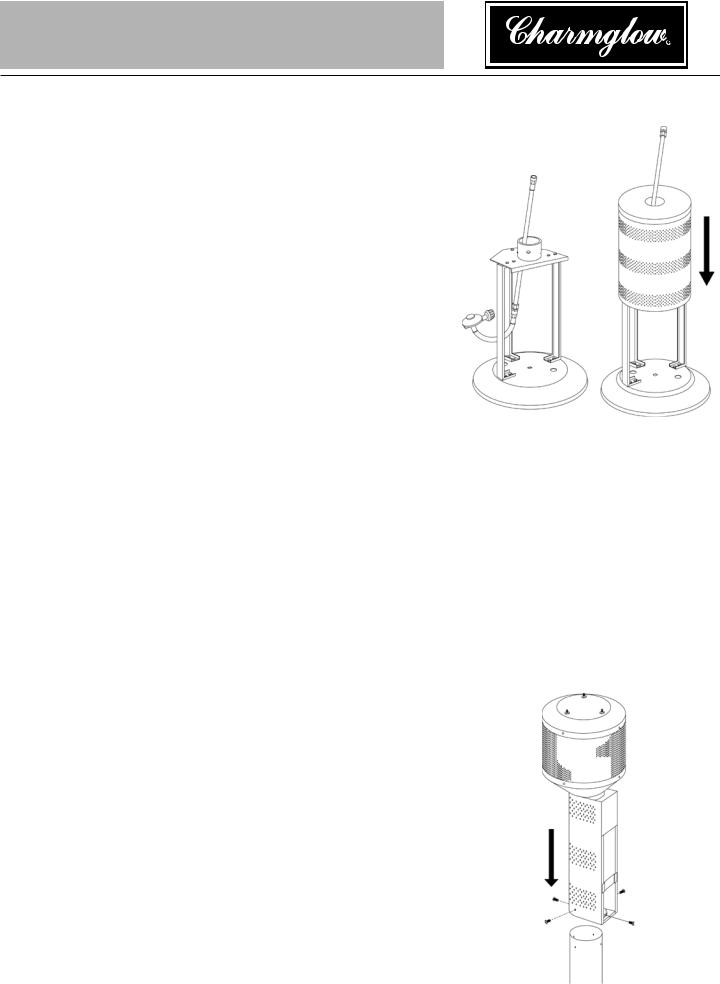
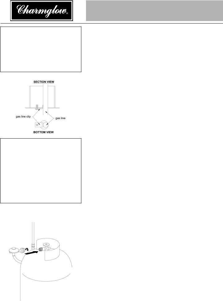
Step 4 – Insert Gas Line through Platform/Attach Shroud Cover
Insert Gas Line up through large hole in Platform from underneath between center and left leg as shown in illustration..
Slide Shroud Cover over Gas Line, then over Platform/Leg assembly until bottom of Shroud rests on Base..
Step 5 – Attach Engine to Post
Lay Engine Assembly on its side, using carton for support..
Remove and save Control Knob..
Remove and save Engine Access Panel by removing (1) black Thumbscrew from bottom of Access Door..
Disconnect wire from Igniter by gently pulling wire from back of box..
Align (4) holes in top of Post with (4) holes in bottom of Engine..
Note: One hole is at a different level than the rest.. Make sure that all 4 holes line up properly..
Insert (4) Small Screws enough to hold Engine in place.. They will be fully tightened at the end of Step 7..
Note: Do not replace Engine Access Panel until Step 13..
Owner’s manual: model 200605C outdoor patio heater
Contact 1.800.762.1142 for assistance. Do not return to place of purchase.
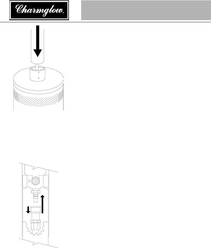
Step 6 – Attach Engine/Post to Platform
Insert end of Post without holes over Gas Line, being careful not to bend Gas Line..
Slide Post into collar of Platform so Post rests completely on Platform..
Tighten bottom three setscrews with hex (Allen) wrench supplied.. Make sure Post is perpendicular to Base..
Use top three setscrews to adjust Post’s angle as necessary..
Tighten all six setscrews..
Note: Post must be perpendicular to Base.. Failure to do so will adversely affect burner performance..
Step 7 – Connect Gas Line to Engine
Attach Gas Line to Control Valve: Pull collar of Gas Line back..
Insert Gas Line over Control Valve..
Release collar and it should lock in place.. (Tip – push Gas Line up from bottom of Post to make a good seating before releasing the collar..)
Gently tug on line to test for proper connection.. If Gas Line moves it is not properly connected.. Do not proceed until you have a proper connection..
Fully tighten the (4) screws from Step 5..
Owner’s manual: model 200605C outdoor patio heater
Contact 1.800.762.1142 for assistance. Do not return to place of purchase.
Step 8 – Assemble dome
Note: Each dome section has a pin mounted in place in the rolled bottom edge.. If necessary for proper alignment of dome sections, loosen each screw prior to further assembly and retighten after sections are aligned..
•With the large side facing up, slide a dome rib on to the same side of one dome section as the pin.. Slide two dome sections together, allowing the exposed end of the pin slide into the rolled edge of the next dome section.. Line up hole in dome with threaded hole in pin..
•Insert one Dome Screw and secure loosely..
•Repeat procedure to complete the assembly of all three sections..
•Slide Dome bolt through bottom check plate (with small center hump), being sure that the rolled edge faces down..
•Slide bolt from previous step through the center of the assembled dome sections, and be sure that the rolled edge of the check plate fits inside of the ends of the three Dome Ribs.. Also be sure that the slots in the check plate line up with the holes on the dome sections..
•Slide the other check plate over the Center bolt with the rolled edge facing up, again making sure that the plate fits inside of the Ribs and the holes line up with those in the dome..
•Spin the medium nut all the way down the bolt, clamping all of the pieces in place, making sure that all of the humps fit inside one another..
•Fully tighten all of the screws in the rolled edge..
Step 9 – Attach Dome to Emitter
Line up holes in dome assembly with the studs from the emitter assembly and lay dome assembly in place.. Secure with three nuts..
Place dome cap over center bolt, making sure that the three slots in cap lay over each Rib
Thread on finial until tight..
Owner’s manual: model 200605C outdoor patio heater |
10 |
Contact 1.800.762.1142 for assistance. Do not return to place of purchase.
Caution
Before you attempt to use a propane tank, understand all tank and propane related precautions in Section #1 - “Safety First.”
Caution
Your Charmglow® Heater has been checked at all factory connections for leaks. Recheck all connections, as movement in shipping can loosen connections. Check for leaks even if your unit was
assembled for you at the store.
Step 10 – Secure Gas Line
Make sure angled side of Gas Clip pokes up through large hole in Platform..
Tighten screw until Gas Line is held securely in place..
Stand Heater upright..
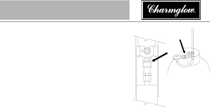
Step 11 – Connect Gas Line to Tank
The pressure regulator and hose assembly supplied with the appliance must be used and replacements must be those specified by the manufacturer..
•Slide full Propane Tank onto Heater Base..
•Attach Gas Line to Tank by turning black plastic knob clockwise over Tank valve until tight..
Note: Be careful not to kink flexible hose of Gas Line..
•Secure tank in place by attaching loose end of Tank Restraint Chain to hole in right leg..
11 |
Owner’s manual: model 200605C outdoor patio heater |
Contact 1.800.762.1142 for assistance. Do not return to place of purchase.
Step 12 – Check for Leaks
•Make 2-3 oz.. of leak check solution by mixing one part liquid dishwashing soap and three parts water..
•Turn tank valve ON..
•Check Gas Line / Control Valve for leaks:
•Spoon several drops of solution onto Gas Line and Control Valve connection..
•Inspect the solution at the connection to look for bubbles..
•If NO bubbles appear, then the connection is secure..
•If bubbles appear, there is a leak -
•Turn Tank valve OFF..
•Loosen screw on Clip..
•Release Gas Line fitting from control valve and re-attach making sure connection is secure (see Step 7)..
•Retighten Clip..
•If you continue to see bubbles after several attempts, contact 1..800..762.11 42 for assistance..
Check Gas Line / Tank valve for leaks:
•Turn tank valve ON..
•Spoon several drops of solution onto Gas Line and Tank valve connection..
•Inspect the solution at the connection to look for bubbles..
•If NO bubbles appear, then the connection is secure..
•If bubbles appear, there is a leak:
•Turn Tank valve OFF..
•Release Gas Line fitting from Tank valve and re-attach making sure connection is secure (see Step 11)..
•If you continue to see bubbles after several attempts, contact 1..800..762.11 42 for assistance..
•Turn Tank Valve OFF..
Owner’s manual: model 200605C outdoor patio heater |
12 |
Contact 1.800.762.1142 for assistance. Do not return to place of purchase.
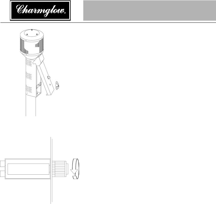
Step 13 – Replace Engine Access Panel
•Slide Igniter wire onto Igniter post..
•Slide tab at top of Access Panel into slot in Emitter bottom..
•Rotate Panel down until holes line up at bottom..
•Secure Access Panel in place with thumbscrew..
•Replace Control Knob..
Step 14 – Install Igniter Battery
Note: This step is required only for models with electronic ignition..
•Remove battery cover cap by turning cap counterclockwise..
•Install (1) AA battery.. Negative end of battery goes in first..
•Replace battery cover cap by turning cap clockwise..
Note: Once you have successfully completed assembly steps 1-14 you are ready to begin operating your heater..
13 |
Owner’s manual: model 200605C outdoor patio heater |
 Loading...