


KLS-E and KPS-E Series
ELECTRIC TRI-LEG STATIONARY KETTLE AND ELECTRIC PEDESTAL STATIONARY KETTLE INSTALLATION – OPERATION – MAINTENANCE
BLODGETT OVEN COMPANY
www.blodgett.com
44 Lakeside Avenue, Burlington, Vermont 05401 USA Telephone: (802) 658-6600 Fax: (802) 864-0183
S00050 Rev1C (12/09)
IMPORTANT NOTES FOR INSTALLATION AND OPERATION
It is recommended that this manual be read thoroughly and that all instructions be followed carefully.
This is the safety alert symbol. It is used to alert you to potential personal injury hazards. Obey all safety messages that follow this symbol to avoid possible injury or death.
WARNING: Improper installation, operation, adjustment, alteration, service or maintenance can cause property damage, injury or death. Read the installation, operating and maintenance instructions thoroughly before installing, operating or servicing this equipment.
NOTICE: Contact the factory, the factory representative or local service company to perform maintenance and repairs.
Intended for commercial use only. Not for household use.
This manual should be retained for future reference.
2
|
TABLE OF CONTENTS |
|
DESCRIPTION |
PAGE |
|
1.0 |
Service Connections ................................................................................................ |
4 |
2.0 |
Installation Instructions............................................................................................. |
6 |
3.0 |
Description ............................................................................................................... |
8 |
4.0 |
Capacities ................................................................................................................ |
8 |
5.0 |
Functioning Mode..................................................................................................... |
8 |
6.0 |
Operation Instructions .............................................................................................. |
9 |
7.0 |
Cleaning Instruction ............................................................................................... |
11 |
8.0 |
General Maintenance............................................................................................. |
14 |
9.0 |
Troubleshooting ..................................................................................................... |
14 |
APPENDIX A Material Data Safety Sheet ........................................................................ |
17 |
|
3
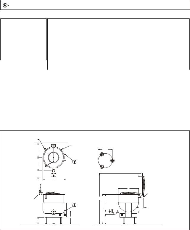
1.0 SERVICE CONNECTIONS
Models: KLS-20E, KLS-30E, KLS-40E, KLS-60E, KLS-80E and KLS-100E tri-leg stationary kettles
ELECTRICAL CONNECTION TO BE AS SPECIFIED ON DATA PLATE
ELECTRICAL CHARACTERISTICS
Available kW
MODEL |
STD. |
OPT. |
|
|
|
KLS-20E |
12 |
N/A |
|
|
|
KLS-30E |
15 |
N/A |
|
|
|
KLS-40E |
18 |
24 |
|
|
|
KLS-60E |
18 |
24, 33 |
|
|
|
KLS-80E |
18 |
24, 33 |
|
|
|
KLS-100E |
24 |
33 |
|
|
|
AMPS PER LINE
kW |
PHASE |
208V |
220V |
240V |
380V |
415V |
480V |
|
|
|
|
|
|
|
|
|
|
|
1 |
57.7 |
54.5 |
50.0 |
N/A |
N/A |
N/A |
|
12 |
|
|
|
|
|
|
|
|
3 |
33.3 |
31.5 |
28.9 |
18.2 |
16.7 |
14.4 |
||
|
||||||||
|
|
|
|
|
|
|
|
|
|
1 |
72.1 |
68.2 |
62.5 |
N/A |
N/A |
N/A |
|
15 |
|
|
|
|
|
|
|
|
3 |
41.6 |
39.4 |
36.1 |
22.8 |
20.9 |
18.0 |
||
|
||||||||
|
|
|
|
|
|
|
|
|
18 |
1 |
86.5 |
81.8 |
75.0 |
N/A |
N/A |
N/A |
|
3 |
50.0 |
47.2 |
43.3 |
27.3 |
25.0 |
21.7 |
||
|
||||||||
|
|
|
|
|
|
|
|
|
24 |
3 |
66.6 |
63.0 |
57.7 |
36.5 |
33.4 |
28.9 |
|
33 |
3 |
91.6 |
86.6 |
79.4 |
50.1 |
45.9 |
39.7 |
DIMENSIONS
MODEL |
CAPACITY |
UNITS |
A |
B |
C |
D |
E |
F(2") |
F(3") |
G(2") |
G(3") |
H |
J |
K |
L |
|
|
|
|
|
|
|
|
|
|
|
|
|
|
|
|
|
|
KLS-20E |
20 U.S. gal. |
inches |
21 |
18 |
38 |
23.75 |
18.5 |
14.75 |
15.5 |
18 |
17.5 |
14 |
21 |
60.5 |
16.75 |
|
76 litres |
mm |
533 |
457 |
965 |
629 |
470 |
375 |
394 |
457 |
445 |
356 |
533 |
1537 |
425 |
||
|
||||||||||||||||
KLS-30E |
30 U.S. gal. |
inches |
24 |
20 |
38 |
27.75 |
20 |
16 |
16.5 |
15.75 |
15.25 |
12.5 |
19 |
63.5 |
18.312 |
|
114 litres |
mm |
610 |
508 |
965 |
705 |
508 |
406 |
419 |
400 |
387 |
318 |
483 |
1613 |
465 |
||
|
||||||||||||||||
KLS-40E |
40 U.S. gal. |
inches |
26 |
22.5 |
38 |
29.75 |
21 |
17 |
18 |
13.5 |
13 |
9 |
17 |
65 |
19.938 |
|
|
|
|
|
|
|
|
|
|
|
|
|
|
|
|
||
|
152 litres |
mm |
660 |
572 |
965 |
756 |
533 |
432 |
457 |
343 |
330 |
229 |
432 |
1651 |
506 |
|
KLS-60E |
60 U.S. gal. |
inches |
29.5 |
26 |
42 |
33.75 |
19 |
18 |
19.25 |
14 |
13.5 |
11 |
17.25 |
75 |
23.125 |
|
227 litres |
mm |
749 |
660 |
1067 |
857 |
483 |
457 |
489 |
356 |
343 |
280 |
438 |
1905 |
|
||
|
587 |
|||||||||||||||
KLS-80E |
80 U.S. gal. |
inches |
33 |
28 |
45 |
36.75 |
20.5 |
19.5 |
20.5 |
15 |
14.5 |
12.75 |
18 |
81 |
26.25 |
|
303 litres |
mm |
838 |
711 |
1143 |
933 |
521 |
495 |
521 |
381 |
368 |
324 |
458 |
2058 |
|
||
|
667 |
|||||||||||||||
KLS-100E |
100 U.S. gal. |
inches |
35.5 |
30 |
48 |
40 |
22 |
21.5 |
22.5 |
15 |
14.5 |
13 |
20.5 |
87 |
29.438 |
|
379 litres |
mm |
902 |
762 |
1219 |
1016 |
559 |
546 |
572 |
381 |
368 |
330 |
521 |
2210 |
|
||
|
748 |
SAFETY RELIEF VALVE |
WALL |
|
|
|
AIR VENT |
E |
|
2" VALVE: |
|
CLOSED 5.13[130] |
|
OPENED 6.88[175] |
|
F |
|
3” VALVE |
|
CLOSED 7.88[200] |
|
OPENED 10.13[257] |
|
|
D |
OPTIONAL FAUCET
ALLOW DIMENSION “D”
ADDITIONAL 6[152]
J
H
DIMENSIONS ARE IN INCHES [MM]
ØL
FLANGED FOOT DETAIL
4 EQUALLY SPACED Ø7/16" [11mm] HOLES ON 3 [76] B.C.
A
K
B |
C |
G |
SPRING ASSIST
HINGES ON 60, 80 AND 100 GALLON KETTLES
2-1/2" ON SPRING ASSIST HINGES
7" ON YOKE TYPE HINGES (STANDARD ON 20, 30 AND 40 GALLON KETTLES)
4
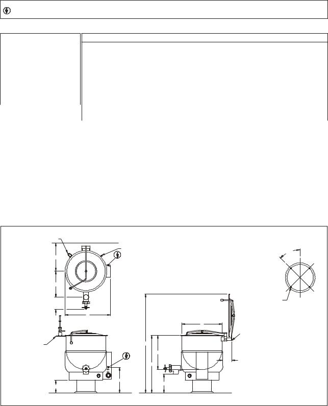
1.0 SERVICE CONNECTIONS (CONTINUED)
Models: KPS-20E, KPS-30E, KPS-40E, KPS-60E, KPS-80E and KPS-100E pedestal base stationary kettles
- ELECTRICAL CONNECTION TO BE AS SPECIFIED ON DATA PLATE
ELECTRICAL CHARACTERISTICS
Available kW
MODEL |
STD. |
OPT. |
|
|
|
KPS-20E |
12 |
N/A |
|
|
|
KPS-30E |
15 |
N/A |
|
|
|
KPS-40E |
18 |
24 |
|
|
|
KPS-60E |
18 |
24, 33 |
|
|
|
KPS-80E |
18 |
24, 33 |
|
|
|
KPS-100E |
24 |
33 |
|
|
|
AMPS PER LINE
kW |
PHASE |
208V |
220V |
240V |
380V |
415V |
480V |
|
|
|
|
|
|
|
|
|
|
12 |
1 |
57.7 |
54.5 |
50.0 |
N/A |
N/A |
N/A |
|
|
|
|
|
|
|
|
||
3 |
33.3 |
31.5 |
28.9 |
18.2 |
16.7 |
14.4 |
||
|
||||||||
|
|
|
|
|
|
|
|
|
15 |
1 |
72.1 |
68.2 |
62.5 |
N/A |
N/A |
N/A |
|
3 |
41.6 |
39.4 |
36.1 |
22.8 |
20.9 |
18.0 |
||
|
||||||||
18 |
1 |
86.5 |
81.8 |
75.0 |
N/A |
N/A |
N/A |
|
|
|
|
|
|
|
|
||
3 |
50.0 |
47.2 |
43.3 |
27.3 |
25.0 |
21.7 |
||
|
||||||||
|
|
|
|
|
|
|
|
|
24 |
3 |
66.6 |
63.0 |
57.7 |
36.5 |
33.4 |
28.9 |
|
|
|
|
|
|
|
|
|
|
33 |
3 |
91.6 |
86.6 |
79.4 |
50.1 |
45.9 |
39.7 |
|
|
|
|
|
|
|
|
|
DIMENSIONS
MODEL |
CAPACITY |
UNITS |
A |
B |
C |
D |
E |
F(2") |
F(3") |
G(2") |
G(3") |
H |
J |
K |
|
|
|
|
|
|
|
|
|
|
|
|
|
|
|
|
|
KPS-20E |
20 U.S. gal. |
inches |
21 |
18 |
38 |
23.75 |
18.5 |
14.75 |
15.5 |
18 |
17.5 |
14 |
21 |
60.5 |
|
76 litres |
mm |
533 |
457 |
965 |
629 |
470 |
375 |
394 |
457 |
445 |
356 |
533 |
1537 |
||
|
|||||||||||||||
KPS-30E |
30 U.S. gal. |
inches |
24 |
20 |
38 |
27.75 |
20 |
16 |
16.5 |
15.75 |
15.25 |
12.5 |
19 |
63.5 |
|
114 litres |
mm |
610 |
508 |
965 |
705 |
508 |
406 |
419 |
400 |
387 |
318 |
483 |
1613 |
||
|
|||||||||||||||
KPS-40E |
40 U.S. gal. |
inches |
26 |
22.5 |
38 |
29.75 |
21 |
17 |
18 |
13.5 |
13 |
9 |
17 |
65 |
|
152 litres |
mm |
660 |
572 |
965 |
756 |
533 |
432 |
457 |
343 |
330 |
229 |
432 |
1651 |
||
|
|||||||||||||||
KPS-60E |
60 U.S. gal. |
inches |
29.5 |
26 |
42 |
33.75 |
19 |
18 |
19.25 |
14 |
13.5 |
11 |
17.25 |
75 |
|
227 litres |
mm |
749 |
660 |
1067 |
857 |
483 |
457 |
489 |
356 |
343 |
280 |
438 |
1905 |
||
|
|||||||||||||||
KPS-80E |
80 U.S. gal. |
inches |
33 |
28 |
45 |
36.75 |
20.5 |
19.5 |
20.5 |
15 |
14.5 |
12.75 |
18 |
81 |
|
303 litres |
mm |
838 |
711 |
1143 |
933 |
521 |
495 |
521 |
381 |
368 |
324 |
458 |
2058 |
||
|
|||||||||||||||
KPS-100E |
100 U.S. gal. |
inches |
35.5 |
30 |
48 |
40 |
22 |
21.5 |
22.5 |
15 |
14.5 |
13 |
20.5 |
87 |
|
379 litres |
mm |
902 |
762 |
1219 |
1016 |
559 |
546 |
572 |
381 |
368 |
330 |
521 |
2210 |
||
|
SAFETY RELIEF VALVE |
WALL |
|
|
E |
|
2" VALVE: |
|
|
CLOSED 5.13[130] |
F |
|
OPENED 6.88[175] |
|
|
|
|
|
3” VALVE |
|
|
CLOSED 7.88[200] |
|
|
OPENED 10.13[257] |
|
|
|
|
D |
OPTIONAL FAUCET |
|
|
ALLOW DIMENSION “D” |
|
|
ADDITIONAL 6[152] |
|
|
J
H
DIMENSIONS ARE IN INCHES [MM]
PEDESTAL DETAIL
AIR VENT
45°
|
|
4 HOLES Ø 7/16 [11] |
FRONT |
|
|
EQUALLY SPACED |
|
|
|
|
|
|
A |
SPRING ASSIST |
|
|
|
|
|
|
|
HINGES ON 60, 80 AND |
|
|
|
100 GALLON KETTLES |
|
K |
|
2-1/2" ON SPRING |
|
|
|
|
|
B |
|
ASSIST HINGES |
|
C |
|
7" ON YOKE TYPE HINGES |
|
|
(STANDARD ON 20, 30 |
|
|
|
|
|
|
|
|
AND 40 GALLON |
|
|
G |
KETTLES) |
|
|
|
|
5
2.0 INSTALLATION INSTRUCTIONS
UNPACKING
Immediately after unpacking, check for possible shipping damage. If the kettle is found to be damaged, save the packaging material and contact the carrier within 15 days of delivery.
Before installing, verify that the electrical service agrees with the specifications on the rating plate located on the lower rear of the kettle. If the supply and equipment requirements do not agree, contact your dealer or Blodgett.
Select a location with drainage directly below the tangent draw-off. Allow sufficient rear clearance from wall for kettle cover to lift upright freely and completely without obstructions.
INSTALLATION
1.The kettle must be installed in accordance with: State and/or local codes.
In the USA, the National Electrical code, ANSI/NFPA-70 (latest edition). In Canada, the Canadian Electrical Code, Part 1, CSA Standard C22.1 (latest edition).
2.Set the kettle in the installation location.
3.With the kettle in position, place a carpenter‟s level on top of the kettle and turn the adjustable feet to level kettle side-to-side and front to back. On pedestal base models use shims to level kettle.
4.Mark hole locations on floor through anchoring holes provided in flanged adjustable feet, or holes provided on pedestal base.
5.Remove kettle and drill holes in locations marked on the floor (see installation diagram). Insert proper anchoring devices to accommodate 5/16" size lag bolts (not supplied).
6.Reposition kettle. Re-level kettle by making necessary adjustments on flanged feet or shims.
7.Bolt down kettle and seal with Silastic or other equivalent sealing compound. Sealant must be applied not only to bolt heads but also around flanges or pedestal base making contact with floor surface to fulfill NSF requirements. Wipe off excess sealant immediately.
6

WARNING: Disconnect the electrical power supply and place a tag at the disconnect switch to indicate that you are working on the circuit.
ELECTRICAL CONNECTIONS
A Control Box with power supply equivalent to electrical rating of the kettle should be located conveniently nearby.
Remove the wiring compartment cover and make electrical connections per wiring diagram located inside the control housing cover panel. A waterproof electrical connection from power supply to rear of control housing must be provided.
Kettle must be grounded in accordance with requirements of the National Electrical Code or applicable local codes.
Ground kettle to terminal provided in control housing.
Once proper connections are made, replace wiring compartment cover, turn power ON and check for proper operation.
SERVICE CONNECTIONS
All internal wiring for the kettle is complete.
If faucet is provided connect water supply and check for proper operation.
INSTALLATION CODES AND STANDARDS
Your electric tilting kettle must be installed in accordance with:
1.State, provincial and local codes, or in the absence of local codes, with: C.S.A. C22.1 Canadian Electrical Code, Part 1, or in the U.S.A., the National Electrical Code ANSI/NFPA-70 (latest edition).
2.ANSI NFPA Standard #96, “Vapor Removal from Cooking Equipment,” (latest edition), available from the National Fire Protection Association, Batterymarch Park, Quincy, MA, 02269.
7
3.0 DESCRIPTION
All electrically powered kettles described and referred to in this manual are pressure vessels of a double-wall construction forming a sealed jacket (chamber) enveloping the lower two thirds of the kettle bowl surface.
The kettle bowl is the container for the food product which ideally should be a liquid or semi-liquid consistency to achieve complete contact with the bowl surface and thus fully absorb the heat transmitted through that surface from the pressurized steam generated in the kettle jacket.
The jacket is intended to function as a self contained sealed chamber with a permanent solution of water and antifreeze sufficient not only to immerse and thereby protect replaceable electric heating elements, but also provide the steam source during the steam generating process.
The heating elements are thermostatically dial controlled to provide precise temperatures throughout the range from slow simmer to rolling boil.
All stationary kettles are intended to be permanently floor mounted on legs with adjustable flanged feet (KLS-E models) or pedestals (KLP-E models).
All kettles are equipped with a hinged counterbalanced stainless steel lid covering the kettle bowl opening, a sanitary stainless steel tangent draw-off valve for the removal of the food product from the kettle bowl, and a safety relief valve plumbed to the kettle jacket.
4.0 CAPACITIES
All models are suffixed with either - 20, - 30, - 40, - 60, - 80 or -100 to indicate the capacity of that kettle in US gallons. Thus a KLS-40E indicates a two thirds jacketed electrically powered steam kettle mounted on legs with a capacity of 40 US gallons.
5.0 FUNCTIONING MODE
All electrically powered self steam generating kettles consist of a jacket charged with a solution of water and antifreeze sufficient to completely immerse and protect replaceable electric heating elements.
To minimize tampering, the Safety Valve is plumbed toward the rear of the kettle jacket. Should any component malfunction and cause the pressure in the jacket to reach the rated pressure of the kettle, this protective device will open automatically and release excessive pressurized steam.
When the Power Switch is turned ON and the Temperature Control (Thermostat) Knob dialed simultaneously, TEMPERATURE pilot light will come on and contactors will close to allow power to elements. Steam generation will commence and continue until the water contained in the jacket reaches the thermostatic temperature, manually preselected, at which point the Temperature (thermostat) Control will de-energize and open the contactors cutting off power to heating elements and TEMPERATURE pilot light will go off. When the temperature of the water in the jacket drops slightly, the cycle will repeat itself thus making it possible to maintain any selected precise cooking mode temperature.
The temperature required for the cooking process to function adequately must be greater than the boiling point of the liquid food product. Further, the higher the temperature, the greater the steam
8
 Loading...