


FCC Warning
The equipment has been tested and found to comply with the limits for a Class B device, pursuant to Part 15 of the FCC Rules. These limits are designed to provide reasonable protection against harmful interference in a residential installation. This equipment generates, uses, and can radiate radio frequency energy, and, if not installed and used in accordance with instructions, may cause harmful interference with radio communications. However, there is no guarantee that radio interference will not occur in particular installation. If this equipment does cause harmful interference to radio or television reception, which can be determined by turning the equipment off and on, the user is encouraged to contact the dealer or an experienced Radio/TV technician for help.
You are cautioned that any changes or modifications not expressly approved in this manual could void your authority to operate this equipment.
Owner’s Record
The model and warranty numbers are located on the top of the unit. Record the warranty (serial) number in the space provided below. Refer to these numbers whenever you call upon your Blaupunkt dealer regarding this product.
Warranty Number _____________
Attach Sales Receipt Here
2

Table of Contents
English |
|
FCC Warning .................................................... |
2 |
Owner’s Record ................................................ |
2 |
Features ............................................................ |
4 |
Precautions ....................................................... |
4 |
Detachable Face .............................................. |
5 |
Electrical Connections and Installation ............ |
6 |
Installation ........................................................ |
8 |
Maintenance ................................................... |
10 |
Specifications ................................................. |
11 |
Location of Controls ....................................... |
12 |
Instructions—General Operation ................... |
13 |
Audio Operation .............................................. |
14 |
Radio Operation ............................................. |
14 |
Cassette Player Operation ............................. |
16 |
Auxiliary Input Jack ........................................ |
17 |
Changer Control ............................................. |
17 |
Changer TPM ................................................. |
19 |
Direct Software Control Menu ........................ |
20 |
Troubleshooting Guide ................................... |
23 |
Español |
|
Advertencias FCC ........................................ |
47 |
Registro del Propietario ................................ |
47 |
Características .............................................. |
48 |
Precauciones ................................................ |
48 |
Panel Frontal Desmontable (Carátula) ........ |
49 |
Conexiones Eléctricas e Instalación ............ |
50 |
Instalación .................................................... |
52 |
Mantenimiento .............................................. |
54 |
Especificaciones ........................................... |
55 |
Ubicación de los Controles .......................... |
56 |
Instrucciones de Funcionamiento ................ |
57 |
Funcionamiento de Audio ............................ |
58 |
Funcionamiento de la Radio ........................ |
59 |
Funcionamiento del Cassette ...................... |
60 |
Toma de Entrada Auxiliar ............................. |
61 |
Control de Cambiador ................................. |
62 |
Memoria de Programación de Pistas del |
|
Cambiador ........................................... |
64 |
Menu ............................................................. |
65 |
Guía para la Solución de Problemas ........... |
69 |
Français |
|
Avertissement de la FCC ............................... |
24 |
Archive du Propriétaire ................................... |
24 |
Caractéristiques .............................................. |
25 |
Précautions à Prendre .................................... |
25 |
Face Avant Amovible ..................................... |
26 |
Raccordements Électriques et Installation .... |
27 |
Installation ...................................................... |
29 |
Entretien ......................................................... |
31 |
Spécifications ................................................. |
32 |
Emplacements des Commandes ................... |
33 |
Mode d’Emploi/Fonctionnement Général ...... |
34 |
Fonctionnement de la Audio .......................... |
35 |
Fonctionnement de la Radio .......................... |
35 |
Fonctionnement du Lecteur de Cassette ....... |
37 |
Prise Auxiliare ................................................. |
38 |
Commande du Changeur ............................... |
39 |
Mémoire de Programme des plages du |
|
Changeur ................................................ |
41 |
Menu ............................................................... |
42 |
Guide de Dépannage ..................................... |
46 |
Portuguese |
|
Aviso da FCC ............................................... |
71 |
Registro do Proprietário ............................... |
71 |
Características .............................................. |
72 |
Precauções ................................................... |
72 |
Painel Removível .......................................... |
73 |
Conexões Eléctricas e Instalação ................ |
74 |
Instalação ..................................................... |
76 |
Manutenção .................................................. |
78 |
Especificações .............................................. |
79 |
Posição dos Controles ................................. |
80 |
Instruções-Funcionamento Geral ................. |
81 |
Funcionamento do Audio ............................. |
82 |
Funcionamento do Rádio ............................. |
83 |
Funcionamento do Toca-Fitas ..................... |
84 |
Tomada para en Trada Auxilier ................... |
85 |
Controle de Cambiador ............................... |
86 |
Memória de Programação de Faixas do |
|
Cambiador ........................................... |
88 |
Menu ............................................................. |
89 |
Guia para Solução de Problemas ................ |
93 |
3

ENGLISH
Features
Congratulations on your purchase of this Blaupunkt Cassette Receiver. Its Codem III-US FM/AM
Tuner and Full-Logic, Soft-Touch Cassette Player provide the ultimate in sound reproduction. Its high-power amplifier and 4-Channel RCA preamp output provide you with tremendous system configuration flexibility. It’s auxiliary input jack lets you easily incorporate portable audio equipment, such as a CD or DAT player, into your car’s sound system.
• Codem III-US Tuner Features: |
• Audio Features: |
– Multipath Management |
– 35 Watts x 4 Channel Integrated Amplifier |
– ASU Electrical Impulse Noise Reduction |
– Dual-Level Fader |
– Superior AM Frequency Response |
– Over 3 Volts of Distortion-Free Output |
– 18 FM/6 AM Presets, Including 6 FM & |
4-Channel, Low Impendance (200 Ω) Preamplifier |
6 AM Travelstore Presets |
– 2-Channel RCA Preamp Output Harness Included |
– Station & Preset Scans |
– Bass,Treble, Balance, Fader Controls |
– Station Naming |
– Source Tone & Loudness-Level Memory |
– Tuner Timer |
– Adjustable Maximum Turn-On Volume & Mute |
– Local/Distant Seek & Manual Tuning |
– Auxiliary Input |
• Cassette Player Features: |
• Other Features: |
– Full-Logic Autoreverse Cassette Mechanism |
– 21 Direct Software Control Menu Options |
– 9-Track Super CPS Cassette Program Search – Detachable Face with Hardshell Case |
|
– Accelerated Fast-Forward and Rewind |
– Amber Illumination |
– Radio Monitor with Radio Preset Acess |
– Source Display Priority |
– Track Up, Down, Scan, Repeat, and Pause |
– Clock/Ignition-Off Clock Recall |
– Adjustable Blank Skip |
– 180 x 50 x 155 mm (7 x 2 x 61/8 in.) |
– Hard Permalloy Tape Head |
DIN/ISO Chassis |
– Pinch Roller Release |
– Detachable Wire Harness w/Bullet Connectors |
|
– Snap-In DIN Sleeve & Mounting Hardware |
• CD Changer-Control Features: |
– Side-Bracket Compatible |
– CDC-A05 or CDC-A071 Changer Control |
|
|
– Disc Naming, Disc Select-by-Name, Disc List |
Your unit’s fully-detachable front faceplate |
|
– Disc/Track Up/Down |
||
makes the unit useless to would-be thieves. |
||
– Disc/Track Scan, Repeat, Track Mix 1 & 2 |
||
|
||
– Track Program Memory (TPM) |
Designed, Engineered and Manufactured |
|
– Cue/Review, Pause/Play |
||
– Last Position Memory |
by Blaupunkt |
Traffic Safety and Precautions
•Do not adjust your unit in difficult driving conditions that demand your full attention.
•As the driver of a motor vehicle, it is your responsibility to pay attention to the traffic situation at all times. Never use your unit in a way that could distract you.
•Always make sure that you are still able to hear any warning signals coming from outside of the vehicle, such as police or fire engine sirens, so that you can react accordingly.
•If your vehicle was parked in direct sunlight resulting in a considerable rise in temperature inside the vehicle, allow the unit to cool off before operating your unit.
•You are cautioned that any changes or modifications not expressly approved in this manual could void your warranty.
•Car Wash precaution - If you have a motorized antenna, make sure to turn off the unit – not just the tuner – so that the antenna is lowered and antenna damage is prevented!
4
Detachable Face
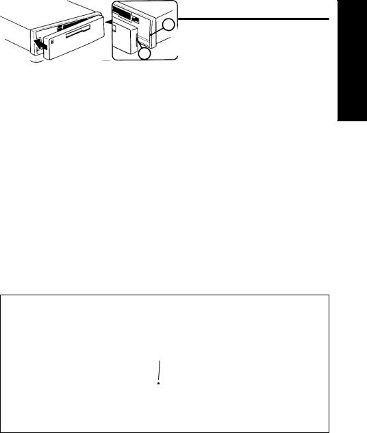
Detaching & Attaching the Face:
The face of this unit can be detached and taken with you to prevent it from being stolen.
Detaching the Face:
Before detaching the face, be sure to press the PWR Button first. Then press the REL (Release) Button and detach the face by gently pulling it off as illustrated.
Note: Do not pull it straight out from the chassis. Be sure not to drop the face when detaching it from the chassis.
Attaching the Face:
Apply the right hand side of the face to the chassis by sliding (part B) of the face to (part A) at the front of the chassis. Gently push the left side of the face against the front of the chassis until it snaps into place.
Note: Make sure that the face is inserted right side up. Do not press against the display window. Do not press hard against the face when attaching it to the chassis, it may be easily attached with gentle pressure. When carrying the face with you, put it in the carrying case. Do not expose the face to direct sunlight, heat sources such as hot air ducts or leave it in a humid place. Never leave it on the dash board of a vehicle parked in direct sunlight, where there may be a considerable rise in temperature inside the vehicle.
Affixing Faceplate For Retail Display:
The faceplate can be affixed to the unit’s chassis, which is desirable for a retail display, for example.
To affix the faceplate:
Insert the black bolt into the hole at the left front of the top of the radio. See* below.
E N G L I S H
*
A
B
5

Electrical Connections and Installation
@/<?#&*>@! To avoid the aggravation of costly mistakes and serious damage that could make you feel this way, please carefully read all of the instructions before you begin. Carefully follow all instructions. You’ll be glad you did!
GENERAL RECOMMENDATIONS
•If you’re not confident that you can install the unit correctly, have it installed by a qualified Blaupunkt installation technician.
•Use this unit only with negative ground 12 Volt (11-16 Volt) direct current (DC).
•Be sure to detach the faceplate before you start to connect or install the unit.
•Don’t assume that a seemingly matching wire harness in the vehicle has leads that match the leads of the unit’s wire harness.
•We recommend making and testing all electrical connections before installing the unit. Connect the leads (wires) according to instructions and diagram below.
ELECTRICAL CONNECTION INSTRUCTIONS
1.Disconnect the vehicle battery’s negative terminal before making connections.
2.Connect the speakers and/or external amplifiers (if you have any) following the guidelines in the SPEAKER CONNECTION section below.
3.Connect the blue (trigger output) lead to an antenna motor trigger switch input terminal (if you have one). (Maximum amperage required must not exceed 150mA.)
4.If you have an external amplifier, connect the blue/white lead to the amplifier’s trigger switch terminal. DO NOT connect the blue/white lead to the antenna’s power supply input. (Maximum amperage required must not exceed 150mA.)
5.If you have a cellular telephone set that has a mute lead (lead that supplies constant ground when telephone is in use), connect it to the dark green lead.
6.Connect the black (power ground) lead to a grounded metal part on the vehicle. We recommend grounding all audio system black ground leads (receiver, external amplifier, etc.) to a common grounding point, preferably a non-painted surface under the instrument panel.
7.Connect the yellow (constant power) input lead to a source of constant battery power, preferably a terminal to an appropriate slot in the fuse box.
8.Connect the red (turn-on power) input lead only after the other leads are connected. Be sure to connect the red lead to a positive (+) 12 Volt power terminal that is energized only when the ignition key is set to the on position or accessory position.
9.Cover the ends of any unused leads with electrical tape. This will prevent them from touching the vehicle or each other and causing a short-circuit and damage to the unit or vehicle.
10.Reconnect the vehicle’s battery.
11.Verify that no fuses have blown.
12.Plug the harness into the unit.
13.Attach the faceplate and test the unit.
Once the connections have been successfully made, you can begin to mount the unit.
SPEAKER CONNECTIONS
The unit’s Dual-Level Fader allows you to fade between the front and the rear channels using either the front and/or rear speaker leads and/or the rear preamp outputs, providing you tremendous flexibility in configuring your speaker arrangement:
•You can connect a speaker (regular, co-axial or tri-axial speakers or component speaker system, all hereafter referred to simply as “speaker”) to each of the units’ four pairs of speaker leads.
•You can connect the 2 RCA preamp outputs to multiple external amplifiers and power multiple speakers or speaker systems through the amplifiers. (Blaupunkt amplifiers and speakers available separately). To add front preamp output, purchase Blaupunkt part 8634494218, which is included in the CDC-A05 and CDC-A071 changers’ harnesses (see page 11).
•You can use a either or both of these two methods.
Connecting the Speaker Leads |
|
To prevent short circuits or serious damage to the unit and/or speakers: |
6 |
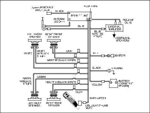
•Connect the speaker leads only as indicated in the wiring diagram. Disconnect the vehicle battery’s negative terminal before making connections.
•Only use speakers that have impedance ratings of 4 ohms or higher and have power-handling capabilities greater than the receiver’s stated power level.
•The unit’s internal amplifier is designed to handle a 4-ohm load on each pair of speaker leads.
•DON’T connect two speakers to a single pair of speaker leads (“in parallel”) unless both speakers each have at least 8 ohms impedance.
•DON’T connect the left and right speaker leads to each other or to the same speakers.
•DON’T connect the front and rear speaker leads to each other or to the same speakers.
•DON’T connect the negative speaker leads to each other.
•DON’T connect the positive speaker leads to each other.
•DON’T connect any active speakers (with built-in amplifiers) to the speaker leads unless their owner’s manuals specifically state that this is O.K.
•Cover the ends of any unused leads with electrical tape. This will prevent them from touching the vehicle or each other and causing a short-circuit and damage to the receiver or vehicle.
Connecting the Pre-Amp Outputs to External Amplifier(s)
To prevent short circuits or serious damage to the receiver, amplifier, and/or speakers:
•Follow the amplifier’s instructions on how to connect the unit’s preamp outputs to the amplifier(s) and connect the speaker(s) directly to the amplifier.
ANTENNA MOTOR |
|
TRIGGER SWITCH |
SWITCH |
|
7

Installation
Recommendations
•Carefully choose the mounting location so that the unit won’t interfere with normal driving.
•Avoid mounting locations where the unit would be subject to high temperatures, such as from direct sunlight or hot air from the heater, or where it would subject to dust, dirt or excessive vibration.
•The illustration below shows a typical installation, however, you may need to adjust the installation, depending on the unit. If you have questions or need additional installation hardware, consult your Blaupunkt dealer.
•Make sure the unit is firmly anchored (preferably at both front and back) and does not vibrate.
Mounting Hardware
|
|
|
|
|
|
|
|
|
|
|
|
|
|
(1) |
(2) |
|
(3) |
|
|
|
|
|
|
||||
|
|
|
||||
Mounting Strap |
|
|
||||
Sleeve |
|
|
||||
|
and Screw |
Release Keys |
||||
|
|
|||||
|
|
|
|
|
|
|
Mounting The Unit in Most Dashboards
1Install the Sleeve (1) in the dashboard.
2Select and bend the appropriate tabs to hold the sleeve firmly in place.
3A. Attach the Mounting Strap (2) to the underside of the dashboard, using screw.
B. Attach the back of the unit to the mounting strap using the support stem bolt and hardware.
Bend these tabs
8
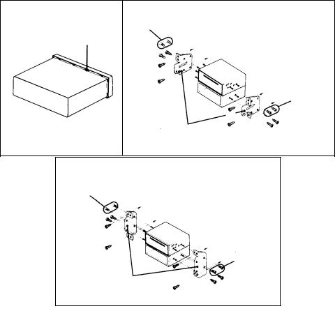
Mounting the Unit in a Japanese Car
You may have difficulty mounting this unit in some Japanese cars that have ISO mounting features (side-bracket mounting systems). In this case, consult your Blaupunkt dealer.
1Run a blade along the slits on the back of the front trim ring and separate it from the unit. Save the trim ring and related hardware in case you ever in case you ever want to install the unit in another vehicle.
2Use the vehicle’s own mounting hardware to attach the unit.
1 |
2 TOYOTA |
|
max. size M5x8 |
|
Slit |
|
to |
max. size M5x8
Bracket
Support
2 NISSAN
max. size M5x8
to dashboard/center console
max. size M5x8
Bracket
Support
9
 Loading...