


CR67
Cassette
t!P
Control
~~tQpedi~
i
cassette et
c~~t~~le
de
chanlelrr
6
Receptor
cun
Cassette
y
Control
Camhiador
Radii-C~ssete
corn
CantrQ”le
par
t~~hi~d~r
C
Bosch Group

FCC Warning
The equipment has been tested and found to comply with the limits for a Class B device, pursuant
to Part 15 of the FCC Rules. These limits are designed to provide reasonable protection against
harmful interference in a residential installation. This equipment generates, uses, and can radiate
radio frequency energy, and, if not installed and used in accordance with instructions, may cause
harmful interference with radio communications. However, there is no guarantee that radio
interference will not occur in particular installation. If this equipment does cause harmful
interference to radio or television reception, which can be determined by turning the equipment off
and on, the user is encouraged to contact the dealer or an experienced Radio/TV technician for
help.
You are cautioned that any changes or modifications not expressly approved in this manual could
void your authority to operate this equipment.
Owner’s Record
The model and warranty numbers are located on the top of the unit. Record the warranty (serial)
number in the space provided below. Refer to these numbers whenever you call upon your
Blaupunkt dealer regarding this product.
Warranty Number
Attach Sales Receipt Here
2
Table of Contents
English
FCC
Warning..
..................................................
.2
Owner’s
Record..
..............................................
.2
Features ...........................................................
4
Precautions ......................................................
.4
Detachable
Face
..............................................
.5
Electrical Connections and Installation
............ 6
Installation ........................................................
.8
Maintenance
....................................................
10
Specifications
..................................................
1 1
Location
of
Controls
........................................
12
Instructions-General
Operation
.................... 12
Audio
Operation
..............................................
13
Radio
Operation
..............................................
14
Cassette Tape Player Operation
....................
15
CD
Changer
Control
.......................................
16
Troubleshooting
Guide..
..................................
17
FranGais
Avertissement de
la
FCC
................................
20
Archive du
Proprietaire
..................................
.20
Caracteristiques
.............................................
.21
Precautions
a
Prendre
...................................
.21
Face Avant Amovible
.....................................
.22
Raccordements clectriques et Installation..
...
23
Installation ......................................................
25
Entretien .........................................................
27
Specifications
.................................................
.28
Emplacements des Commandes..
..................
29
Mode d’Emploi/Fonctionnement General..
.....
29
Fonctionnement de
la Audio
...........................
31
Fonctionnement de
la
Radio..
.........................
31
Fonctionnement du Lecteur de Cassette
.......
32
Commande du
Changeur
................................
33
Guide de Depannage
.....................................
.35
Espaiiol
Advertencias
FCC
........................................
36
Registro
del
Propietario
...............................
36
Caracteristicas
.............................................
37
Precauciones ................................................
37
Panel Frontal Desmontable (Caratula).
.......
38
Conexiones Electricas e Instalacion
...........
39
Instalacion ...................................................
.40
Mantenimiento
..............................................
43
Especificaciones
..........................................
44
Ubicacion
de
10s
Controles
..........................
45
lnstrucciones de
Funcionamiento
................
45
Funcionamiento de Audio
............................
46
Funcionamiento de
la
Radio
........................
47
Funcionamiento de Reproductor
de Cassette
.............................................
48
Control
de
Cambiador
..................................
49
Guia
para
la Solution de Problemas
..........
50
Portuguese
Aviso
da
FCC
...............................................
51
Registro do
Proprietario
...............................
51
Caracteristicas
.............................................
52
Precaucoes
...................................................
52
Paine1
Removivel
.........................................
53
Conexdes Electricas e lnstalacao
...............
54
Instalacao
.....................................................
56
Manutencao
..................................................
58
Especificacoes .............................................
59
Posicao
dos
Controles
.................................
60
Instrucoes-Funcionamento
Geral
................
60
Funcionamento do Audo
..............................
61
Funcionamento do
Radio..
...........................
62
Funcionamento do Toca-Fitas
.....................
63
Controle
de
Cambiador
................................
64
Guia
para
Solucao
de Problemas
...............
66
3
1
ENGLISH
]
Features
Congratulations on your purchase of this Blaupunkt Cassette Receiver. Its
Codem
III-US FM/AM
Tuner and Autoreverse Cassette Tape Player mechanism provide the ultimate in radio sound
reproduction. Its high-power amplifier and 4-Channel preamp output provide you with tremendous
system configuration flexibility. Its ability to control the Blaupunkt CDC-A05 and CDC-A071 CD
Changers (or CDC-A08 if adapter 7607898093 is used) lets you easily incorporate CD sound into
your car’s sound system.
l
Codem
III-US Tuner Features:
-
Multipath Management
-
ASU Electrical impulse Noise Reduction
-
Superior AM Frequency Response
-
15 FM/5 AM Presets, Including 5 FM
&
5 AM Travelstore Presets
-Station Scan
-Local/Distant Seek
&
Manual Tuning
l Cassette Tape Player Features
-Auto-Reverse Cassette Mechanism
-
True Fast-Forward/Rewind
-Hard Permalloy Tape Head
-Radio Monitor with Radio Preset Access
-Dolby B Noise Reduction
l CD Changer Control Features
-Controls CDCA071 Changer or CDC-A05
Changer
-
Disc Select
&
Track Up/Down
-Audible Cue/Review
-
Pause/Play
-
Disc/Track Scans, Repeat and Mix
-Last Position Memory
l
Audio Features:
-35 Watts x 4 Channel Integrated Amplifier
-Dual-Level Fader
-Over 3 Volts of Distortion-Free Preamp Output
4-Channel, Low lmpendance
(I
00
Q)
Preamplifier
-2-Channel RCA Preamp Output Harness Included
-
Bass,Treble,
Balance, Fader Controls
-Adjustable Maximum Turn-On Volume
-Loudness Button
-Mute Button
l
Other Features:
-Detachable Face
-Green Illumination
-Display Priority Control
-Temporary Display Change Control
-Clock/Ignition-Off Clock Recall
-180x50x155mm
(7x2x6l/ain.)
DIN/IS0
Chassis
-Detachable Wire Harness
-Snap-In DIN Sleeve
&
Mounting Hardware
-Side-Bracket Compatible
Your unit’s detachable front faceplate makes the unit useless to would-be thieves.
Designed, Engineered and Manufactured by Blaupunkt
Traffic Safetv and Precautions
l Do not adjust your unit in difficult driving conditions that demand your full attention.
l As the driver of a motor vehicle, it is your responsibility to pay attention to the traffic situation at all
times. Never use your unit in a way that could distract you.
l Always make sure that you are still able to hear any warning signals coming from outside of the
vehicle, such as police or fire engine sirens, so that you can react accordingly.
l If your vehicle was parked in direct sunlight resulting in a considerable rise in temperature inside
the vehicle, allow the unit to cool off before operating your unit.
l You are cautioned that any changes or modifications not expressly approved in this manual could
void your warranty.
4
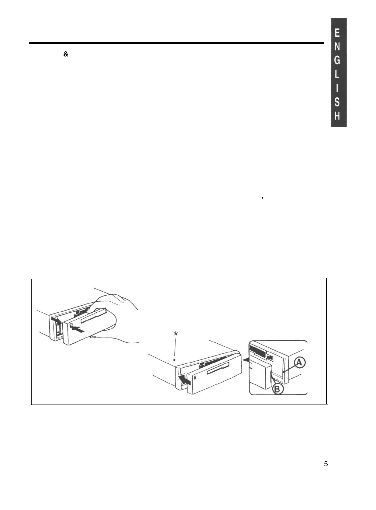
Detachable Face
Detaching
&
Attaching the Face:
The face of this unit can be detached and taken with you to prevent it from being stolen.
Detaching the Face:
Press the REL (Release) Button and detach the face by gently pulling it off as illustrated.
Note: Do not pull it straight out from the chassis. Be sure not to drop the face when detaching it
from the chassis.
Attaching the Face:
Apply the right hand side of the face to the chassis by sliding (part B) of the face to (part A) at the
front of the chassis. Gently push the left side of the face against the front of the chassis until it
snaps into place.
Note: Make sure that the face is inserted right side up. Do not press against the display window.
Do not press hard against the face when attaching it to the chassis, it may be easily attached with
gentle pressure. Do not expose the face to direct sunlight, heat sources such as hot air ducts or
leave it in a humid place. Never leave it on the dash board of a vehicle parked in direct sunlight,
where there may be a considerable rise in temperature inside the vehicle.
Affixing Faceplate For Retail Display:
>
The faceplate can be affixed to the unit’s chassis, which is desirable for a retail display, for
example.
To affix the faceplate:
Insert the black bolt into the hole at the left front of the top of the radio. See* below.
5

Electrical Connections and Installation
@/e?#&*>Q! To avoid the aggravation of costly mistakes and serious damage that could make
you feel this way, please carefully read all of the instructions before you begin. Carefully follow all
instructions. You’ll be glad you did!
GENERAL RECOMMENDATIONS
l If you’re not confident that you can install the unit correctly, have it installed by a qualified
Blaupunkt installation technician.
l Use this unit only with negative ground 12 Volt (11-16 Volt) direct current (DC).
l Be sure to detach the faceplate before you start to connect or install the unit.
l We recommend making and testing all electrical connections before installing the unit. Connect
the leads (wires) according to instructions and diagram below.
IF YOU ARE INSTALLING A COMPATIBLE BLAUPUNKT CD CHANGER
For speaker connection, use the speaker wire harness section that comes with the receiver.
For other connections, use the wire harness sections that come with the CD Changer, not the
receiver. (If you have a CDC-A08 and adapter 7607898093, use the leads on the adapter.)
Note that some of the CD Changer’s wire harness leads have
d,ifferent
colors:
-
In place of yellow lead, use red lead that has yellow BATT. clip for constant power.
-
In place of black lead, use brown lead for ground.
The changer harness or adapter also has gray, blue/white, and orange leads that are
non-functional with this receiver.
ELECTRICAL CONNECTION INSTRUCTIONS
1.
2.
3.
4.
5.
6.
7.
8.
9.
10.
Disconnect the vehicle battery’s negative terminal before making connections.
Connect the speakers and/or external amplifiers (if you have any) following the guidelines in
the SPEAKER CONNECTION section below.
Connect the blue (trigger output) lead to an amplifier’s trigger input terminal and/or antenna
motor trigger input terminal (if you have either or both of these items). The combined total
amperage required for triggering the antenna motor and/or amplifier must not exceed 300
mA.
DO NOT connect the blue lead to the antenna’s and/or amplifier’s power supply input.
Connect the black (power ground) lead to a grounded metal part on the vehicle. We
recommend grounding all audio system black ground leads (head unit, external amplifier, etc.)
to a common grounding point, preferably a non-painted surface under the instrument panel.
Connect the yellow (constant power) input lead to a source of constant battery power,
preferably a terminal to an appropriate slot in the fuse box.
Connect the red (turn-on power) input lead only
afterthe
other leads are connected. Be sure to
connect the red lead to a positive (+) 12 Volt power terminal that is energized only when the
ignition key is set to the on position or accessory position.
Cover the ends of any unused leads with electrical tape. This will prevent them from touching
the vehicle or each other and causing a short-circuit and damage to the radio or vehicle.
Reconnect the vehicle’s battery.
Verify that no fuses have blown.
Plug the harness into the unit.
11. Attach the faceplate and test the unit.
Once the connections have been successfully made, you can begin to mount the unit.
SPEAKER CONNECTIONS
he unit’s Dual-Level Fader allows you to fade between the front and the rear channels using either
the front and/or rear speaker leads and/or the rear preamp outputs, providing you tremendous
flexibility in configuring your speaker arrangement:
l You can connect a speaker (regular, co-axial or tri-axial speakers or component speaker system,
all hereafter referred to simply as “speaker”) to each of the units’ four pairs of speaker leads.
l You can connect the 2 RCA preamp outputs to multiple external amplifiers and power multiple
speakers or speaker systems through the amplifiers. (Blaupunkt amplifiers and speakers
available separately). To add front preamp output, purchase Blaupunkt part 8634494218
(included with changer harness or adapter).
6
 Loading...