

Page 1
EN
Auto Revers
OPERATION MANUAL
Page 2

2
WARNING
!
Follow the user's manual requirements to ensure
durable and trouble-free operation of the unit
Disconnect the unit from power supply prior to any connection,
servicing and repair operations.
Only qualified electricians with a work permit for electrical units up
to 1000 V are allowed for installation and maintenance.
The present user’s manual should be carefully read before
beginning works.
Single-phase power mains must comply with the acting local electrical
norms and standards.
Fixed electrical wiring must be equipped with an automatic
circuit breaker.
The unit must be connected to power mains through a QF automatic
circuit breaker integrated into the fixed wiring system. The gap between
the circuit breaker contacts on all poles must be not less than 3 mm.
Check the unit for any visible damage of the impeller and the casing
before starting installation. The casing internals must be free of any
foreign objects that can damage the impeller blades.
The unit design is constantly being improved, thus some models may be slightly different
from those described in this manual.
Page 3

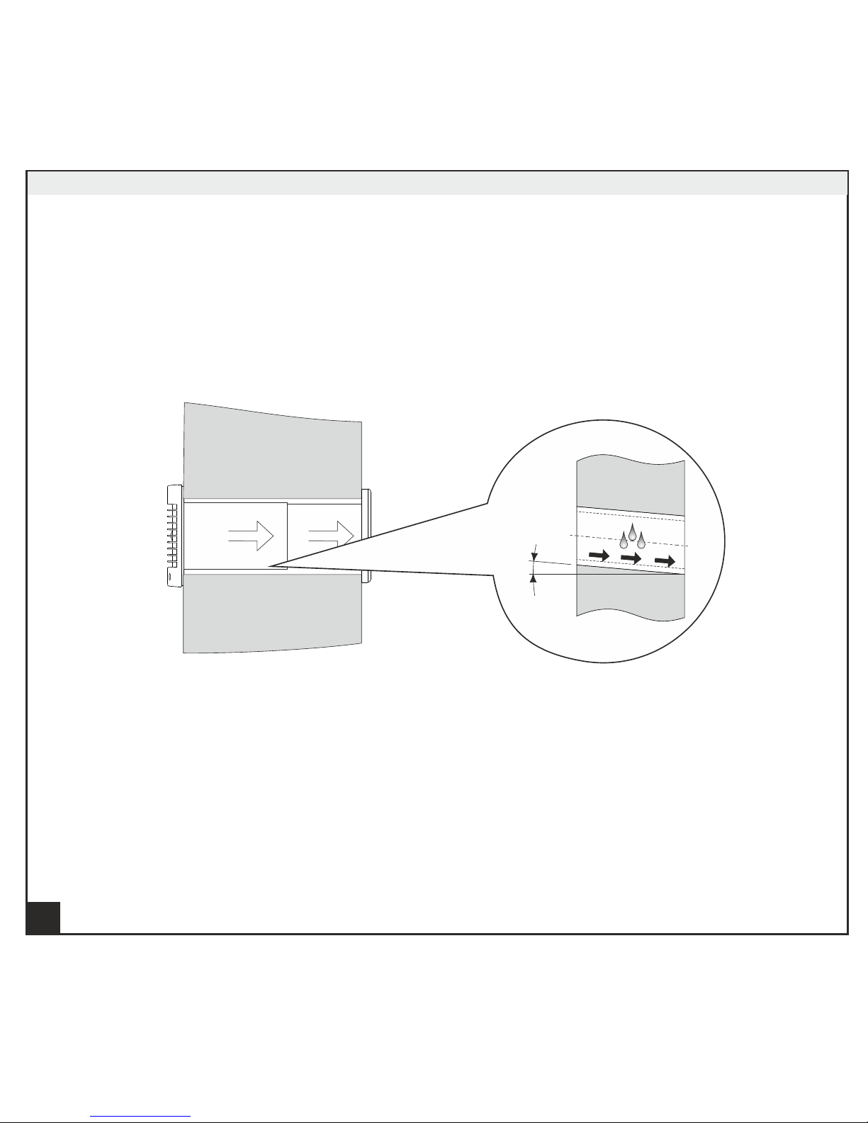
While mounting the unit, avoid compression of the casing!
Deformation of the casing may result in the motor jam and
noisy operation.
Misuse of the unit and any unauthorized modifications are not allowed.
Take steps to prevent ingress of smoke, carbon monoxide, and other
combustion products into the room through open chimney flues
or other fire-protection devices. Sufficient air supply must be provided
for proper combustion and exhaust of gases through the chimney
of fuel burning equipment to prevent back drafting.
Sufficient air supply must be provided for proper combustion and
exhaust of gases through the chimney of fuel burning equipment
to prevent back drafting.
Transported air must not contain any dust or other solid impurities,
sticky substances, or fibrous materials.
3
WARNING
!
Follow the user's manual requirements to ensure
durable and trouble-free operation of the unit
Page 4

Do not use the unit in a hazardous or explosive environment containing
spirits, gasoline, insecticides, etc.
Do not close or block the intake or extract vents in order to ensure
the efficient air flow.
Do not sit on the unit and do not put objects on it.
The timer circuit is under mains voltage.
4
WARNING
!
Follow the user's manual requirements to ensure
durable and trouble-free operation of the unit
Page 5
The unit is allowed to be used by children aged from 8 years old
and above and persons with reduced physical, sensory, or mental
capabilities or no experience and knowledge provided that they
have been given supervision or instruction regarding safe use of
the unit and understand the risks involved.
Do not allow children to play with the unit.
Unit cleaning and maintenance must only be performed by children
under adult supervision.
THE PRODUCT MUST BE DISPOSED SEPARATELY
AT THE END OF ITS SERVICE LIFE. DO NOT DISPOSE
IT AS UNSORTED MUNICIPAL WASTE.
5
WARNING
!
Follow the user's manual requirements to ensure
durable and trouble-free operation of the unit
Page 6

DELIVERY SET
1. Fan:1 piece;
2. Control unit: 1 piece;
3. 5-wire cable: 4 m;
4. Self-tapping screws with expansion anchors: 12 pieces each
5. User's manual;
6. Packing box.
BRIEF DESCRIPTION
The unit is an axial extract fan for extract and/or supply ventilation of small and medium-sized domestic
spaces. The fan is compatible with 150 mm air ducts.
The fan has a white plastic casing and automatic louvres.
The Auto Revers fans are designed for wall-mounted configurations.
OPERATION GUIDELINES
The fan is designed for connection to a 220…240 V/50 Hz single-phase alternating current mains.
о о
The units are suitable for operation at ambient air temperatures from +1 C to +45 C.
The units meet the requirements of IP24 hazardous parts access and water ingress protection standard.
The fan requires no grounding.
The fan is designed for extended periods of continuous operation without disconnection from the
electric mains.
INSTALLATION
The Auto Revers fan installation steps are as follows:
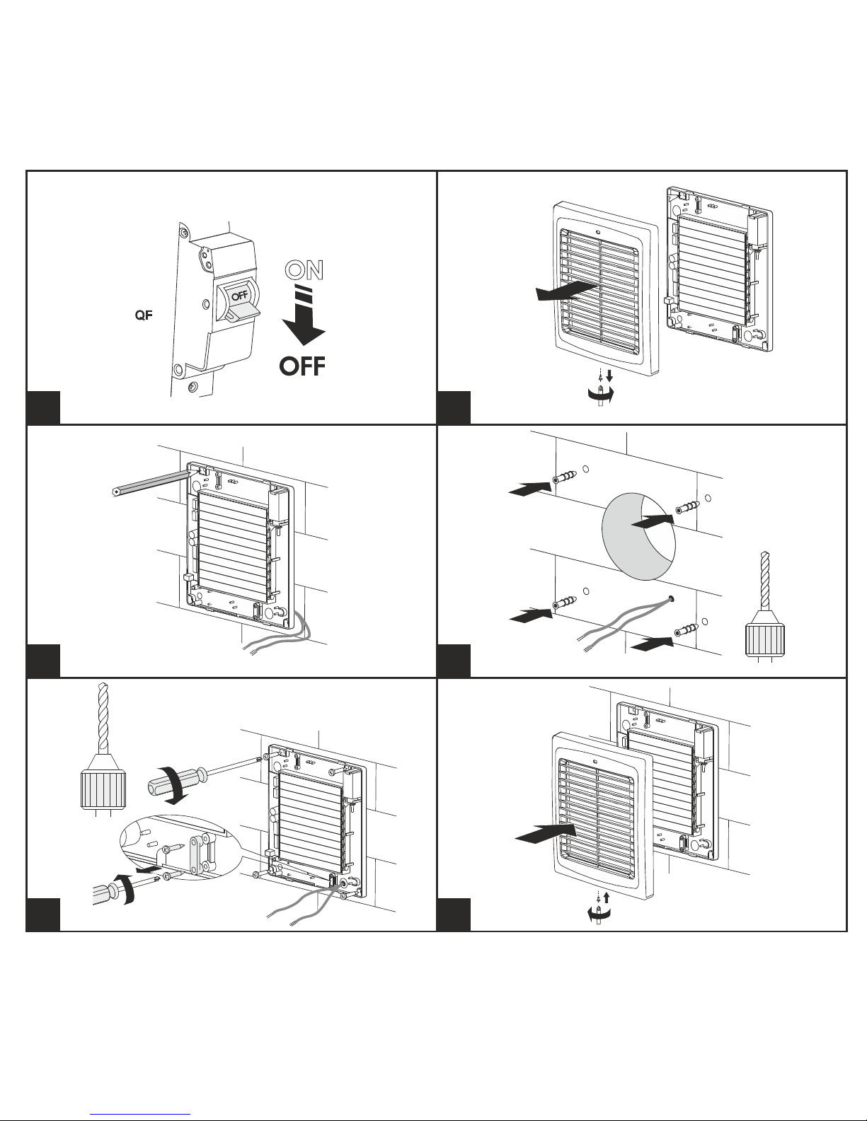
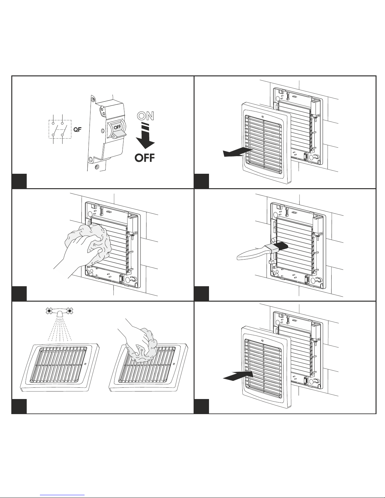
1. Cut off power supply (Fig. 2).
2. Remove the front panel of the fan (Fig. 3).
3. Mark the holes on the wall (Fig. 4).
4. Drill the holes in the wall and insert the expansion anchors (Fig. 5).
5. Remove the self-tapping screws securing the cable clamping plate and remove the plate (Fig. 6). Route the
power and control leads into the casing. Secure the fan casing on the wall with 4 self-tapping screws.
6. Connect the power and control leads to the respective terminal blocks on the control circuit board of the fan
according to Diagram 1. Re-install the cable clamping plate.
7. Install the front panel back in place (Fig. 7).
6
Read the user's manual carefully before proceeding with installation works.
Compliance with the manual requirements ensures reliable operation and long service
life of the unit.
Keep the user's manual available as long as you use the unit.
EN
Page 7

7
EN
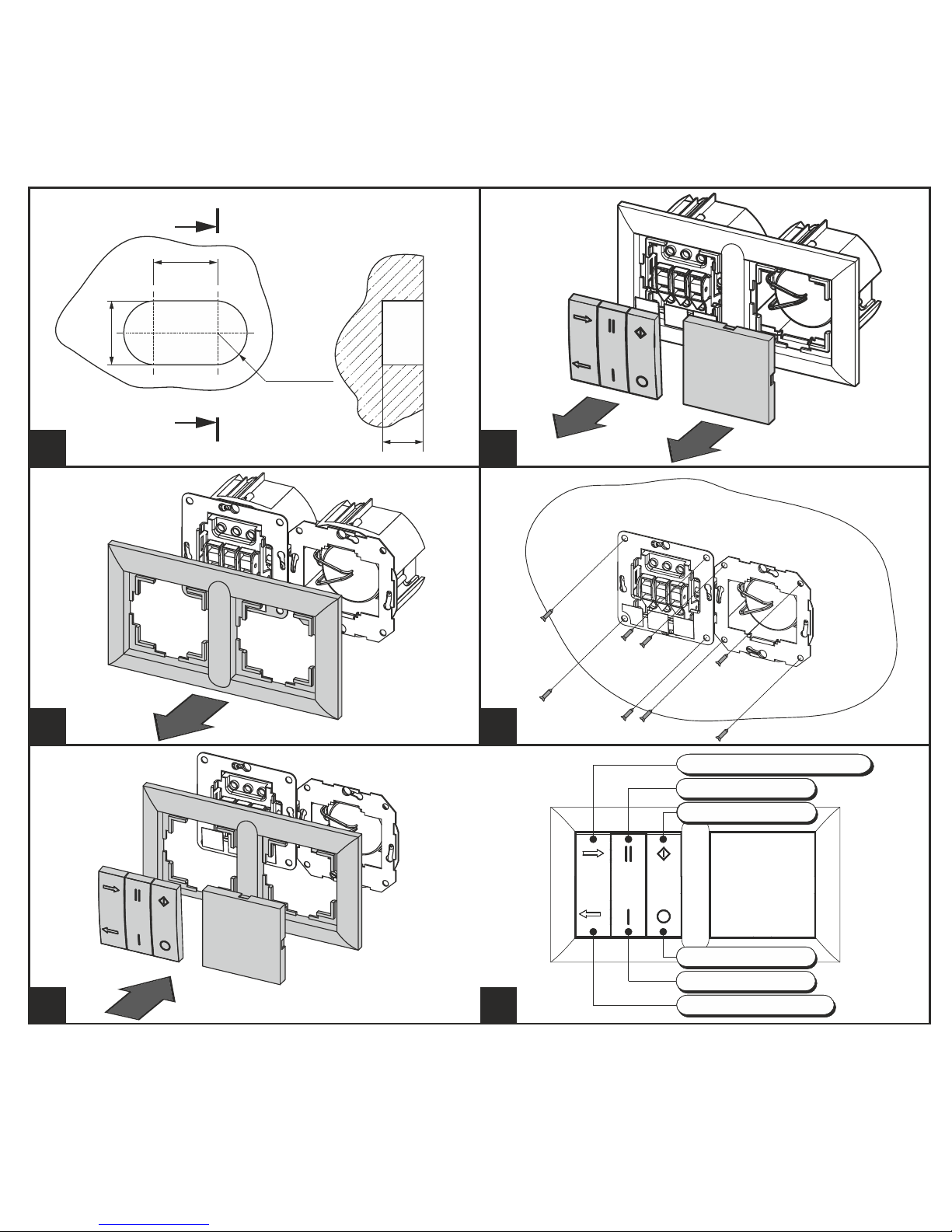
ATTENTION!!! Mind the length of the cable supplied while installing the control unit. If necessary,
a longer cable may be used. The recommended cable type is 5хAWG23 (5x0.25).
Control unit installation:
1. Make a hollow in the wall according to the control unit size (Fig. 8).
2. Remove the power and control unit buttons and plug by prying them gently with a screwdriver (Fig. 9).
3. Remove the power and control unit bezel by releasing the latches (Fig. 10).
4. Connect the power and control cable to the control units according to the wiring diagram 1.
5. Install the power and control unit into the hollow space in the wall (Fig. 11).
6. Install the frame, the buttons and the plug in the reverse order (Fig. 12).
ATTENTION! All the electrical connections to the control unit and the fan must be made using
plug-in terminal blocks. Each terminal block receptacle has a numeric marking with
a corresponding marking on the circuit board for quick and convenient connection. The colour
markings of the wires correspond to the cable supplied with the unit.
Page 8

8
FAN CONTROL
The control unit enables setting one of the four operation modes (Fig. 13):
1. Air extract mode at the low speed
2. Air extract mode at the high speed
3. Air supply mode at the low speed
4. Air supply mode at the high speed
ATTENTION! The potentiometers for speed and time control on the fan circuit board are set in the factory
for correct operation and must not be changed by the user. Any adjustment of the potentiometers is not allowed.
MAINTENANCE
The minimum technical maintenance interval is 6 months.
To clean the unit use a soft cloth and a brush soaked in a detergent water solution (Fig. 14–19).
ATTENTION! Avoid liquid spills on the electric components. Wipe the fan surfaces dry after cleaning.
TRANSPORTATION AND STORAGE REGULATIONS
Transportation with any transportation vehicle in the manufacturer's original package.
Store the fan in the manufacturer's original packing box in a dry ventilated premise at ambient temperatures
from +5 °C up to + 40 °C and relative humidity below 80 %.
Storage environment must not contain aggressive vapours and chemical mixtures provoking corrosion,
insulation and sealing deformation.
EN
Page 9

9
EN
Manufacturer's warranty
The product is in compliance with EU norms and standards on low voltage guidelines and electromagnetic
compatibility. We hereby declare that the product complies with the protection requirements of Electromagnetic
Council Directive 2014/30/EU, Low Voltage Directive 2014/35/EU and CE-marking Directive 93/68/EEC on the
approximation of the laws of the Member States relating to electromagnetic compatibility.
This certificate is issued following the test on the samples of the product referred to above.
Protection degree index according to IP rating against access to hazardous parts and water ingress – IP24. The fan does
not require grounding.
The manufacturer hereby warrants normal operation of the unit for 60 months after the retail sale date provided the
user's observance of the transportation, storage, installation, and operation regulations.
In case of failure due to faulty equipment during the warranty period the consumer has the right to exchange it.
If case of no confirmation of the sale date, the warranty term shall be calculated from the manufacturing date.
The replacement is offered by the Seller.
The MANUFACTURER shall not be liable for any damage resulting from any misuse of or gross mechanic
interference with the unit.
Please follow the applicable instructions.
Page 10
10
1
0.5°...1°
Auto Revers
Page 11
11
2 3
4 5
6 7
Page 12
48
R35
2 radii
70
70
A-A
A
A
12
8
9
10 11
12 13
Exhaust/supply* mode
High speed
Activation
Low speed
Reverse operation
Deactivation
Page 13
13
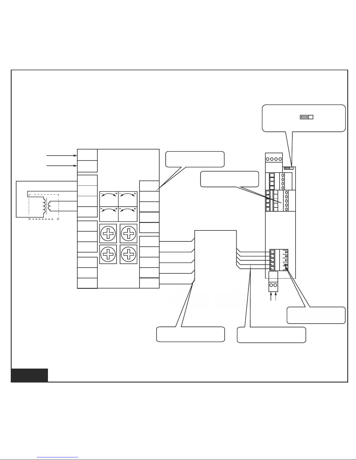
Diagram 1
31
32
L
~ 230 V
T1
Control unit
Fan
JMP1
~ 230 V
N
L
~ 230 V
N
33
35
36
Speed1 Speed2
Speed0 Timer
34
11
12
13
14
15
11
12
13
14
15
40 39 38 37
31 32
36
35
34
33
2
1
3
4
5
1
2
3
4
5
1
2
3
4
5
21
22
23
24
25
1
2
3
4
5
11
12
13
14
15
Marking "11...15" on the
controller socket connector
JMP1
Flow out
(exhaust)
White
Red
Grey
Brown
Yellow
Green
White
Marking "21…25" on the
controller socket connector
Marking "1...5" on the connecting
cable socket connector
Flow in
(supply)
White
Red
Grey
Brown
Yellow
Green
White
Marking "11...15" on the
controller socket connector
Marking "1...5" on the connecting
cable socket connector
Page 14
14
14
15
16
17
18 19
Page 15

15
CERRTIFICATE
OF ACCEPTANCE
WARRANTY
CARD
The fan is recognized as serviceable.
Stamp of the acceptance inspector
Manufacturing date
Sold by
(name of the vendor, stamp of the shop)
Date of sale
Auto Revers 150
Auto Revers
Page 16

www.blaubergventilatoren.de
Auto Revers_EN v.1(4)
 Loading...