


 Loading...

SERVSWITCH™ FAMILY
Welcome to the ServSwitch™ Family!
Thank you for purchasing a BLACK BOX® ServSelect IP! We appreciate your business, and we think you’ll appreciate the many ways that your new ServSelect IP will save you money, time, and effort.
That’s because our ServSwitch family is all about breaking away from the traditional, expensive model of computer management. You know, the one-sizefits-all-even-if-it- doesn’t model that says, “One computer gets one user station, no more, no less.” Why not a single user station (monitor, keyboard, and mouse) for multiple computers—even computers of different platforms? Why not a pair of user stations, each of which can control multiple computers? Why not multiple user stations for the same computer?
With our ServSwitch products, there’s no reason why not. We carry a broad line of robust solutions for all these applications. Do you have just two PCs, and need an economical alternative to keeping two monitors, keyboards, and mice on your desk? Or do you need to share dozens of computers, including a mix of IBM® PC, RS/6000®, Apple® Macintosh®, Sun Microsystems®, and SGI™ compatibles among multiple users with different access levels? Does your switch have to sit solidly on a worktable and use regular everyday cables? Or does it have to be mounted in an equipment rack and use convenient many-to-one cables? No matter how large or small your setup is, no matter how simple or how complex, we’re confident we have a ServSwitch system that’s just right for you.
The ServSwitch™ family from BLACK BOX—the one-stop answer for all your KVM switching needs!
*
This manual will tell you all about your new ServSelect IP, including how to install, operate, and troubleshoot it. For an introduction to the ServSelect IP, see Chapter 2. The ServSelect IP product codes covered in this manual are:
KV120A KV120E KV121A KV212E
This manual also includes information about the ServSelect IP Software and the Server Access Modules, which have their own manuals or installation guides:
KV125A KV126A KV127A KV128A
And this manual also includes information about the ServSwitch™ Multi Z8 switch:
KV158A
1

SERVSELECT™ IP INSTALLER/USER GUIDE
FEDERAL COMMUNICATIONS COMMISSION AND
INDUSTRY CANADA
RADIO-FREQUENCY INTERFERENCE STATEMENTS
This equipment generates, uses, and can radiate radio-frequency energy and if not installed and used properly, that is, in strict accordance with the manufacturer’s instructions, may cause interference to radio communication. It has been tested and found to comply with the limits for a Class A computing device in accordance with the specifications in Subpart B of Part 15 of FCC rules, which are designed to provide reasonable protection against such interference when the equipment is operated in a commercial environment. Operation of this equipment in a residential area is likely to cause interference, in which case the user at his own expense will be required to take whatever measures may be necessary to correct the interference.
Changes or modifications not expressly approved by the party responsible for compliance could void the user’s authority to operate the equipment.
This digital apparatus does not exceed the Class A limits for radio noise emission from digital apparatus set out in the Radio Interference Regulation of Industry Canada.
Le présent appareil numérique n’émet pas de bruits radioélectriques dépassant les limites applicables aux appareils numériques de la classe A prescrites dans le Règlement sur le brouillage radioélectrique publié par Industrie Canada.
EUROPEAN UNION DECLARATION OF CONFORMITY
This equipment has been tested and found to comply with the limits for a class A computing device in accordance with the specifications in the European standard EN55022. These limits are designed to provide reasonable protection against harmful interference. This equipment generates, uses and can radiate radiofrequency energy, and if not installed and used in accordance with the instructions, might cause harmful interference to radio or television reception.
However, there is no guarantee that harmful interference will not occur in a particular installation. If this equipment does cause interference to radio or television reception, which can be determined by turning the equipment on and off, you can correct the interference with one or more of the following measures:
(a)Reorient or relocate the receiving antenna.
(b)Increase the separation between the equipment and the receiver.
(c)Connect the equipment to an outlet on a circuit different from that to which the receiver is connected.
(d)Consult the supplier or an experienced radio/TV technician for help.
2
COMPLIANCE STATEMENTS
Shielded cables must be used with this equipment to maintain compliance with radio frequency energy emission regulations and ensure a suitably high level of immunity to electromagnetic disturbances. This equipment has also been found to comply with European standards EN50082 and EN60950.
Japanese Compliance Statement
Other Agency Approvals
UL 1950, CSA C22. 2 No. 950, IEC 950
Republic of Korea EMI Standard Certificate Number: E-F900-01-2012 (A)
TRADEMARKS USED IN THIS MANUAL
BLACK BOX and the  logo are registered trademarks, and ServSwitch, ServSelect, and ServSelect IP are trademarks, of BLACK BOX Corporation.
Apple, Mac, and Macintosh are registered trademarks of Apple Computer, Inc.
IBM, PS/2, and RS/6000 are registered trademarks of International Business Machines Corporation.
Microsoft, HyperTerminal, Windows, Windows NT, and Windows XP are trademarks or registered trademarks of Microsoft Corporation in the United States and/or other countries.
Sun and Sun Microsystems are registered trademarks of Sun Microsystems, Inc. in the United States and other countries.
UL is a registered trademark of Underwriters Laboratories Inc.
Any other trademarks mentioned in this manual are acknowledged to be the property of the trademark owners.
3

SERVSELECT™ IP INSTALLER/USER GUIDE
Normas Oficiales Mexicanas (NOM)
Electrical Safety Statement
INSTRUCCIONES DE SEGURIDAD
1.Todas las instrucciones de seguridad y operación deberán ser leídas antes de que el aparato eléctrico sea operado.
2.Las instrucciones de seguridad y operación deberán ser guardadas para referencia futura.
3.Todas las advertencias en el aparato eléctrico y en sus instrucciones de operación deben ser respetadas.
4.Todas las instrucciones de operación y uso deben ser seguidas.
5.El aparato eléctrico no deberá ser usado cerca del agua—por ejemplo, cerca de la tina de baño, lavabo, sótano mojado o cerca de una alberca, etc.
6.El aparato eléctrico debe ser usado únicamente con carritos o pedestales que sean recomendados por el fabricante.
7.El aparato eléctrico debe ser montado a la pared o al techo sólo como sea recomendado por el fabricante.
8.Servicio—El usuario no debe intentar dar servicio al equipo eléctrico más allá a lo descrito en las instrucciones de operación. Todo otro servicio deberá ser referido a personal de servicio calificado.
9.El aparato eléctrico debe ser situado de tal manera que su posición no interfiera su uso. La colocación del aparato eléctrico sobre una cama, sofá, alfombra o superficie similar puede bloquea la ventilación, no se debe colocar en libreros o gabinetes que impidan el flujo de aire por los orificios de ventilación.
10.El equipo eléctrico deber ser situado fuera del alcance de fuentes de calor como radiadores, registros de calor, estufas u otros aparatos (incluyendo amplificadores) que producen calor.
11.El aparato eléctrico deberá ser connectado a una fuente de poder sólo del tipo descrito en el instructivo de operación, o como se indique en el aparato.
12.Precaución debe ser tomada de tal manera que la tierra fisica y la polarización del equipo no sea eliminada.
13.Los cables de la fuente de poder deben ser guiados de tal manera que no sean pisados ni pellizcados por objetos colocados sobre o contra ellos, poniendo particular atención a los contactos y receptáculos donde salen del aparato.
14.El equipo eléctrico debe ser limpiado únicamente de acuerdo a las recomendaciones del fabricante.
15.En caso de existir, una antena externa deberá ser localizada lejos de las lineas de energia.
16.El cable de corriente deberá ser desconectado del cuando el equipo no sea usado por un largo periodo de tiempo.
4

NOM STATEMENT
17.Cuidado debe ser tomado de tal manera que objectos liquidos no sean derramados sobre la cubierta u orificios de ventilación.
18.Servicio por personal calificado deberá ser provisto cuando:
A:El cable de poder o el contacto ha sido dañado; u
B:Objectos han caído o líquido ha sido derramado dentro del aparato; o
C:El aparato ha sido expuesto a la lluvia; o
D:El aparato parece no operar normalmente o muestra un cambio en su desempeño; o
E:El aparato ha sido tirado o su cubierta ha sido dañada.
5

SERVSELECT™ IP INSTALLER/USER GUIDE
Contents
1. Specifications . . . . . . . . . . . . . . . . . . . . . . . . . . . . . . . . . . . . . . . . . . . . .9
2. Introduction . . . . . . . . . . . . . . . . . . . . . . . . . . . . . . . . . . . . . . . . . . . . . .10
2.1 Features and Benefits . . . . . . . . . . . . . . . . . . . . . . . . . . . . . . . . . . . . . . . . . . . . .10
2.2 Safety Precautions . . . . . . . . . . . . . . . . . . . . . . . . . . . . . . . . . . . . . . . . . . . . . . . .12
3. Installation . . . . . . . . . . . . . . . . . . . . . . . . . . . . . . . . . . . . . . . . . . . . . . .13
3.1 |
Getting Started . . . . . . . . . . . . . . . . . . . . . . . . . . . . . . . . . . . . . . . . . . . . . . . . . . |
13 |
3.2 |
Rackmounting Your ServSelect IP . . . . . . . . . . . . . . . . . . . . . . . . . . . . . . . . . . |
14 |
3.3 |
Installing the ServSelect IP . . . . . . . . . . . . . . . . . . . . . . . . . . . . . . . . . . . . . . . . . |
15 |
3.4 |
Setting Up Your ServSelect IP and Software . . . . . . . . . . . . . . . . . . . . . . . . . . |
19 |
4. Analog Port Operation . . . . . . . . . . . . . . . . . . . . . . . . . . . . . . . . . . . . .20
4.1 Controlling Your System at the Analog Port . . . . . . . . . . . . . . . . . . . . . . . . . . .20 4.2 Viewing and Selecting Ports and Servers . . . . . . . . . . . . . . . . . . . . . . . . . . . . . .20 4.3 Navigating the OSD . . . . . . . . . . . . . . . . . . . . . . . . . . . . . . . . . . . . . . . . . . . . . .23 4.4 Configuring the OSD . . . . . . . . . . . . . . . . . . . . . . . . . . . . . . . . . . . . . . . . . . . . .24 4.5 Viewing and Disconnecting User Connections . . . . . . . . . . . . . . . . . . . . . . . . .31 4.6 Resetting Your Keyboard and Mouse . . . . . . . . . . . . . . . . . . . . . . . . . . . . . . . . .32 4.7 Displaying Version Information . . . . . . . . . . . . . . . . . . . . . . . . . . . . . . . . . . . . .32 4.8 Scanning Your System . . . . . . . . . . . . . . . . . . . . . . . . . . . . . . . . . . . . . . . . . . . .34 4.9 Broadcasting to Servers . . . . . . . . . . . . . . . . . . . . . . . . . . . . . . . . . . . . . . . . . . .36
5. Terminal Operations . . . . . . . . . . . . . . . . . . . . . . . . . . . . . . . . . . . . . . .38
6. Troubleshooting . . . . . . . . . . . . . . . . . . . . . . . . . . . . . . . . . . . . . . . . . .40
6.1 Calling BLACK BOX . . . . . . . . . . . . . . . . . . . . . . . . . . . . . . . . . . . . . . . . . . . . .40
6.2 Shipping and Packaging . . . . . . . . . . . . . . . . . . . . . . . . . . . . . . . . . . . . . . . . . . .40
Appendix: FLASH Upgrades . . . . . . . . . . . . . . . . . . . . . . . . . . . . . . . . . .41
A.1 Upgrading the ServSelect IP . . . . . . . . . . . . . . . . . . . . . . . . . . . . . . . . . . . . . . .41 A.2 Upgrading the SAM firmware . . . . . . . . . . . . . . . . . . . . . . . . . . . . . . . . . . . . . .42
6

CHAPTER 1: PRODUCT OVERVIEW
1. Specifications
During the course of this product’s lifetime, modifications might be made to its hardware or firmware that could cause these specifications to change without notice.
Agency Approvals
|
EN55022 Class A, EN55024, EN61000-3-3, FCC15 Class A, |
|
VCCI Class A, IEC950, EN60950, UL 1950/60950 third |
|
edition, CSA C22.2 No. 950 |
Server Ports |
|
|
|
Number |
16 |
Interface Type |
Proprietary composite of video, keyboard and mouse (to |
|
SAM adapters) |
Connectors |
RJ-45 |
Sync Types |
Separate horizontal and vertical |
Plug and Play |
DDC2B |
Video Resolution |
Analog Port Maximum 1600 x 1280 @ 75 Hz |
|
Digital Port Maximum 1280 x 1024 @ 75 Hz |
Configuration Port |
|
Number |
1 |
Interface Type |
Serial RS-232, DTE |
Connector |
DB9 Female |
Network Connection |
|
Number |
1 |
Interface Type |
Ethernet: IEEE 802.3, 10BASE-T, |
|
Fast Ethernet: IEEE 802.3U, 100BASE-T |
Connector |
RJ-45 |
Analog Port |
|
Number |
1 |
Interface Types |
PS/2 and VGA |
Connectors |
(2) 6 pin MiniDIN, (1) HD15 |
Other Characteristics |
|
Heat Dissipation |
92 BTU/Hr |
Airflow |
8 cfm |
Temperature |
10º to 50º Celsius (50º to 122º Fahrenheit) operating |
|
-20º to 60º Celsius (-4º to 140º Fahrenheit) nonoperating |
Humidity |
20 to 80% noncondensing operating |
|
5 to 95% noncondensing nonoperating |
Power |
100 to 240 VAC, 50 to 60 Hz (autosensing), 40 W maximum |
AC-input current rating |
1A |
AC-input cable |
18 AWG three-wire cable, with a three lead IEC-320 |
|
receptacle on the power supply end and a country or region |
|
dependent plug on the power resource end |
Power Consumption |
25 W |
Size (HxWxD) |
4.45 x 43.18 x 27.94 cm 1U form factor |
|
(1.75 x 17.00 x 11.00 in) |
Weight |
3.6 kg (8 lb) without cables |
7
SERVSELECT™ IP INSTALLER/USER GUIDE
2.Introduction
2.1Features and Benefits
The BLACK BOX® ServSelect™ IP switches combine analog and digital technology to provide flexible, centralized control of data center servers. This solution delivers secure digital access and flexible server management from anywhere at any time.
NOTE:
Throughout the text, the word “appliance” is used generically to describe the ServSelect IP switch.
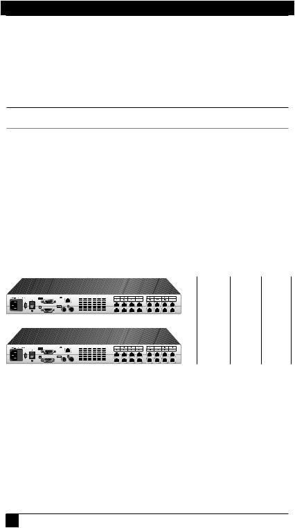
The ServSelect IP consists of a rackmountable keyboard, video and mouse (KVM) switch configurable for analog or digital connectivity. Each ServSelect IP has
16 Analog Rack Interface (ARI) ports for connecting devices and operates over standard LAN connections. Access servers across a 100BASE-T Ethernet connection or directly through an analog port on the ServSelect IP for analog KVM connectivity and administration. Video resolutions through the analog port can be up to 1600 x 1280 with an end-to-end cable length of up to 15 meters (50 feet). Digital users can achieve video resolution of up to 1280 x 1024 with a cable length of up to 10 meters (32 feet) between the ServSelect IP and the server.
Number
of Digital Analog servers* users user
ServSelect IP - KV120
128 1 1
ServSelect IP - KV121
128 |
2 |
1 |
*Maximum number of servers with a fully configured KV158Aswitch attached to each of the 16ARI ports.
Figure 2-1. ServSelect IP Model Comparison
Server Access Modules
The Server Access Module (SAM) with CAT5 design dramatically reduces cable clutter, while providing optimal digital display resolution and video settings. The built-in memory of the SAM simplifies configuration by assigning and retaining unique server names or Electronic ID (EID) numbers for each attached server. This integrated intelligence enhances security and prevents unauthorized access to a server through cable manipulation. The SAM is powered directly from the server and provides Keep Alive functionality even if the ServSelect IP is not powered.
8
CHAPTER 2: INTRODUCTION
Access via network connection
No special software or drivers are required on the attached computers. Digital users access the ServSelect IP and all attached systems via Ethernet from a PC running ServSelect IP Software. This software resides on the user’s PC only. User PCs can be located anywhere a valid network connection exists. The ServSelect IP can be configured on a separate network from your data network, allowing access to your servers even if your applications network is down.
Point and click control with ServSelect IP Software
The ServSelect IP Software is a cross-platform management application that allows you to view and control the ServSelect IP and all attached servers. The ServSelect IP Software provides secure authentication, data transfers and username/password storage. By utilizing a browser interface for navigation with an intuitive split-screen interface, this software provides you with a single point of access for your entire system. From here, you can manage the ServSelect IP, install a new ServSelect IP or launch a video session to a system server. Multiple servers can be accessed by one user; each additional computer’s video will appear in a separate program window.
|
SAM |
Switch |
|
Adapter |
|
|
|
Rack of |
SAM |
Switch |
Servers |
|
||
Adapter |
|
|
|
|
|
|
Rack of |
|
|
Servers |
|
|
|
Critical Server |
|
|
ServSelect IP |
TCP/IP
Analog Connection |
TCP/IP |
|
IP Connections
Figure 2-2. Example ServSelect IP Configuration
9
SERVSELECT™ IP INSTALLER/USER GUIDE
2.2 Safety Precautions
To avoid potential video and/or keyboard problems when using these products:
•If the building has 3-phase AC power, ensure that the computer and monitor are on the same phase. For best results, they should be on the same circuit.
•Use only BLACK BOX-supplied cable to connect computers and KVM switches.
To avoid potentially fatal shock hazard and possible damage to equipment, please observe the following precautions:
•Do not use a 2-wire extension cord in any BLACK BOX product configuration.
•Test AC outlets at the computer and monitor for proper polarity and grounding.
•Use only with grounded outlets at both the computer and monitor. When using a backup power supply (UPS), power the computer, the monitor and the appliance off the supply.
NOTE:
The AC inlet is the main disconnect.
Rackmount safety considerations
•Elevated Ambient Temperature: If the equipment is installed in a closed rack assembly, the operation temperature of the rack environment may be greater than room ambient. Use care not to exceed the rated maximum ambient temperature of the equipment.
•ReducedAir Flow: Installation of the equipment in a rack should be such that the amount of airflow required for safe operation of the equipment is not compromised.
•Mechanical Loading: Mounting of the equipment in the rack should be such that a hazardous condition is not achieved due to uneven mechanical loading.
•Circuit Overloading: Consideration should be given to the connection of the equipment to the supply circuit and the effect that overloading of circuits might have on overcurrent protection and supply wiring. Consider equipment nameplate ratings for maximum current.
•Reliable Earthing: Reliable earthing of rackmounted equipment should be maintained. Pay particular attention to supply connections other than direct connections to the branch circuit (for example, use of power strips).
10

CHAPTER 3: INSTALLATION
3. Installation
The ServSelect® IP system requires that the ServSelect IP Software be installed prior to use. ServSelect IP Software allows you to view and control a server attached to the appliance system, configure and maintain the system and prevent unauthorized access to the appliance via IP connection.
NOTE:
The analog port does not require the ServSelect IP Software for operation. The analog port uses the On-Screen Display (OSD). For more information, see Chapter 4.
The ServSelect IP system uses Ethernet networking infrastructure and TCP/IP protocol to transmit keyboard, video and mouse information between operators and connected computers. Although 10BASE-T Ethernet may be used, a dedicated, switched 100BASE-T network provides improved performance.
3.1 Getting Started
Before installing your ServSelect IP appliance, refer to the following list to ensure you have all items that shipped with the appliance as well as other items necessary for proper installation. The KV120/121A models ship with power input cords appropriate for North America. The KV120/121E models ship with power input cords appropriate for Europe.
Supplied with the ServSelect IP
•ServSelect IP unit
•Power cord
•Rackmounting kit
•One straight-through null modem serial cable
•ServSelect IP Installer/User Guide
•ServSelect IP Software Installer/User Guide
•ServSelect IP Quick Installation Guide
Additional items needed
•One SAM per attached server or switch
Setting up your network
The ServSelect IP system uses IP addresses to uniquely identify the appliances and the computers running ServSelect IP Software. The ServSelect IP appliance supports both BootP (a subset of DHCP) and static IP addressing. BLACK BOX®
11
SERVSELECT™ IP INSTALLER/USER GUIDE
recommends that IP addresses be reserved for each unit and that they remain static while the appliances are connected to the network.
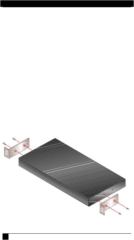
3.2 Rackmounting Your ServSelect IP
Your ServSelect IP appliance ships with rackmounting brackets for easy integration into your rack. Before installing the appliance and other components in the rack cabinet, stabilize the rack in a permanent location. Install your equipment starting at the bottom of the rack cabinet, then work to the top. Avoid uneven loading or overloading of rack cabinets.
To install the 1U switch mounting bracket:
1.Line up the holes in the “long side” of the kit’s side brackets with the screw holes in the switch.
2.With a Phillips screwdriver, fasten the mounting brackets to the switch using two 8/32" x 1/2" pan head screws on each side.
3.Attach the four cage nuts or clip nuts to the rackmounting flange of the rack cabinet so that the nut is positioned on the inside of the rack.
4.Mount the switch assembly to the rack cabinet by matching the holes in the “short side” of each bracket to an appropriate set of matching holes on your rack cabinet. Next, insert the combination hex head screws through the slots in the bracket and the holes in the mounting rail, then into the cage nuts or clip nuts.
Figure 3-1. ServSelect IP Horizontal Installation
12
CHAPTER 3: INSTALLATION
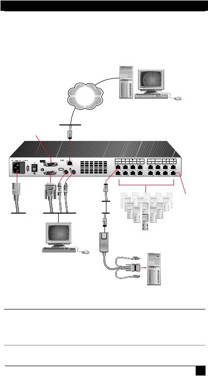
3.3 Installing the ServSelect IP
Figure 3.2 illustrates one possible configuration for your ServSelect IP appliance. Follow the detailed set of procedures following Figure 3.2 to successfully install your appliance.
Network
Digital User
one user for the KV120A or two users for the KV121A
Configuration Port for updating firmware
ServSelect IP Appliance
ARI
Port
Power Cord
Servers 2-16
Local Analog
User
SAM Adaptor
PS/2, USB and Sun adaptors are
available
Server 1
Figure 3-2. Basic ServSelect IP Configuration
CAUTION:
To reduce the risk of electric shock or damage to your equipment-
-Do not disable the power cord grounding plug. The grounding plug is an important safety feature.
-Plug the power cord into a grounded (earthed) outlet that is easily accessible at all times.
-Disconnect the power from the unit by unplugging the power cord from either the electrical outlet or the unit.
13
Loading...