


RIM OEM Radio Modem for GSM/ GPRS Wireless Networks
RIM 1902G™ and RIM 1802G™
Getting Started Guide
Version 1.2
RIM OEM Radio Modem for GSM/GPRS Wireless Networks
Version 1.2
Getting Started Guide
Last revised: 08 August 2003
Part number: PDF-05732-004
MAT-06067-001
The information in this document is RIM confidential and is for internal distribution only.
© 2003 Research In Motion Limited. All Rights Reserved. The BlackBerry and RIM families of related marks, images and symbols are the exclusive properties of Research In Motion Limited. RIM, Research In Motion, ‘Always On, Always Connected’, the “envelope in motion” symbol and the BlackBerry logo are registered with the U.S. Patent and Trademark Office and may be pending or registered in other countries. All other brands, product names, company names, trademarks and service marks are the properties of their respective owners.
The handheld and/or associated software are protected by copyright, international treaties and various patents, including one or more of the following U.S. patents: 6,278,442; 6,271,605; 6,219,694; 6,075,470; 6,073,318; D445,428; D433,460; D416,256. Other patents are registered or pending in various countries around the world. Visit www.rim.net/patents.shtml for a current listing of applicable patents.
While every effort has been made to achieve technical accuracy, information in this document is subject to change without notice and does not represent a commitment on the part of Research In Motion Limited, or any of its subsidiaries, affiliates, agents, licensors, or resellers. There are no warranties, express or implied, with respect to the content of this document.
Research In Motion Limited
295 Phillip Street
Waterloo, ON N2L 3W8
Canada
Research In Motion UK Limited
Centrum House, 36 Station Road
Egham, Surrey TW20 9LF
United Kingdom
Published in Canada
Contents |
|
|
|
About this guide.............................................................................................. |
5 |
|
Related resources................................................................................................ |
5 |
|
Support................................................................................................................. |
5 |
CHAPTER 1 |
Setting up the Interface and Test Board ....................................................... |
7 |
|
Setup overview ................................................................................................... |
8 |
|
Connecting the SIM card ................................................................................... |
9 |
|
Connecting the radio modem ......................................................................... |
10 |
|
Connecting to the computer ........................................................................... |
10 |
|
Inserting the SIM card into the SIM card holder ......................................... |
11 |
|
Connecting the antenna to the radio modem............................................... |
12 |
|
Connecting to an AC outlet............................................................................. |
12 |
|
Turning on the system ..................................................................................... |
12 |
|
Connecting the headset ................................................................................... |
12 |
CHAPTER 2 |
Connecting the radio modem to a computer.............................................. |
13 |
|
Required information....................................................................................... |
14 |
|
Connecting with Windows 2000 .................................................................... |
14 |
|
Connecting with Windows 95/98 ................................................................... |
22 |
|
Setting up HyperTerminal .............................................................................. |
26 |
Getting Started Guide |
3 |
4 |
RIM OEM Radio Modem for GSM/GPRS Wireless Networks |

About this guide
This guide provides information on the following topics:
•setting up the Interface and Test Board
•connecting the radio modem to your computer
This guide is intended to help you start testing the RIM 1902G™ or RIM 1802G™ radio modems.
Related resources
Refer to the following documentation, which is included in the Integrator’s Kit:
•Integrator Guide
The Integrator Guide explains how to integrate the RIM 1802G or RIM 1902G into a variety of devices. This guide explains integration steps, provides an overview of the test board, mounting requirements, power (battery) requirements, and antenna selection and placement.
•AT Command Reference Guide
The AT Command Reference Guide lists the AT commands that apply to the RIM 1902G and RIM 1802G.
Support
To discuss the technical integration of the radio modem, contact RIM at
oemsupport@rim.net.
About this guide
6 |
RIM OEM Radio Modem for GSM/GPRS Wireless Networks |

Chapter 1
Setting up the Interface and Test Board
This guide provides information on the following topics:
•Setup overview
•Connecting the SIM card
•Connecting the radio modem
•Connecting to the computer
•Inserting the SIM card into the SIM card holder
•Connecting the antenna to the radio modem
•Connecting to an AC outlet
•Turning on the transceiver
•Connecting the headset

Chapter 1: Setting up the Interface and Test Board
Setup overview
To set up the Interface and Test Board, perform these tasks:
1.Insert the SIM card into the SIM card holder on the Interface and Test Board (off-board SIM configuration) or directly onto the radio modem (on-board SIM configuration).
2.Connect the radio modem to the Interface and Test Board using the 22-pin connector cable.
3.Connect the Interface and Test Board to the computer using a standard RS-232 cable.
4.Connect the antenna to the radio modem.
5.Connect the Interface and Test Board to an AC outlet.
6.Turn the transceiver on/off switch to the “on” position
7.Connect the headset.
The following diagram illustrates the Interface and Test Board and major components.
power jack |
|
|
|
|
|
|
|
microphone/ |
|
|
|
||||||||
|
|
|
|
|
|
|
|
|
speaker jacks |
|
|
|
|
|
Mic Spkr |
||||
RS-232 |
|
|
|
|
|
|
|
transceiver |
|
|
|
|
|
|
|
||||
interface |
|
|
|
|
|
|
on/off switch |
||
22-pin |
|
|
|
|
|
|
|
|
|
|
|
|
|
|
|
|
|
|
|
connector |
|
|
|
|
|
|
|
|
|
cable |
|
|
|
|
|
|
|
|
|
test point
LED indicator
GPRS
Radio Modem
Interface and Test Board (on-board SIM configuration) – top view
8 |
RIM OEM Radio Modem for GSM/GPRS Wireless Networks |
Connecting the SIM card
Connecting the SIM card
Note: This task only applies to the off-board SIM configuration.
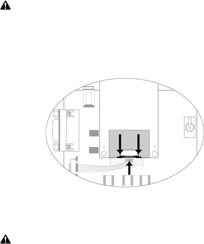
The 6-pin flat SIM interface cable carries the data and power between the Interface and Test Board SIM slot and the radio modem.
1.Remove the radio modem from the Interface and Test Board: unfasten the nuts and lift the radio modem up and away from the Interface and Test Board.
2.On the underside of the modem, on the connector, push the two black tabs up from the connector to widen the opening.
Underside of radio modem showing the 6-pin connector
3.With the blue side facing the Interface and Test Board, insert the end of the cable 6-pin cable into the connector. Verify that the side with the bare pins is in direct contact with the pin side of the connector.
Note: Do not force the cable into the connector.
4.Push the black tabs down toward the connector to secure the cable.
5.Repeat steps 2 through 4 to connect the 6-pin connector to the Interface and Test Board.
6.Re-attach the radio modem to the Interface and Test Board.
Getting Started Guide |
9 |
 Loading...