


Black Box VX-HDMI-POE-MRX, VX-HDMI-POE-VTX, VX-HDMI-POE-VRX, VX-HDMI-POE-MTX, VX-HDMI-POE-URX User Manual
...VX-HDMI-POE-MTX VX-HDMI-POE-UTX VX-HDMI-POE-VTX.
VX-HDMI-POE-MRX VX-HDMI-POE-URX VX-HDMI-POE-VRX
MediaCento™ IPX with PoE
Extend audio and video signals via an existing LAN.
Distribute HDMI video to an unlimited number of displays using IP multicast, or make eye-catching video walls of up to 8 x 8 displays.
Customer Order toll-free in the U.S.: Call 877-877-BBOX (outside U.S. Support call 724-746-5500) • FREE technical support 24 hours a day, 7 days
Information a week: Call 724-746-5500 or fax 724-746-0746 • Mailing address: Black Box Corporation, 1000 Park Drive, Lawrence, PA 15055-1018 Web site: www.blackbox.com • E-mail: info@blackbox.com

Trademarks Used in this Manual
Trademarks Used in this Manual
Black Box and the Double Diamond logo are registered trademarks, and MediaCento is a trademark, of BB Technologies, Inc.
Bonjour and Apple are registered trademarks of Apple, Inc. Windows is a registered trademark of Microsoft Corporation. UL is a registered trademark of Underwriters’ Laboratories.
Any other trademarks mentioned in this manual are acknowledged to be the property of the trademark owners.
Page 2 |
724-746-5500 | blackbox.com |

FCC RFI Statement
FEDERAL COMMUNICATIONS COMMISSION AND INDUSTRY CANADA RADIO FREQUENCY INTERFERENCE STATEMENTS
This equipment generates, uses, and can radiate radio-frequency energy, and if not installed and used properly, that is, in strict accordance with the manufacturer’s instructions, may cause interference to radio communication. It has been tested and found to comply with the limits for a Class A computing device in accordance with the specifications in Subpart B of Part 15 of FCC rules, which are designed
to provide reasonable protection against such interference when the equipment is operated in a commercial environment. Operation of this equipment in a residential area is likely to cause interference, in which case the user at his own expense will be required to take whatever measures may be necessary to correct the interference.
Changes or modifications not expressly approved by the party responsible for compliance could void the user’s authority to operate the equipment.
This digital apparatus does not exceed the Class A limits for radio noise emission from digital apparatus set out in the Radio Interference Regulation of Industry Canada.
Le présent appareil numérique n’émet pas de bruits radioélectriques dépassant les limites applicables aux appareils numériques de classe A prescrites dans le Règlement sur le brouillage radioélectrique publié par Industrie Canada.
Normas Oficiales Mexicanas (NOM)Electrical Safety Statement
INSTRUCCIONES DE SEGURIDAD
1.Todas las instrucciones de seguridad y operación deberán ser leídas antes de que el aparato eléctrico sea operado.
2.Las instrucciones de seguridad y operación deberán ser guardadas para referencia futura.
3.Todas las advertencias en el aparato eléctrico y en sus instrucciones de operación deben ser respetadas.
724-746-5500 | blackbox.com |
Page 3 |

NOM Statement
4.Todas las instrucciones de operación y uso deben ser seguidas.
5.El aparato eléctrico no deberá ser usado cerca del agua—por ejemplo, cerca de la tina de baño, lavabo, sótano mojado o cerca de una alberca, etc.
6.El aparato eléctrico debe ser usado únicamente con carritos o pedestales que sean recomendados por el fabricante.
7.El aparato eléctrico debe ser montado a la pared o al techo sólo como sea recomendado por el fabricante.
8.Servicio—El usuario no debe intentar dar servicio al equipo eléctrico más allá a lo descrito en las instrucciones de operación. Todo otro servicio deberá ser referido a personal de servicio calificado.
9.El aparato eléctrico debe ser situado de tal manera que su posición no interfiera su uso. La colocación del aparato eléctrico sobre una cama, sofá, alfombra o superficie similar puede bloquea la ventilación, no se debe colocar en libreros o gabinetes que impidan el flujo de aire por los orificios de ventilación.
10.El equipo eléctrico deber ser situado fuera del alcance de fuentes de calor como radiadores, registros de calor, estufas u otros aparatos (incluyendo amplificadores) que producen calor.
11.El aparato eléctrico deberá ser connectado a una fuente de poder sólo del tipo descrito en el instructivo de operación, o como se indique en el aparato.
12.Precaución debe ser tomada de tal manera que la tierra fisica y la polarización del equipo no sea eliminada.
13.Los cables de la fuente de poder deben ser guiados de tal manera que no sean pisados ni pellizcados por objetos colocados sobre o contra ellos, poniendo particular atención a los contactos y receptáculos donde salen del aparato.
14.El equipo eléctrico debe ser limpiado únicamente de acuerdo a las recomendaciones del fabricante.
15.En caso de existir, una antena externa deberá ser localizada lejos de las lineas de energia.
Page 4 |
724-746-5500 | blackbox.com |

NOM Statement
16.El cable de corriente deberá ser desconectado del cuando el equipo no sea usado por un largo periodo de tiempo.
17.Cuidado debe ser tomado de tal manera que objectos liquidos no sean derramados sobre la cubierta u orificios de ventilación.
18.Servicio por personal calificado deberá ser provisto cuando:
A:El cable de poder o el contacto ha sido dañado; u
B:Objectos han caído o líquido ha sido derramado dentro del aparato; o
C:El aparato ha sido expuesto a la lluvia; o
D:El aparato parece no operar normalmente o muestra un cambio en su desempeño; o
E:El aparato ha sido tirado o su cubierta ha sido dañada.
724-746-5500 | blackbox.com |
Page 5 |

Table of Contents
Table of Contents
1. |
Specifications................................................................................................... |
8 |
||
2. |
Overview |
................................................................................................. |
10 |
|
|
2.1 |
Introduction.......................................................................................... |
10 |
|
|
2.2 |
Available Models................................................................................... |
10 |
|
|
2.3 |
Features................................................................................................. |
10 |
|
|
|
2.3.1 Multicast, Unicast, and Video Wall Transmitters |
|
|
|
|
|
and Receivers........................................................................... |
10 |
|
|
2.3.2 Multicast Transmitter and Receiver Exclusive Functions.......... |
11 |
|
|
2.4 |
What’s Included.................................................................................... |
11 |
|
|
2.5 Additional Items You Will Need............................................................ |
12 |
||
|
2.6 |
Hardware Description........................................................................... |
12 |
|
|
|
2.6.1 |
Transmitters.............................................................................. |
12 |
|
|
2.6.2 |
Receivers................................................................................... |
15 |
|
|
2.6.3 |
Indicators.................................................................................. |
18 |
|
|
2.6.4 Function Buttons (F1 and F2)................................................... |
18 |
|
|
|
2.6.5 |
EDID Copy................................................................................ |
19 |
3. |
Installation |
................................................................................................. |
20 |
|
4. |
Configuration................................................................................................. |
22 |
||
|
4.1 |
Basic Configuration............................................................................... |
22 |
|
|
4.2 |
Advanced Configuration....................................................................... |
22 |
|
|
|
4.2.1 |
Accessing through Serial.......................................................... |
23 |
|
|
4.2.2 |
Accessing through Telnet......................................................... |
23 |
5. |
Advanced Commands................................................................................... |
25 |
||
|
5.1 |
Advanced IP Commands....................................................................... |
26 |
|
|
5.2 |
Advanced Multicast IP Configuration................................................... |
27 |
|
|
|
5.2.1 |
Transmitter............................................................................... |
29 |
|
|
5.2.2 |
Receiver.................................................................................... |
29 |
|
5.3 |
Serial Extension..................................................................................... |
29 |
|
|
5.4 |
Telnet Extension.................................................................................... |
30 |
|
6 Accessing the Web Interface......................................................................... |
33 |
|||
|
6.1 Accessing the Transmitter without an IP Address................................ |
33 |
||
|
6.2 Accessing the Web Interface for a Transmitter |
|
||
|
|
or Receiver with an IP Address............................................................. |
35 |
|
Page 6 |
724-746-5500 | blackbox.com |

|
|
|
Table of Contents |
|
|
|
|
7. |
Video Wall Features....................................................................................... |
36 |
|
8. |
Troubleshooting............................................................................................. |
43 |
|
|
8.1 |
Problems/Solutions............................................................................... |
43 |
|
8.2 |
Contacting Black Box............................................................................ |
43 |
|
8.3 |
Shipping and Packaging........................................................................ |
44 |
Appendix: Connector Pinouts............................................................................... |
45 |
||
724-746-5500 | blackbox.com |
Page 7 |

Chapter 1: Specifications
1. Specifications
Technical Specifications
Approvals |
FCC, TUV, CE, UL®, CSA, RoHS, WEEE |
Bandwidth |
120 Mbps maximum |
|
|
Default IP Address |
169.254.x.x (with no DHCP address) |
|
NOTE: To find the IP address of any receiver, simply |
|
connect to monitor and power up to get IP |
|
address. To find the IP address of any other |
|
receiver or transmitter, use Telnet to connect to |
|
any device in the system and use a “node_list” |
|
command or connect with the serial interface. |
|
|
Distance |
From CPU to TX: 16 ft. (5 m) maximum, HDMI; |
|
Between TX and RX: 328 ft. (100 m)* maximum |
|
*NOTE: Use a network switch to get greater distances. |
|
|
Efficiency Level |
Level IV |
|
|
Heat Dissipation |
3.41 BTU/hr. |
|
|
HDCP |
Supported |
|
|
Latency |
2 frames (33 ms) maximum |
|
|
Leads Supported |
HDMI video and RS-232 |
|
|
MTBF |
90,000 hours |
|
|
User Controls |
(1) 16-position rotary selection switch, |
|
(2) Function buttons: (1) F1, (1) F2 |
|
|
Page 8 |
724-746-5500 | blackbox.com |

|
|
Chapter 1: Specifications |
|
|
|
Technical Specifications (continued) |
||
|
|
|
Connectors |
(1) |
HDMI female, |
|
(1) |
RJ-45 interconnect/LAN connection, |
|
(1) |
2.1-mm barrel connector for power, |
|
(2) RJ-12 6P6C† |
|
|
†NOTE: Only 4 center pins are used at this time. |
|
|
|
|
Indicators |
(1) |
LED for Link and Power; |
|
(1) |
LED for Network Activity |
|
|
|
Environmental |
Temperature Tolerance: |
|
|
|
Operating: 32 to 104° F (0 to 40° C); |
|
|
Storage: -4 to +140° F (-20 to +60° C) |
|
Humidity Tolerance: Operating: 80%, noncondensing; |
|
|
Altitude: 10,000 ft. (3048 m) maximum |
|
|
|
|
Power |
Input: 100–240 VAC, 50/60 Hz, 0.6 A; |
|
|
Output: 12 VDC; |
|
|
Consumption: 13.5 W; |
|
|
Power Supply Cord Length: 6 ft. (1.8 m) |
|
|
|
|
Power over Ethernet |
Complies with IEEE 802.3af standard; |
|
(PoE) |
Power: Nominal Input: 48 VDC; |
|
|
Input Range: 36–57 VDC |
|
|
|
|
Size |
0.98"H x 3.77"W x 5.11"D (2.5 x 9.6 x 12.9 cm) |
|
|
|
|
Weight |
1.1 lb. (0.5 kg) |
|
|
|
|
724-746-5500 | blackbox.com |
Page 9 |

Chapter 2: Overview
2. Overview
2.1 Introduction
The MediaCento IPX with PoE is a perfect solution for audio and video signal extension via an existing Local Area Network (LAN) system. With multicast technology, one local unit can drive multiple remote units with no extra network load. There are 16 selectable channels that can be used to transmit to multiple receivers. In a network that supports IGMP (Layer 2 or Layer 3 switches), each channel can connect to unlimited displays in video wall applications and unlimited displays in a multicast application using a standard IT Ethernet structure on a LAN system.
The MediaCento IPX with PoE supports Full HD 1080p, is HDCP compliant, is Blu-ray ready, and supports Power over Ethernet (PoE). It can handle applications that require greater distance, high speed transmission, real-time high video resolution, security, and noise immunity. It is ideal for situations that need live presentation, such as public broadcasting, education centers, boardrooms, etc.
2.2 Available Models
Three transmitter/receiver pairs are available, and they are ordered separately by part number. Choose from:
•MediaCento IPX Multicast Transmitter (VX-HDMI-POE-MTX) and MediaCento IPX Multicast Receiver (VX-HDMI-POE-MRX)
•MediaCento IPX Unicast Transmitter (VX-HDMI-POE-UTX) and MediaCento IPX Unicast Receiver (VX-HDMI-POE-URX)
•MediaCento IPX Video Wall Transmitter (VX-HDMI-POE-VTX) and MediaCento IPX Video Wall Receiver (VX-HDMI-POE-VRX)
2.3 Features
2.3.1 Multicast, Unicast, and Video Wall Transmitters and
Receivers
•Extend high definition video signal over LAN (dependent on network performance).
•Power over Ethernet:
-Fully support IEEE Std. 802.3af-2003
-Input Voltage Range 36V to 57V
•Choose from 16 selections on the DIP rotary switch for pairing.
Page 10 |
724-746-5500 | blackbox.com |
Chapter 2: Overview
•Provide automatic EDID configuration.
•Use well-developed Ethernet technology and TCP/IP communication protocol.
•Transmitters and Receivers are HDCP-compliant and Blu-ray ready.
•HDTV compatible; support 1080p, 1080i, 720p, 720i.
•Compatible with popular screen resolutions: XGA, SXGA, UXGA, WSXGA.
2.3.2 Multicast Transmitter and Receiver Exclusive Functions
•Each transmitter can be multicast to up to an unlimited number of displays in video wall applications or unlimited displays in multicast applications.
•Use an IGMP network to prevent network flooding.
2.4 What’s Included
All units:
•(1) U.S. power supply
•(1) U.S. power cord
•(4) foot pads
•This user manual
VX-HDMI-POE-MTX also has:
•(1) MediaCento IPX Multicast Transmitter
•(1) DB9 F to RJ-11 adapter
•(1) RJ-11 to RJ-11 cable
VX-HDMI-POE-MRX also has:
•(1) MediaCento IPX Multicast Receiver
VX-HDMI-POE-UTX also has:
•(1) MediaCento IPX Unicast Transmitter
•(1) DB9 F to RJ-11 adapter
•(1) RJ-11 to RJ-11 cable
VX-HDMI-POE-URX also has:
•(1) MediaCento IPX Unicast Receiver
VX-HDMI-POE-VTX also has:
•(1) MediaCento IPX Video Wall Transmitter
724-746-5500 | blackbox.com |
Page 11 |
Chapter 2: Overview
• (1) DB9 F to RJ-11 adapter
• (1) RJ-11 to RJ-11 cable
VX-HDMI-POE-VRX also has:
• (1) MediaCento IPX Video Wall Receiver
2.5 Additional Items You Will Need
• HDCP-compliant monitors with HDMI interface for the HDCP video source
• CAT5/5e/6 UTP cable (EIA/TIA 568B industry-standard compliant)
• Layer 2 or 3 switches with IGMP and optional Power over Ethernet (PoE)
2.6 Hardware Description
NOTE: All six transmitter/receiver models have the same connectors, but with different functions.
2.6.1 Transmitters
1 |
2 |
3 |
4 |
5 |
Figure 2-1. Transmitter front panel.
6 |
7 |
8 |
9 |
Figure 2-2. Transmitter back panel.
Page 12 |
724-746-5500 | blackbox.com |

Chapter 2: Overview
10
Figure 2-3. Transmitter top panel.
724-746-5500 | blackbox.com |
Page 13 |

Chapter 2: Overview
Table 2-1. Components of the Transmitters.
Number |
Component |
Description |
|
|
|
|
|
1 |
F2 button |
See Section 2.6.4. |
|
|
|
|
|
2 |
F1 button |
See Section 2.6.4. |
|
|
|
|
|
3 |
Rotary switch |
Set up an identical position for |
|
all units |
|||
|
|
||
|
|
|
|
4 |
RJ-12 connector |
Serial port 1: For system control |
|
|
|
|
|
5 |
RJ-12 connector |
Serial port 2: For data transfer |
|
|
|
|
|
6 |
Locking barrel connector for |
Links to power supply (not |
|
power |
required with PoE switch) |
||
|
|||
|
|
|
|
7 |
Network Status LED |
Flashing: Connected to network |
|
Goes off once: Abnormal |
|||
|
|
||
|
|
|
|
|
|
Connects to the 10-/100-/ |
|
8 |
RJ-45 jack |
1000-Mbps network switch and |
|
|
|
supplies PoE |
|
|
|
|
|
9 |
Video connector |
HDMI source |
|
|
|
|
|
|
|
Green: Power on |
|
10 |
Power/Link LED |
Interlaced flashing Blue + Green: |
|
Link w/o video |
|||
|
|
Blue: Link OK
Page 14 |
724-746-5500 | blackbox.com |

Chapter 2: Overview
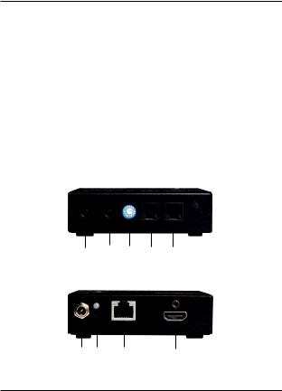
2.6.2 Receivers
1 |
2 |
3 |
4 |
5 |
Figure 2-4. Receiver front panel.
6 7 8 9
Figure 2-5. Receiver back panel.
724-746-5500 | blackbox.com |
Page 15 |
 Loading...