


Black Box LW005A, LW004A, LW009A, LW011A, LW002A User Manual
...
FEBRUARY 1998
LW001A LW004A LW008A LW011A
LW002A LW005A LW009A LW011AE
LW003A LW007A LW010A LW012A LW012AE
3-Mbps Wireless Ethernet
Hubs, Adapters, and Bridges
WirelessHub
Ethernet
|
|
LOAD |
|
|
H |
PWR |
M |
|
INFR |
L |
|
ETHR |
|
|
|
|
QLT |
|
|
H |
PWR |
|
M |
|
L |
|
WLNK |
|
|
ETHR |
|
|
|
QLT |
|
|
|
H |
PWR |
|
M |
|
L |
|
WLNK |
|
|
ETHR |
|
|
|
QLT |
|
|
H |
|
PWR |
M |
|
L |
|
|
WLNK |
|
|
ETHR |
|
|
CUSTOMER SUPPORT INFORMATION
Order toll-free in the U.S.: Call 877-877-BBOX (outside U.S. call 724-746-5500)
FREE technical support 24 hours a day, 7 days a week: Call 724-746-5500 or fax 724-746-0746 Mailing address: Black Box Corporation, 1000 Park Drive, Lawrence, PA 15055-1018
Web site: www.blackbox.com • E-mail: info@blackbox.com

3-MBPS WIRELESS ETHERNET HUBS, ADAPTERS, AND BRIDGES
FEDERAL COMMUNICATIONS COMMISSION
AND
INDUSTRY CANADA
RADIO FREQUENCY INTERFERENCE STATEMENTS
This equipment generates, uses, and can radiate radio frequency energy and if not installed and used properly, that is, in strict accordance with the
manufacturer’s instructions, may cause interference to radio communication. It has been tested and found to comply with the limits for a Class A computing device in accordance with the specifications in Subpart J of Part 15 of FCC rules, which are designed to provide reasonable protection against such interference when the equipment is operated in a commercial environment. Operation of this equipment in a residential area is likely to cause interference, in which case the user at his own expense will be required to take whatever measures may be necessary to correct the interference.
Changes or modifications not expressly approved by the party responsible for compliance could void the user’s authority to operate the equipment.
This digital apparatus does not exceed the Class A limits for radio noise emission from digital apparatus set out in the Radio Interference Regulation of Industry Canada.
Le présent appareil numérique n’émet pas de bruits radioélectriques dépassant les limites applicables aux appareils numériques de classe A prescrites dans le Règlement sur le brouillage radioélectrique publié par Industrie Canada.
The LW001A, LW005A, and LW007A are  certified.
The LW001A, LW005A, and LW007A are UL 19.50 approved.
The LW002A, LW003A, LW004A, LW008A, LW009A, and LW0010A are UL, UL/C, and TUV/GS approved.
All models are ETS 300-328 and VDE Class B approved.
1

3-MBPS WIRELESS ETHERNET HUBS, ADAPTERS, AND BRIDGES
NORMAS OFICIALES MEXICANAS (NOM)
ELECTRICAL SAFETY STATEMENT
INSTRUCCIONES DE SEGURIDAD
1.Todas las instrucciones de seguridad y operación deberán ser leídas antes de que el aparato eléctrico sea operado.
2.Las instrucciones de seguridad y operación deberán ser guardadas para referencia futura.
3.Todas las advertencias en el aparato eléctrico y en sus instrucciones de operación deben ser respetadas.
4.Todas las instrucciones de operación y uso deben ser seguidas.
5.El aparato eléctrico no deberá ser usado cerca del agua—por ejemplo, cerca de la tina de baño, lavabo, sótano mojado o cerca de una alberca, etc..
6.El aparato eléctrico debe ser usado únicamente con carritos o pedestales que sean recomendados por el fabricante.
7.El aparato eléctrico debe ser montado a la pared o al techo sólo como sea recomendado por el fabricante.
8.Servicio—El usuario no debe intentar dar servicio al equipo eléctrico más allá a lo descrito en las instrucciones de operación. Todo otro servicio deberá ser referido a personal de servicio calificado.
9.El aparato eléctrico debe ser situado de tal manera que su posición no interfiera su uso. La colocación del aparato eléctrico sobre una cama, sofá, alfombra o superficie similar puede bloquea la ventilación, no se debe colocar en libreros o gabinetes que impidan el flujo de aire por los orificios de ventilación.
2

3-MBPS WIRELESS ETHERNET HUBS, ADAPTERS, AND BRIDGES
10.El equipo eléctrico deber ser situado fuera del alcance de fuentes de calor como radiadores, registros de calor, estufas u otros aparatos (incluyendo amplificadores) que producen calor.
11.El aparato eléctrico deberá ser connectado a una fuente de poder sólo del tipo descrito en el instructivo de operación, o como se indique en el aparato.
12.Precaución debe ser tomada de tal manera que la tierra fisica y la polarización del equipo no sea eliminada.
13.Los cables de la fuente de poder deben ser guiados de tal manera que no sean pisados ni pellizcados por objetos colocados sobre o contra ellos, poniendo particular atención a los contactos y receptáculos donde salen del aparato.
14.El equipo eléctrico debe ser limpiado únicamente de acuerdo a las recomendaciones del fabricante.
15.En caso de existir, una antena externa deberá ser localizada lejos de las lineas de energia.
16.El cable de corriente deberá ser desconectado del cuando el equipo no sea usado por un largo periodo de tiempo.
17.Cuidado debe ser tomado de tal manera que objectos liquidos no sean derramados sobre la cubierta u orificios de ventilación.
18.Servicio por personal calificado deberá ser provisto cuando:
A:El cable de poder o el contacto ha sido dañado; u
B:Objectos han caído o líquido ha sido derramado dentro del aparato; o
C:El aparato ha sido expuesto a la lluvia; o
D:El aparato parece no operar normalmente o muestra un cambio en su desempeño; o
E:El aparato ha sido tirado o su cubierta ha sido dañada.
3

3-MBPS WIRELESS ETHERNET HUBS, ADAPTERS, AND BRIDGES
TRADEMARKS
Apple® is a registered trademark of Apple Computer, Inc.
Digital™ is a trademark of Digital Equipment Corporation.
HP® is a registered trademark of Hewlett-Packard.
IBM® is a registered trademark of International Business Machines Corporation.
Windows® is a registered trademark of Microsoft Corporation.
ProComm® is a registered trademark of DATASTORM TECHNOLOGIES, INC.™
All applied-for and registered trademarks are the property of their respective owners.
4

3-MBPS WIRELESS ETHERNET HUBS, ADAPTERS, AND BRIDGES
Contents |
|
||
1. |
Specifications.............................................. |
97 |
|
2. |
Quick-Start Setup and Operation |
|
|
|
for the Hub................................................. |
14 |
|
3. |
Introduction ............................................... |
16 |
|
|
3.1 |
The 3-Mbps Wireless Ethernet |
|
|
|
Product Line....................................... |
16 |
|
3.2 |
Features of Wireless LANs ................. |
27 |
4. |
Setting Up the LAN ................................... |
29 |
|
|
4.1 |
Installing the Hub |
|
|
|
(LW001A or LW007A)....................... |
29 |
|
4.2 |
Installing the Workstation Adapter |
|
|
|
(LW002A or LW008A)....................... |
38 |
|
4.3 |
Installing the 4-Port Workstation |
|
|
|
Adapter (LW003A or LW009A) ........ |
45 |
|
4.4 |
Installing the Wireless Bridge |
|
|
|
(LW004A or LW010A)....................... |
55 |
|
4.5 |
Setting Up a Basic Wireless |
|
|
|
Ethernet Cell ...................................... |
63 |
|
4.6 |
Setting Up Overlapping Cells............ |
69 |
|
4.7 |
Associating with a Hub ....................... |
71 |
|
4.8 |
Associating with Other Hubs.............. |
73 |
|
4.9 |
Antennas.............................................. |
74 |
5. |
Advanced Setup.......................................... |
80 |
|
5

3-MBPS WIRELESS ETHERNET HUBS, ADAPTERS, AND BRIDGES
5.1 |
Accessing Advanced Setup |
|
|
|
Functions ............................................ |
80 |
|
|
5.1.1 Hub Main Menu....................... |
87 |
|
|
5.1.2 |
System Configuration |
|
|
|
Menus........................................ |
89 |
|
5.1.3 |
Current Station Parameters..... |
90 |
|
5.1.4 |
IP Related Items ....................... |
91 |
|
5.1.5 WLAN Parameters.................... |
95 |
|
|
5.1.6 Station Control Menu .............. |
105 |
|
5.2 |
Access Control Menu ......................... |
108 |
|
6

3-MBPS WIRELESS ETHERNET HUBS, ADAPTERS, AND BRIDGES
1. Specifications
NOTE
All specifications apply to Hub models LW001A, LW005A, and LW007A, Adapter models LW002A, LW003A, LW008A, and LW009A, and Bridge models LW004A and LW010A, unless otherwise noted.
Radio/Modem
Frequency—2.4 to 2.4835 GHz
Radio type—Spread spectrum, Frequency Hopping
Transmission Power—10 or 100 mW
Modulation—GFSK
Data rate—1, 2, 3 Mbps
Cell size (LW001A, LW002A, LW003A, LW005A,
LW007A, LW008A, LW009A): open air—1000m (3000 feet)
Cell size (LW001A, LW002A, LW003A, LW005A, LW007A, LW008A, LW009A): indoor—200 m (600 feet)
7

3-MBPS WIRELESS ETHERNET HUBS, ADAPTERS, AND BRIDGES
Range, open air (LW004A, LW010A)—Up to 7 miles (10 km)
Antenna diversity—LW001A, LW002A, LW003A, LW005A: 2 attached antennas, 2 dBi omni; LW007A, LW008A, LW009A: 2 detached antennas, 2 dBi omni;
LW004A: 1 or 2 attached antennas, 2 dBi omni; LW010A: 1 or 2 detached antennas, 2 dBi omni
Optional antennas, ordered separately (for use with LW007A, LW008A, LW009A, and LW010A)—6 dBi Omnidirectional Antenna (part
number LW011A); 8.5 dBi Unidirectional Antenna (part number LW012A)
Maximum number of stations supported—256
Wireless LAN Interface
Standard—IEEE 802.11 D2
Media Access Protocol—CSMA/CA
Network Interface
LAN interface—10BASE-T
8
3-MBPS WIRELESS ETHERNET HUBS, ADAPTERS, AND BRIDGES
Standards—IEEE 802.3, IEEE 802.1d, Transparent to network protocols (IP, IPX, Appletalk, OSI, NetBIOS, DECnet, etc.)
LED Indicators (LW001A, LW005A, LW007A):
Power and Self-Test—PWR
Wired LAN activity—ETHR
Radio Interference—INFR
Wireless LAN load (3 LEDs)—H (High), M (Medium), L (Low)
LED Indicators (LW002A, LW003A, LW004A, LW008A,
LW009A, LW010A):
Power and Self-Test
Wireless Link
Wired LAN activity
Wireless LAN signal quality (3 LEDs)
9

3-MBPS WIRELESS ETHERNET HUBS, ADAPTERS, AND BRIDGES
Security (LW004A, LW010A):
Encryption—802.11 compatible
Authentication—Network ID, Password
Management (LW001A, LW005A, LW007A):
SNMP agent—MIB-II, bridge MIB, Radio MIB
Wired Ethernet, serial SLIP, and wireless management access
Software download by TFTP
Local monitor (RS-232)
Management (LW002A, LW008A):
SNMP agent—MIB-I and II, bridge MIB, Private MIB
Wired Ethernet and wireless management access Software downloaded by TFTP
10

3-MBPS WIRELESS ETHERNET HUBS, ADAPTERS, AND BRIDGES
Management (LW003A, LW009A):
SNMP agent—MIB-1 and II, bridge MIB, Private MIB
Wired Ethernet, serial SLIP, and wireless management access
Software downloaded by TFTP
Management (LW004A, LW010A):
SNMP agent—MIB-II, bridge MIB, Radio MIB
Wired Ethernet, serial SLIP, and wireless management access
Software downloaded by TFTP
Local monitor (RS-232)
Electrical
External power supply—100-250 VAC, autosensing
Input voltage—5 VDC, 1200mA
11

3-MBPS WIRELESS ETHERNET HUBS, ADAPTERS, AND BRIDGES
Dimensions
5.1”H x 3.4”W x 1.2”D (13 x 8.6 x 3 cm)
Weight
1 lb. (0.45 kg)
Environmental
Operating temperature—32° to 105° F (0° to 40° C)
Operating humidity—5% to 95% non-condensing
Immunity
Will maintain link under all conditions—Per EN 50082-1
12

3-MBPS WIRELESS ETHERNET HUBS, ADAPTERS, AND BRIDGES
Approvals (LW001A, LW005A, LW007A):
UL 19.50
FCC Part 15
ETS 300-328
VDE Class B
CE
Approvals (LW002A, LW003A, LW004A, LW008A,
LW009A, LW010A):
UL, UL/C, TUV/GS
FCC Part 15
ETS 300-328
VDE Class B
13

3-MBPS WIRELESS ETHERNET HUBS, ADAPTERS, AND BRIDGES
2. Quick Start Setup and
Operation for the Hub
Use the following steps to get up and running with your 3-Mbps Wireless Ethernet Hub. (For more detailed procedures, see Section 4.1.)
1. Position the Hub in a high, central location, well away from moving objects and metal furniture.
NOTE
When using more than one Hub, make sure to define different hopping sequences for each Access Point. See Chapter 5.
2.Connect the power transformer to a 110/220 VAC power supply and to the DC input socket on the Hub.
3.Connect the Hub to the Ethernet backbone by attaching one end of a regular, uncrossed 10BASE-T cable (not supplied) to the RJ-45 port on the back panel of the Hub (marked UTP). Attach the other end of the connector cable to any available Ethernet hub port.
14

3-MBPS WIRELESS ETHERNET HUBS, ADAPTERS, AND BRIDGES
4. Check the function of the Hub using the front-panel LED indicators as follows:
•PWR—Power supply
•INFR—Radio interference
•ETH—Ethernet activity
•LOAD—Number of associated stations (Low, Medium, High)
15

3-MBPS WIRELESS ETHERNET HUBS, ADAPTERS, AND BRIDGES
3.Introduction
3.1The 3-Mbps Wireless Ethernet Product Line
The Wireless Ethernet product line contains the following units:
•Wireless Ethernet Hub (LW001A, LW005A, or LW007A)
•Wireless Ethernet Workstation Adapter (LW002A or LW008A)
•Wireless Ethernet Four-Port Workstation Adapter (LW003A or LW009A)
•Wireless Ethernet Wireless Bridge (LW004A or LW010A)
WIRELESS ETHERNET HUB (LW001A, LW005A, OR LW007A)
The Wireless Ethernet Hub (LW001A) is a wireless Hub that provides access for the wireless workstation users into wired Ethernet LANs.
The Wireless Ethernet Hub for PCMCIA (LW005A) is the same as the LW001A, except that the LW005A must be used with the PCMCIA Wireless Adapter (LW006A). Any reference in this manual to the LW001A also applies to the LW005A.
16

3-MBPS WIRELESS ETHERNET HUBS, ADAPTERS, AND BRIDGES
The LW001A and LW007A function exactly the same way, but the LW001A has permanently attached antennas, and the LW007A has detachable antennas. A third Hub, LW005A (which is covered in a separate manual), has the same hardware as the LW007A, but different software. It works with portable computers equipped with the PCMCIA Wireless Adapter (LW006A) to connect to wired Ethernet LANs.
The Hub also contains the coordinating function that enables workstations to communicate through it to one another inside the cell coverage area, even though they may not be in direct line of sight. Mobile workstations can roam from one Hub to another that belongs to the same extended wireless network. When Hubs are set up in such a way that their coverage areas overlap one another, users may roam seamlessly from cell to cell. The Workstation Adapters “decide” when a mobile user becomes disassociated from one Hub and associated with another.
This process is fully transparent, requires no user intervention, and involves no loss of data packets.
You can position multiple Hubs in locations where you expect heavy network traffic. This will increase the throughput capacity in the areas where you most need it.
17
3-MBPS WIRELESS ETHERNET HUBS, ADAPTERS, AND BRIDGES
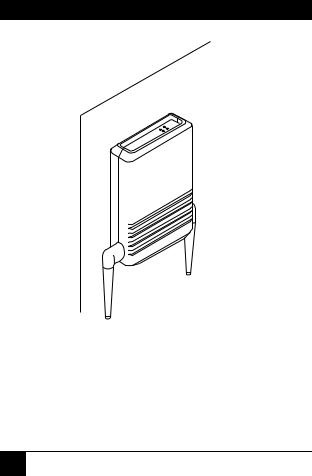
Figure 3-1. Wireless Ethernet Hub (LW001A or LW007A) Installed on Wall.
The Wireless Ethernet Hub contains an embedded SNMP agent that lets you manage it from the LAN Management Information Base. Software upgrades are downloaded by TFTP.
18
3-MBPS WIRELESS ETHERNET HUBS, ADAPTERS, AND BRIDGES
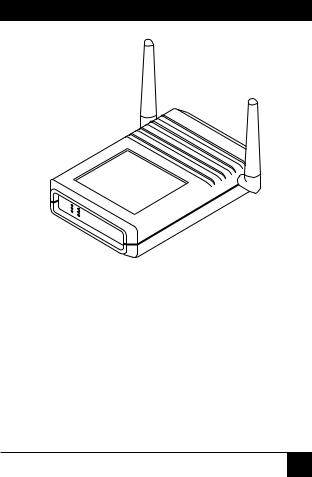
Figure 3-2. Wireless Ethernet Hub (LW001A or LW007A) Installed on Shelf.
19

3-MBPS WIRELESS ETHERNET HUBS, ADAPTERS, AND BRIDGES
WIRELESS ETHERNET WORKSTATION ADAPTER (LW002A OR
LW008A)
The LW002A is a wireless LAN adapter that converts any 10BASE-T Ethernet equipped computer (including PCs, X-Terminals, Digital™, Sun, HP®, IBM®, and Apple®), into a wireless LAN station. The LW002A is transparent to the computer’s hardware and software. This enables plug-and-play installation.
The LW002A and LW008A function exactly the same way, but the LW002A has permanently attached antennas, and the LW008A has detachable antennas.
The Workstation Adapter can communicate with any other workstation adapters in its coverage area, or via the Wireless Ethernet Hub to all of the network resources such as file servers, printers and shared databases.
The Workstation Adapter contains an embedded SNMP agent that lets you effectively manage it from the LAN Management Information Base. Software upgrades are downloaded by TFTP.
20
3-MBPS WIRELESS ETHERNET HUBS, ADAPTERS, AND BRIDGES
Figure 3-3. Workstation Adapter (LW002A or LW008A).
The network stays connected while you roam between overlapping coverage areas; plus, you get continuous transmission and reception while moving at high speed without losing or duplicating data packets.
21

3-MBPS WIRELESS ETHERNET HUBS, ADAPTERS, AND BRIDGES
WIRELESS ETHERNET 4-PORT WORKSTATION ADAPTER
(LW003A OR LW009A)
The Wireless Ethernet 4-Port Workstation Adapter (LW003A) is a wireless LAN adapter that connects a workgroup of up to four 10BASE-T Ethernet equipped workstations to the wireless LAN. Workstations that can be converted by the 4-Port Workstation Adapter into wireless LAN stations include PCs,
X-Terminals, Digital, SUN, HP, IBM and Apple computers. The Adapter is transparent to the workgroup computers’ hardware and software.
The LW003A and LW009A function exactly the same, but the LW003A has permanently attached antennas, and the LW009A has detachable antennas.
The 4-Port Workstation Adapter lets connected workstations communicate with other Wireless Ethernet stations in its coverage area, or via the Wireless Ethernet Hub (LW001A or LW007A) to all of the network resources such as file servers, printers and shared databases. The 4-Port Workstation Adapter also allows highly efficient and fast wired communication between the connected workstations.
22

3-MBPS WIRELESS ETHERNET HUBS, ADAPTERS, AND BRIDGES
The 4-Port Workstation Adapter contains an embedded SNMP agent and software downloading capabilities that let you manage it from the LAN Management Information Base.
Figure 3-4. 4-Port Workstation Adapter (LW003A or LW009A).
23

3-MBPS WIRELESS ETHERNET HUBS, ADAPTERS, AND BRIDGES
WIRELESS BRIDGE (LW004A OR LW010A)
The Wireless Bridge (LW004A) is a high-speed, widerange wireless LAN bridge that provides connectivity to remote Ethernet networks.
The LW004A and LW010A function exactly the same way, but the LW004A has permanently attached antennas, and the LW010A has detachable antennas.
The LW004A communicates with the Wireless Ethernet Hubs (LW001A) of the remote LANs, and the LW010A communicates with the Wireless Ethernet Hub (LW007A) of the remote LANs. This effectively creates an extended wireless network spanning sites situated up to 7 miles apart. In this way a central Ethernet LAN may be connected with one or more branch office LANs.
The Wireless Bridge also allows connectivity between a wireless LAN and individual workstations or workgroups located outside the LAN.
WIRELESS ETHERNET HUB FOR PCMCIA ADAPTER
(LW005A)
The LW005A Hub, which is covered in detail in a separate user manual, is physically identical to the LW007A, but has different software. It works with portable computers equipped with the PCMCIA Wireless Adapter (LW006A) to connect to wired Ethernet LANs.
24

3-MBPS WIRELESS ETHERNET HUBS, ADAPTERS, AND BRIDGES
PCMCIA WIRELESS ADAPTER (LW006A)
The LW006A adapter, which is covered in detail in a separate user manual, gives the portable computer user complete mobility, allowing seamless roaming throughout the wireless LAN campus.
The PCMCIA Wireless Adapter converts any portable computer (notebook, laptop, pen-based, etc.) containing a PCMCIA Release 2.1 Type II slot into a wireless LAN station.
The LW006A adapter can communicate with any other wireless station in its coverage area, and can access all of the network resources like file servers, printers and shared databases via the Wireless Ethernet Hub (LW005A, covered in a separate manual).
The network stays connected while you roam between overlapping coverage areas; plus, you get continuous transmission and reception while moving at high speed without losing or duplicating data packets.
25
3-MBPS WIRELESS ETHERNET HUBS, ADAPTERS, AND BRIDGES
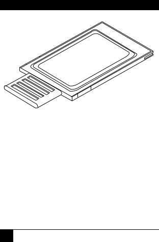
Figure 3-5. PCMCIA Wireless Adapter (LW006A).
WIRELESS BRIDGE FOR PCMCIA ADAPTER (LW005A)
The Wireless Bridge for PCMCIA Adapter is covered in a separate user manual.
OPTIONAL ANTENNAS (LW011A AND LW012A)
The 6 dBi Omnidirectional Antenna (LW011A) and the Unidirectional Antenna (LW012A) work only with the LW005A and LW007A Hubs, LW008A and LW009A Adapters, and LW010A Bridge.
26

3-MBPS WIRELESS ETHERNET HUBS, ADAPTERS, AND BRIDGES
3.2Features of Wireless Ethernet LANs
•Saves cabling costs—The wireless Ethernet LAN saves you cabling costs that can amount to up to 40% of your LAN installation cost.
•Plug-and-play installation—No additional software or hardware installation is required. After connecting the units to the power supply and connecting the Hubs to the wired LAN, your Wireless Ethernet system is ready to operate.
•Flexibility—The wireless Ethernet LAN provides an effective communication solution for:
-Campus environments
-Temporary or leased offices
-Trade shows
-Manufacturing environments
-Hospital applications
-Harbors and airports
-Buildings that are difficult to wire
-Points of sale
27

3-MBPS WIRELESS ETHERNET HUBS, ADAPTERS, AND BRIDGES
•Workstation mobility—Notebook and pen-based computer users can roam throughout the Wireless Ethernet campus. As long as the coverage areas are overlapping this mobility is seamless. Users maintain their network connection while roaming from cell to cell.
•Quickly extends wired LAN—A Wireless Ethernet LAN cell gives instant add-on capability to your wired LAN for temporary or permanent expansion.
•Technical Advantages
-High data rate of 3 Mbps, with automatic fallback to 2 and 1 Mbps.
-License-free use (2.4GHz ISM band, FHSS)
-15 Mbps aggregate throughput in the same coverage area by multiple Hubs.
-Antenna diversity and DSP modem ensure robust communication.
-Software, including modem module, upgraded by downloading.
-Security is provided by Spread Spectrum Frequency Hopping and Network ID.
-Simple network management support (SNMP).
28
 Loading...