


LPB708A
LPB716A
LPB724A
8-/16-/24-Port 10/100 PoE PSE Web Smart Switch
Connect VoIP phones, IP cameras, or any PoE PD devices through manageable, switched links.
Complies with 802.af Power-over Ethernet standard. Supports Web-based configuration and management. Uses Auto-MDI/MDI-X so you can use crossover
or straight-through cables. Automatically determines port speed. Housed in a desktop metal case with an internal power supply.
Includes PoE ON/OFF remote control.

8-/16-/24-Port 10/100 PoE PSE Web Smart Switch
Federal Communications Commission and Industry Canada Radio Frequency Interference
Statements
This equipment generates, uses, and can radiate radio-frequency energy, and if not installed and used properly, that is, in strict accordance with the manufacturer’s instructions, may cause interference to radio communication. It has been tested and found to comply with the limits for a Class A computing device in accordance with the specifications in Subpart J of Part 15 of FCC rules, which are designed to provide reasonable protection against such interference when the equipment is operated in a commercial environment. Operation of this equipment in a residential area is likely to cause interference, in which case the user at his own expense will be required to take whatever measures may be necessary to correct the interference.
Changes or modifications not expressly approved by the party responsible for compliance could void the user’s authority to operate the equipment.
This digital apparatus does not exceed the Class A limits for radio noise emission from digital apparatus set out in the Radio Interference Regulation of Industry Canada.
Le présent appareil numérique n’émet pas de bruits radioélectriques dépassant les limites applicables aux appareils numériques de la classe A prescrites dans le Règlement sur le brouillage radioélectrique publié par Industrie Canada.
2 |
724-746-5500 l www.blackbox.com |
|

NOM Statement and CE Directive
Normas Oficiales Mexicanas (NOM) Electrical Safety Statement
INSTRUCCIONES DE SEGURIDAD
1.Todas las instrucciones de seguridad y operación deberán ser leídas antes de que el aparato eléctrico sea operado.
2.Las instrucciones de seguridad y operación deberán ser guardadas para referencia futura.
3.Todas las advertencias en el aparato eléctrico y en sus instrucciones de operación deben ser respetadas.
4.Todas las instrucciones de operación y uso deben ser seguidas.
5.El aparato eléctrico no deberá ser usado cerca del agua—por ejemplo, cerca de la tina de baño, lavabo, sótano mojado o cerca de una alberca, etc..
6.El aparato eléctrico debe ser usado únicamente con carritos o pedestales que sean recomendados por el fabricante.
7.El aparato eléctrico debe ser montado a la pared o al techo sólo como sea recomendado por el fabricante.
8.Servicio—El usuario no debe intentar dar servicio al equipo eléctrico más allá a lo descrito en las instrucciones de operación. Todo otro servicio deberá ser referido a personal de servicio calificado.
9.El aparato eléctrico debe ser situado de tal manera que su posición no interfiera su uso. La colocación del aparato eléctrico sobre una cama, sofá, alfombra o superficie similar puede bloquea la ventilación, no se debe colocar en libreros o gabinetes que impidan el flujo de aire por los orificios de ventilación.
10.El equipo eléctrico deber ser situado fuera del alcance de fuentes de calor como radiadores, registros de calor, estufas u otros aparatos (incluyendo amplificadores) que producen calor.
11.El aparato eléctrico deberá ser connectado a una fuente de poder sólo del tipo descrito en el instructivo de operación,
o como se indique en el aparato.
12.Precaución debe ser tomada de tal manera que la tierra fisica y la polarización del equipo no sea eliminada.
13.Los cables de la fuente de poder deben ser guiados de tal manera que no sean pisados ni pellizcados por objetos colocados sobre o contra ellos, poniendo particular atención a los contactos y receptáculos donde salen del aparato.
14.El equipo eléctrico debe ser limpiado únicamente de acuerdo a las recomendaciones del fabricante.
15.En caso de existir, una antena externa deberá ser localizada lejos de las lineas de energia.
16.El cable de corriente deberá ser desconectado del cuando el equipo no sea usado por un largo periodo de tiempo.
17.Cuidado debe ser tomado de tal manera que objectos liquidos no sean derramados sobre la cubierta u orificios de ventilación.
18.Servicio por personal calificado deberá ser provisto cuando:
A:El cable de poder o el contacto ha sido dañado; u
B:Objectos han caído o líquido ha sido derramado dentro del aparato; o
C:El aparato ha sido expuesto a la lluvia; o
D:El aparato parece no operar normalmente o muestra un cambio en su desempeño; o
E:El aparato ha sido tirado o su cubierta ha sido dañada.
European Community (CE) Electromagnetic Compatibility Directive
This equipment has been tested and found to comply with the protection requirements of European Emission Standard EN55022/EN61000-3 and the Generic European Immunity Standard EN55024.
EMC:
EN55022 (2003)/CISPR-2 (2002): class A IEC61000-4-2 (2001): 4KV CD, 8KV AD IEC61000-4-3 (2002): 3V/m
IEC61000-4-4 (2001):1KV (power line), 0.5KV (signal line)
724-746-5500 l www.blackbox.com 3

8-/16-/24-Port 10/100 PoE PSE Web Smart Switch
Table of Contents
1. |
Specifications |
.................................................................................................................................................................. |
6 |
|
|
1.1 |
Hardware Specifications ........................................................................................................................................ |
6 |
|
|
1.2 |
Management Software Specifications .................................................................................................................. |
7 |
|
2. |
Overview |
.................................................................................................................................................................. |
8 |
|
|
2.1 |
Introduction ............................................................................................................................................................. |
8 |
|
|
2.2 |
Features |
.................................................................................................................................................................. |
8 |
|
2.3 |
What’s Included ..................................................................................................................................................... |
8 |
|
|
2.4 |
Front and Rear Panels .......................................................................................................................................... |
9 |
|
|
|
2.4.1 |
Front Panel............................................................................................................................................... |
9 |
|
|
2.4.2 |
Back Panel ............................................................................................................................................... |
9 |
|
2.5 |
LED Indicators ..................................................................................................................................................... |
10 |
|
3. |
Installation |
................................................................................................................................................................ |
12 |
|
|
3.1 |
Hardware and Cable Installation ........................................................................................................................ |
12 |
|
|
|
3.1.1 |
TP Port and Cable Installation ............................................................................................................. |
12 |
|
|
3.1.2 |
Installing Optional SFP Transceiver Module ...................................................................................... |
12 |
|
|
3.1.3 |
Power On .............................................................................................................................................. |
13 |
|
3.2 |
Installing Switch to 19-inch Wiring Closet Rail .................................................................................................. |
13 |
|
|
3.3 |
Cabling Requirement ........................................................................................................................................... |
13 |
|
|
3.4 |
Switch Cascading in Topology ............................................................................................................................ |
14 |
|
|
3.5 |
Typical Network Topology in Deployment .......................................................................................................... |
14 |
|
|
3.6 |
Set IP Address, Subnet Mask, and Default Gateway IP Address..................................................................... |
16 |
|
4. Operation of Web-based Management ......................................................................................................................... |
18 |
|||
|
4.1 |
Web Management Home Overview .................................................................................................................... |
19 |
|
|
4.2 |
Administrator ........................................................................................................................................................ |
19 |
|
|
|
4.2.1 |
Authentication Configuration ................................................................................................................ |
20 |
|
|
4.2.2 |
System IP Configuration ...................................................................................................................... |
20 |
|
|
4.2.3 |
System Status ....................................................................................................................................... |
21 |
|
|
4.2.4 |
Load Default Setting ............................................................................................................................. |
22 |
|
|
4.2.5 |
Firmware Update .................................................................................................................................. |
22 |
|
|
4.2.6 |
Reboot Device ...................................................................................................................................... |
22 |
|
4.3 |
Port Management ................................................................................................................................................ |
22 |
|
|
|
4.3.1 |
Port Configuration ................................................................................................................................. |
23 |
|
|
4.3.2 |
Port Mirroring ........................................................................................................................................ |
23 |
|
|
4.3.3 |
Bandwidth Control ................................................................................................................................ |
24 |
|
|
4.3.4 |
Broadcast Storm Control....................................................................................................................... |
25 |
|
|
4.3.5 |
PoE ........................................................................................................................................................ |
25 |
|
4.4 |
VLAN Setting ....................................................................................................................................................... |
26 |
|
|
|
4.4.1 |
VLAN Mode............................................................................................................................................ |
26 |
|
|
4.4.2 |
Port-based VLAN—VLAN Member ...................................................................................................... |
26 |
|
|
4.4.3 |
Tag-based VLAN1 ................................................................................................................................. |
27 |
|
|
4.4.4 |
Tag-based VLAN—VLAN Member....................................................................................................... |
28 |
|
|
4.4.5 |
Multi to 2 Setting .................................................................................................................................... |
29 |
|
4.5 |
Per Port Counter................................................................................................................................................... |
30 |
|
|
|
4.5.1 |
Counter Category .................................................................................................................................. |
30 |
|
4.6 |
QoS Setting........................................................................................................................................................... |
31 |
|
|
|
4.6.1 |
Priority Mode .......................................................................................................................................... |
31 |
|
|
4.6.2 |
Class of Service .................................................................................................................................... |
31 |
|
|
4.6.3 |
Class of Service—TCP/UDP ................................................................................................................ |
32 |
|
|
4.6.4 |
Class of Service—IP TOS/DS .............................................................................................................. |
33 |
|
|
4.6.5 |
Class of Service—802.1p ..................................................................................................................... |
33 |
|
|
4.6.6 |
Class of Service—Physical Port........................................................................................................... |
34 |
|
4.7 |
Security |
................................................................................................................................................................ |
34 |
|
|
4.7.1 |
MAC Address Configuration ................................................................................................................. |
34 |
|
|
4.7.2 |
TCP/UDP Filter Configuration............................................................................................................... |
35 |
4 |
724-746-5500 l www.blackbox.com |
|

|
|
|
|
|
Table of Contents |
|
|
|
|
|
|
|
|
|
|
|
|
|
|
|
|
|
4.8 |
Spanning Tree |
36 |
|
|
|
|
|
||||
|
|
|
4.8.1 |
STP Bridge Setting ................................................................................................................................ |
36 |
|
|
|
|
4.8.2 |
STP Port Setting .................................................................................................................................... |
37 |
|
|
|
4.9 |
Trunking |
................................................................................................................................................................ |
38 |
|
|
|
4.10 |
Backup/Recovery ................................................................................................................................................. |
40 |
|
|
|
|
4.11 |
Miscellaneous Setting .......................................................................................................................................... |
40 |
|
|
|
|
4.12 |
Logout |
................................................................................................................................................................ |
41 |
|
5. |
Troubleshooting ............................................................................................................................................................... |
42 |
|
|||
6. |
IP Address Assignment................................................................................................................................................... |
43 |
|
|||
|
|
6.1 |
IP Address............................................................................................................................................................. |
43 |
|
|
|
|
6.2 |
Subnet Mask ......................................................................................................................................................... |
43 |
|
|
|
|
6.3 |
Default Gateway ................................................................................................................................................... |
44 |
|
|
|
|
6.4 |
DNS |
................................................................................................................................................................ |
45 |
|
724-746-5500 l www.blackbox.com 5

8-/16-/24-Port 10/100 PoE PSE Web Smart Switch
1. Specifications
Hardware Specifications
Buffer Memory: LPB708A, LPB716A: Embedded 1625 K bits frame buffer;
LPB724A: 2750 K bits
Certifications: FCC Class A, CE
Flow Control: IEEE802.3x compliant for full duplex;
Backpressure flow control for half duplex
Full Forwarding/Filtering Packet Rate: PPS (packets per second):
Forwarding Rate |
Speed |
148,800 PPS |
100 Mbps |
14,880 PPS |
10 Mbps |
MAC Address and Self-learning: 4K MAC address
Network Interface: 8-port/ 16-port/ 24-port 10/100BaseT(X) with PoE (half/full power); 2-port combo UTP/SFP Gigabit (LPB724A only)
Standards Compliance: IEEE 802.3 10BASE-T, IEEE 802.3u 100BASE-TX, IEEE 802.3x Flow Control, IEEE 802.3ad Trunk, IEEE 802.3af Power over Ethernet (PoE), IEEE 802.1Q VLAN, IEEE 802.1p QoS,
IEEE 802.1x Port-based Network Access Control, IEEE 802.1d Spanning Tree Protocol, IEEE 802.1w Rapid Spanning Tree Protocol
Switching Method: Store and forward
Transmission Media: 10BASE-T CAT3, 4, 5 UTP/STP; 100BASE-TX CAT5 UTP/STP
Transmission Mode: 10/100Mbps support fullor half-duplex
Transmission Speed: 10/100 Mbps for TP
Connectors: LPB708A: (8) RJ-45;
LPB716A: (16) RJ-45;
LPB724A: (24) RJ-45, (2) combo UTP/SFP
Indicators: LEDs: Per Port: LINK/ACT;
PoE Port: Act/Status;
Per Unit: Power
Temperature Tolerance: Operating: 32 to 131° F (0 to 55°C);
Storage Temperature: -4 to 194°F (-20 to 90 C)
Humidity Tolerance: 10 to 90% RH (non-condensing)
Power: Input: 100–240V/AC, 50–60Hz;
PoE Power Output: 15.4 Watts (Max) per port
Power Consumption: LPB708A: 130 Watts (maximum); LPB716A: 260 Watts (maximum); LPB724A: 390 Watts (maximum)
Size: LPB708A: 1.7”H x 6.3”W x 10.5”D (4.4 x 16 x 26.6 cm);
LPB716A, LPB724A: 1.7”H x 8.7”W x 17.3”D (4.4 x 22 x 44 cm)
Weight: LPB708A: 3.5 lb. (1.6 kg); LPB716A: 7.9 lb. (3.6 kg); LPB724A: 8.6 lb. (3.9 kg)
6 |
724-746-5500 l www.blackbox.com |
|

Chapter 1: Specifications
Management Software Specifications
Backup/Recovery Configuration
IGMP Snooping: V1/V2
Port Management: Port Configuration, Port Mirroring, Bandwidth Control, Broadcast Strom Control, PoE On/ Off Setting
QoS Setting: Up to 4 queues
RSTP/STP: Rapid/Spanning Tree Protocol
VLAN Function: Port-Based/802.1Q-Tagged, up to 256 active VLANs in one switch
VLAN Setting: Port-based/Tag-based, VLAN ID: 1–4094K
Security Filter: MAC address filtering, TCP/UDP filtering
Trunking: 2 groups (1–4 ports for each group)
724-746-5500 l www.blackbox.com 7

8-/16-/24-Port 10/100 PoE PSE Web Smart Switch
2. Overview
2.1 Introduction
LPB708A/LPB716A/LPB724A, is a standard 8-Port/16-Port/24-Port 10/100 PoE PSE Web Smart Switch that meets all IEEE 802.3u/x Ethernet specifications. The switch includes 8-, 16-, or 24-Port 10/100Mbps TP ports. LPB724A also features two combo UTP/SFP Gigibit ports. Manage the switch through an Ethernet port using Web-based management. The switch also features QoS (Quality of Service), Spanning Tree, VLAN, Port Trunking, and IGMP Snooping capability via the intelligent software. It is suitable for smalland medium-sized office applications.
This PSE switch also complies with IEEE 802.3af. Its advanced autosensing algorithm enables power devices (PD) discovery, classification, current limit, and other necessary functions. Safety features include short-circuit protection and power-out auto-detection to PD.
2.2 Features
Power-over-Ethernet: Provides built-in 802.3af Power over Ethernet for network sites that need to run power over the network cables. Each of the 10/100BASE-TX Ethernet ports on this switch provides up to 15.4 watts power for connected wireless access points, IP phones and other PoE-supported devices, enabling them to be deployed at difficult places such as on high walls and ceilings, where AC power outlets are not readily available.
QoS: Supports Quality of Service by the IEEE 802.1P standard. There are four priority queues enabling users to run bandwidth-sensitive applications such as streaming multimedia and VoIP in network.
Spanning Tree: Supports IEEE 802.1D, IEEE 802.1w (RSTP: Rapid Spanning Tree Protocol) standards to prevent network loops that could cause a broadcast storm.
VLAN: Supports Port-based VLAN and IEEE802.1Q Tag VLAN. Also supports 256 active VLANs and VLAN ID 1– 4094.
Port Trunking: Supports static port trunking and port trunking with IEEE 802.3ad LACP.
IGMP Snooping: Establishes the multicast groups to forward the multicast packet to the member ports, and avoids wasting the bandwidth while IP multicast packets are running over the network.
Security: Support MAC Address and TCP/UDP filtering to prevent unknown users or un-authorized actions connected to network.
2.3 What’s Included
Your package should include the following items. If anything is missing or damaged, contact Black Box Technical Support at 724-746-5500 or info@blackbox.com.
(1) 8-, or 16-, or 24-Port 10/100 PoE PSE Web Smart Switch
(1) Mounting Accessory (for 19” Rackmount)
(1) AC Power Cord
(1) CD-ROM containing this user’s manual in PDF format
8 |
724-746-5500 l www.blackbox.com |
|
Chapter 2: Overview
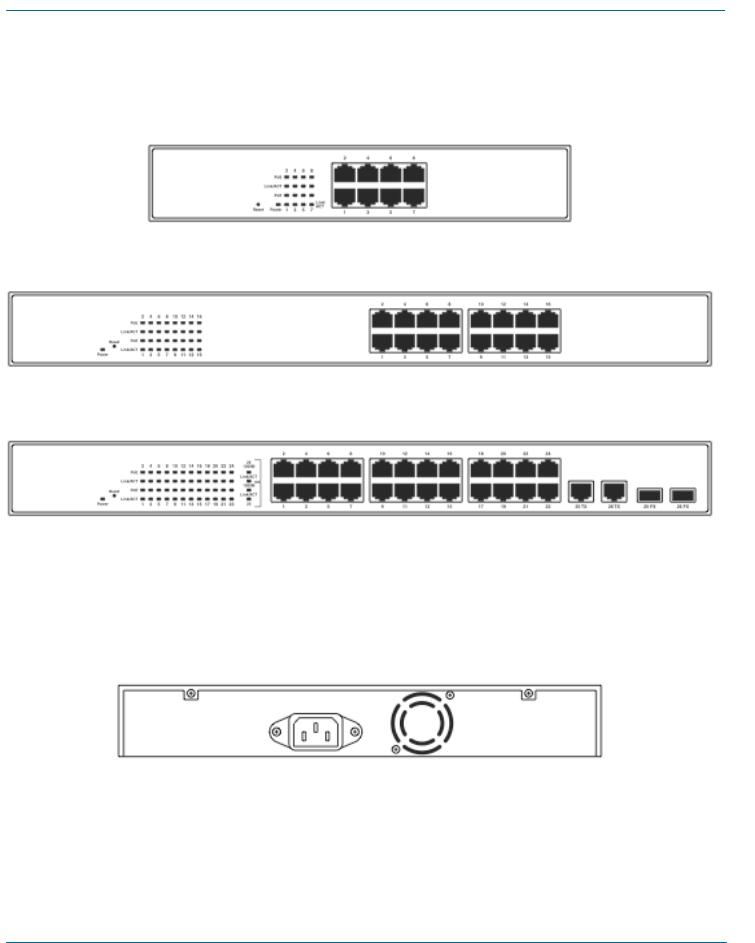
2.4 Front and Back Panels
2.4.1 Front Panel
LED Indicators |
8 RJ-45 TP ports |
LPB708A.
LED Indicators
(16) RJ-45 TP ports
|
LPB716A. |
|
|
|
2 Combo UTP/SFP |
LED Indicators |
24 RJ-45 TP Ports |
Ports |
LPB724A.
Figure 2-1. LPB708A, LPB716A, LPB724A Front panels.
2.4.2 Back Panel
AC Power Input
Figure 2-2. Back panel.
724-746-5500 l www.blackbox.com 9
8-/16-/24-Port 10/100 PoE PSE Web Smart Switch
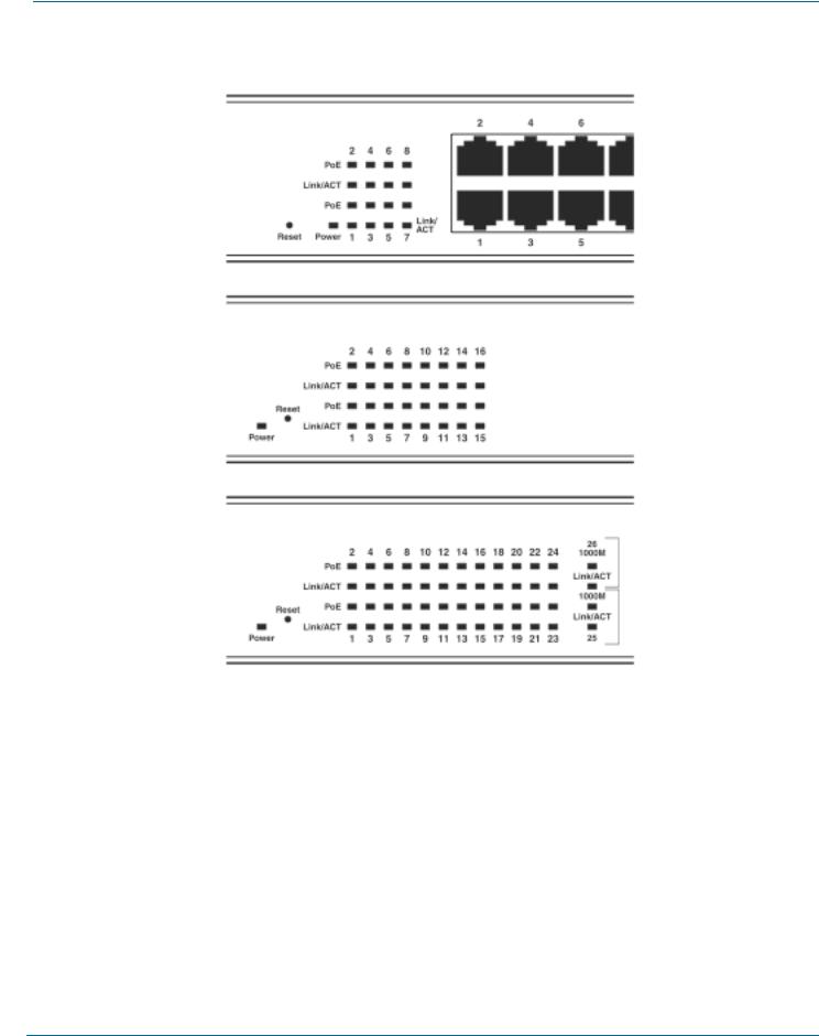
2.5 LED Indicators
LPB708A
LPB716A
LPB724A
Figure 2-3. LED Indicators.
10 |
724-746-5500 l www.blackbox.com |
|
Chapter 2: Overview
Table 2-1. LED descriptions.
LED |
Color |
Function |
Systems LED (All models) |
|
|
Power |
Green |
Lit when power is on |
Reset |
|
Used to restore management system |
10/100 Ethernet TP Port 1 to 8 LEDs (LPB708A) |
|
|
LINK/ACT |
Green |
Blinks when any traffic is present |
|
|
Off when connection is not good |
PoE |
Green |
Lit when PoE power is active |
10/100 Ethernet TP Port 1 to 16 LEDs (LPB716A) |
||
LINK/ACT |
Green |
Blinks when any traffic is present |
|
|
Off when connection is not good |
PoE |
Green |
Lit when PoE power is active |
10/100 Ethernet TP Port 1 to 24 plus 2 Gigabit Combo Port LEDs (LPB724A) |
||
LINK/ACT |
Green |
Blinks when any traffic is present |
|
|
Off when connection is not good |
PoE |
Green |
Lit when PoE power is active |
1000M |
Green |
Lit when connected at 1000-Mbps |
724-746-5500 l www.blackbox.com 11
8-/16-/24-Port 10/100 PoE PSE Web Smart Switch
3. Installation
3.1 Hardware and Cable Installation
CAUTION: Wear a grounding device to avoid damage from electrostatic discharge. Be sure that the power switch is OFF before you connect the power cord to the power source.
3.1.1 TP Port and Cable Installation
1.The switch’s TP port supports MDI/MDI-X auto-crossover, so you can use both types of cable, straight-through (Cable pin-outs for RJ-45 jack 1, 2, 3, 6 to 1, 2, 3, 6 in 10/100M TP) and cross-over (Cable pin-outs for RJ-45 jack 1, 2, 3, 6 to 3, 6, 1, 2). Simply plug in the cable.
2.Connect one end of a CAT5 grade RJ-45 TP cable or above to a TP port on the switch and connect the other end to a network-aware device such as a workstation or a server.
3.Repeat the above steps, as needed, for each RJ-45 port that you want to connect to a 10/100 TP device.
The switch is now ready to operate.
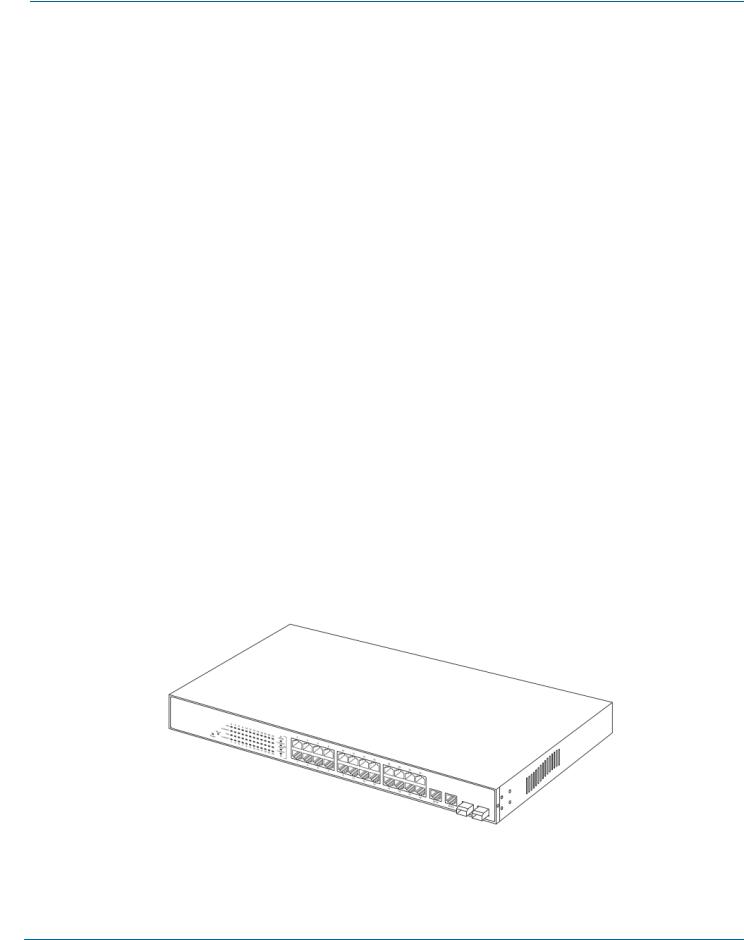
3.1.2 Installing an Optional SFP Transceiver Module
NOTE: If you do not plan to install SFP fiber transceivers in the LPB724A switch’s ports 25–26, skip this section.
Slide the fiber transceiver module into one of the two open module slots in the switch as shown in Figure 3-1. Connecting the SFP Module to the Chassis
The optional SFP modules are hot-swappable, so you can plug or unplug them before or after powering on the switch. Verify that the SFP module is the right model and conforms to the chassis.
Slide the module into the slot. Make sure that the module is properly seated against the slot socket/connector. Connect the fiber optic network cable to the connector(s) on the module.
If you want to install a second module in the switch, repeat steps 1–3.
SFP transceiver module
Figure 3-1. Installing an SFP fiber transceiver into the LPB724A switch.
12 |
724-746-5500 l www.blackbox.com |
|
Chapter 3: Installation
3.1.3 Power On
The switch supports a 100-240 VAC, 50-60 Hz power supply. The power supply will automatically convert the local AC power source to DC power. It does not matter whether any connection is plugged into the switch or not when powering on. After the power is on, all LED indicators will light immediately and then all go off except the power LED, which stays on.
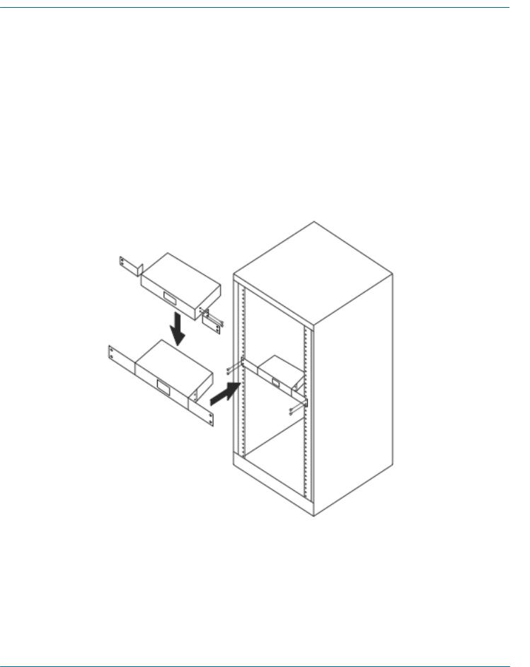
3.2 Installing Switch to a 19-Inch Wiring Closet Rail
CAUTION: Allow a proper spacing and proper air ventilation for the cooling fan at both sides of the switch. Wear a grounding device for electrostatic discharge.
1.Using two screws (included), attach the rackmount ears to the switch’s left and right sides. See Figure 3-2.
2.Line up the mounting holes on the switch assembly (the switch with rackmount ears installed) with the mounting holes on a 19" wiring closet rack. Install two screws (included) to hold the switch in place in the rack.
Figure 3-2. Install the switch chassis in a 19"rack.
3.3 Cabling Requirements
To ensure a successful installation and maintain proper network performance, use the required cable types. Cables with lesser specification will cause the LAN to work poorly.
For a Fast Ethernet TP network connection, the cable grade must be CAT5 or CAT5e that‘s up to 328 feet (100 meters) long.
724-746-5500 l www.blackbox.com 13
8-/16-/24-Port 10/100 PoE PSE Web Smart Switch
3.4 Switch Cascading in Topology
Theoretically, the switch partitions the collision domain for each port in switch cascading so that you may uplink an unlimited number of switches. In practice, the network extension (cascading levels and overall diameter) must comply with the IEEE 802.3/802.3u and other 802.1 series protocol specifications, which limit the timing requirement from physical signals defined by the Media Access Control (MAC) and PHY802.3 series specification, and the timer from some OSI layer 2 protocols such as 802.1d, 802.1q, and LACP.
The TP cables, and devices’ bit-time (round-trip) delay are as described in Table 3-1.
100Base-TX TP
Round trip Delay: 512
Cat. 5 TP Wire: 1.12/m
TP to fiber Converter: 56
Bit Time unit: 0.01 s (1sec./100 Megabits)
Table 3-1. Cable’s bit-time (round-trip) delay.
Sum up all elements’ bit-time delay and the overall bit-time delay. They must be within Round Trip Delay (bit times) requirements in a half-duplex network segment (collision domain). For full-duplex operation, this doesn’t apply.
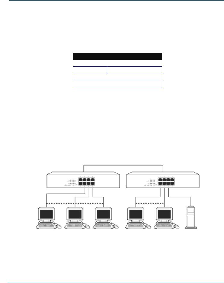
3.5 Typical Network Topology in Deployment
A hierarchical network with minimum switch levels may reduce the timing delay between server and client station. This will minimize the number of switches in any one path, lower the possibility of network loops, and improve network efficiency. If more than two switches are connected in the same network, select one switch as Level 1 switch and connect all other switches to it at Level 2. We recommend connecting the Server/Host to the Level 1 switch if no VLAN or other special requirements are used.
Case1: All switch ports are in the same local area network. Every port can access each other (See Figure 3-3).
Figure 3-3. No VLAN Configuration Diagram.
If VLAN is enabled and configured, each node in the network that can communicate each other directly is bound in the same VLAN area.
Here VLAN area is defined by what VLAN you are using. The switch supports both port-based VLAN and tag-based VLAN. They are different in practical deployment, especially in physical location. The following diagram shows how it works and what the differences are.
14 |
724-746-5500 l www.blackbox.com |
|
 Loading...