


LES401A
LES402A
LES404A
1-, 2-, and 4-Port Industrial Ethernet Serial Servers
Connect RS-232, RS-422, or RS-485 devices to an Ethernet network.
Access the serial ports over a LAN/WAN using Direct IP Mode, Virtual COM Port, or Paired Mode connections.
Customer
Support
Information
Order toll-free in the U.S.: Call 877-877-BBOX (outside U.S. call 724-746-5500)
FREE technical support 24 hours a day, 7 days a week: Call 724-746-5500 or fax 724-746-0746 Mailing address: Black Box Corporation, 1000 Park Drive, Lawrence, PA 15055-1018
Web site: www.blackbox.com • E-mail: info@blackbox.com

Trademarks Used in this Manual
Trademarks Used in this Manual
Black Box and the Double Diamond logo are registered trademarks of BB Technologies, Inc. VT100 is a trademark of Digital Equipment Corporation.
HyperTerminal is a registered trademark of Hilgraeve, Inc.
Internet Explorer, Microsoft, Windows, and Windows Vista are registered trademarks of Microsoft Corporation. Any other trademarks mentioned in this manual are acknowledged to be the property of the trademark owners.
We‘re here to help! If you have any questions about your application or our products, contact Black Box Tech Support at 724-746-5500 or go to blackbox.com and click on “Talk to Black Box.”
You’ll be live with one of our technical experts in less than 30 seconds.
Page 2 |
724-746-5500 | blackbox.com |

FCC and NOM Statement
Federal Communications Commission and Industry Canada Radio Frequency Interference
Statements
This equipment generates, uses, and can radiate radio-frequency energy, and if not installed and used properly, that is, in strict accordance with the manufacturer’s instructions, may cause interference to radio communication. It has been tested and found to comply with the limits for a Class A computing device in accordance with the specifications in Subpart B of Part 15 of FCC rules, which are designed to provide reasonable protection against such interference when the equipment is operated in a commercial environment. Operation of this equipment in a residential area is likely to cause interference, in which case the user at his own expense will be required to take whatever measures may be necessary to correct the interference.
Changes or modifications not expressly approved by the party responsible for compliance could void the user’s authority to operate the equipment.
This digital apparatus does not exceed the Class A limits for radio noise emission from digital apparatus set out in the Radio
Interference Regulation of Industry Canada.
Le présent appareil numérique n’émet pas de bruits radioélectriques dépassant les limites applicables aux appareils numériques de la classe A prescrites dans le Règlement sur le brouillage radioélectrique publié par Industrie Canada.
724-746-5500 | blackbox.com |
Page 3 |

NOM Statement
Instrucciones de Seguridad
(Normas Oficiales Mexicanas Electrical Safety Statement)
1.Todas las instrucciones de seguridad y operación deberán ser leídas antes de que el aparato eléctrico sea operado.
2.Las instrucciones de seguridad y operación deberán ser guardadas para referencia futura.
3.Todas las advertencias en el aparato eléctrico y en sus instrucciones de operación deben ser respetadas.
4.Todas las instrucciones de operación y uso deben ser seguidas.
5.El aparato eléctrico no deberá ser usado cerca del agua—por ejemplo, cerca de la tina de baño, lavabo, sótano mojado o cerca de una alberca, etc.
6.El aparato eléctrico debe ser usado únicamente con carritos o pedestales que sean recomendados por el fabricante.
7.El aparato eléctrico debe ser montado a la pared o al techo sólo como sea recomendado por el fabricante.
8.Servicio—El usuario no debe intentar dar servicio al equipo eléctrico más allá a lo descrito en las instrucciones de operación. Todo otro servicio deberá ser referido a personal de servicio calificado.
9.El aparato eléctrico debe ser situado de tal manera que su posición no interfiera su uso. La colocación del aparato eléctrico sobre una cama, sofá, alfombra o superficie similar puede bloquea la ventilación, no se debe colocar en libreros o gabinetes que impidan el flujo de aire por los orificios de ventilación.
10.El equipo eléctrico deber ser situado fuera del alcance de fuentes de calor como radiadores, registros de calor, estufas u otros aparatos (incluyendo amplificadores) que producen calor.
11.El aparato eléctrico deberá ser connectado a una fuente de poder sólo del tipo descrito en el instructivo de operación, o como se indique en el aparato.
12.Precaución debe ser tomada de tal manera que la tierra fisica y la polarización del equipo no sea eliminada.
13.Los cables de la fuente de poder deben ser guiados de tal manera que no sean pisados ni pellizcados por objetos colocados sobre o contra ellos, poniendo particular atención a los contactos y receptáculos donde salen del aparato.
14.El equipo eléctrico debe ser limpiado únicamente de acuerdo a las recomendaciones del fabricante.
15.En caso de existir, una antena externa deberá ser localizada lejos de las lineas de energia.
16.El cable de corriente deberá ser desconectado del cuando el equipo no sea usado por un largo periodo de tiempo.
17.Cuidado debe ser tomado de tal manera que objectos liquidos no sean derramados sobre la cubierta u orificios de ventilación.
18.Servicio por personal calificado deberá ser provisto cuando:
A:El cable de poder o el contacto ha sido dañado; u
B:Objectos han caído o líquido ha sido derramado dentro del aparato; o
C:El aparato ha sido expuesto a la lluvia; o
D:El aparato parece no operar normalmente o muestra un cambio en su desempeño; o
E:El aparato ha sido tirado o su cubierta ha sido dañada.
Page 4 |
724-746-5500 | blackbox.com |

Table of Contents
Table of Contents
Serial Server Quick Start Guide.............................................................................................................................................. |
7 |
|||
1. |
Specifications |
........................................................................................................................................................... |
10 |
|
|
1.1 |
General........................................................................................................................................................... |
10 |
|
|
1.2 |
Default Settings............................................................................................................................................... |
11 |
|
2. |
Overview |
........................................................................................................................................................... |
13 |
|
|
2.1 |
Introduction.................................................................................................................................................... |
13 |
|
|
|
2.1.1 |
Applications........................................................................................................................................ |
13 |
|
|
2.1.2 |
Manager Software............................................................................................................................. |
13 |
|
|
2.1.3 |
Monitor Port...................................................................................................................................... |
13 |
|
|
2.1.4 |
Web Server........................................................................................................................................ |
13 |
|
|
2.1.5 |
Heartbeat Connection Protection....................................................................................................... |
13 |
|
2.2 |
Features.......................................................................................................................................................... |
14 |
|
|
2.3 |
Communication Modes.................................................................................................................................. |
15 |
|
|
|
2.3.1 |
Direct IP Mode................................................................................................................................... |
15 |
|
|
2.3.2 |
Virtual COM Mode............................................................................................................................. |
15 |
|
|
2.3.3 |
Paired Mode....................................................................................................................................... |
16 |
|
|
2.3.4 |
Heartbeat........................................................................................................................................... |
16 |
|
2.4 |
What’s Included............................................................................................................................................. |
16 |
|
|
2.5 |
Hardware Description..................................................................................................................................... |
16 |
|
3. |
Hardware Configuration............................................................................................................................................. |
19 |
||
|
3.1 |
Serial Server Indicators, Switches, and Connectors......................................................................................... |
19 |
|
|
|
3.1.1 |
Indicators............................................................................................................................................ |
19 |
|
|
3.1.2 |
Switches............................................................................................................................................. |
19 |
|
|
3.1.3 |
Connectors......................................................................................................................................... |
19 |
|
3.2 |
Serial Server/Port Operational Modes............................................................................................................. |
20 |
|
|
|
3.2.1 |
Default Mode..................................................................................................................................... |
20 |
|
|
3.2.2 |
Console Mode.................................................................................................................................... |
20 |
|
|
3.2.3 |
Upgrade Mode................................................................................................................................... |
20 |
|
|
3.2.4 |
RS-232 Mode..................................................................................................................................... |
21 |
|
|
3.2.5 |
RS-422 Mode..................................................................................................................................... |
21 |
|
|
3.2.6 |
RS-485H Mode.................................................................................................................................. |
21 |
|
|
3.2.7 |
RS-485F Mode................................................................................................................................... |
21 |
|
|
3.2.8 |
RS-485 Receiver Biasing..................................................................................................................... |
21 |
4. |
Installing the Software............................................................................................................................................... |
24 |
||
|
4.1 |
Automatic Installation..................................................................................................................................... |
24 |
|
|
4.2 |
Manual Installation......................................................................................................................................... |
24 |
|
|
4.3 |
Updating an Existing Installation.................................................................................................................... |
26 |
|
|
4.4 |
Opening the Serial Server Manager Software................................................................................................ |
26 |
|
5. |
Using Serial Server Manager...................................................................................................................................... |
27 |
||
|
5.1 |
Hardware Setup............................................................................................................................................. |
27 |
|
|
5.2 |
Software Setup............................................................................................................................................... |
28 |
|
|
5.3 |
Software Overview......................................................................................................................................... |
29 |
|
|
|
5.3.1 |
Menus................................................................................................................................................ |
29 |
|
|
5.3.2 |
Server Icons Pane............................................................................................................................... |
30 |
|
|
5.3.3 |
Serial Server/Virtual COM Lists........................................................................................................... |
30 |
724-746-5500 | blackbox.com |
Page 5 |

Table of Contents
|
5.4 |
Search for Servers........................................................................................................................................... |
30 |
|
|
5.5 |
Configure Server Properties............................................................................................................................ |
31 |
|
6. |
Configuring the Serial Server Properties..................................................................................................................... |
32 |
||
7. |
Installing Virtual COM Ports....................................................................................................................................... |
38 |
||
|
7.1 |
Virtual COM Port Installation.......................................................................................................................... |
38 |
|
|
7.2 |
Matching the Serial Server and Virtual COM Port Settings............................................................................. |
40 |
|
8. |
Removing Virtual COM Ports..................................................................................................................................... |
42 |
||
|
8.1 |
Using Serial Server Manager........................................................................................................................... |
42 |
|
|
8.2 |
Using Device Manager.................................................................................................................................... |
42 |
|
9. |
Upgrading the Serial Server Firmware........................................................................................................................ |
45 |
||
|
9.1 |
Downloading the Firmware............................................................................................................................ |
45 |
|
|
9.2 |
Upgrading via Serial Server Manager.............................................................................................................. |
45 |
|
|
|
9.2.1 |
Preparing the Software...................................................................................................................... |
45 |
|
|
9.2.2 |
Upgrading the Firmware.................................................................................................................... |
45 |
10. |
Using Console Mode.................................................................................................................................................. |
47 |
||
11. |
Using the Web Server................................................................................................................................................ |
50 |
||
12. |
Using Telnet |
........................................................................................................................................................... |
53 |
|
Appendix A. RS-232 Connections....................................................................................................................................... |
55 |
|||
|
A.1 |
2- and 4-Port Serial Server DB9 Pinout in RS-232 Mode................................................................................ |
55 |
|
|
A.2 |
1-Port Serial Server Terminal Block Pinout in RS-232 Mode........................................................................... |
55 |
|
Appendix B. RS-422/485 Connections................................................................................................................................ |
56 |
|||
|
B.1 |
2-Port and 4-Port Serial Server DB9 Pinout in RS-422 Mode......................................................................... |
56 |
|
|
B.2 |
1-Port Serial Server Terminal Block Pinout in RS-422 Mode........................................................................... |
57 |
|
Appendix C. RS-485 Connections....................................................................................................................................... |
58 |
|||
|
C.1 |
1-, 2-, or 4-Port Serial Server DB9 Pinout in RS-485H (Two-Wire, Half-Duplex) Mode................................... |
58 |
|
|
C.2 |
1-, 2-, or 4-Port Serial Server DB9 Pinout in RS-485F (Four-Wire, Full-Duplex) Mode.................................... |
58 |
|
|
C.3 |
1-Port Serial Server Terminal Block Pinout in RS-485F (Four-Wire, Full-Duplex) Mode................................... |
59 |
|
Appendix D. Network Connections..................................................................................................................................... |
60 |
|||
|
D.1 |
Standard Ethernet Cable RJ-45 Pinout........................................................................................................... |
60 |
|
|
D.2 |
Crossover Ethernet Cable RJ-45 Pinout.......................................................................................................... |
61 |
|
Page 6 |
724-746-5500 | blackbox.com |
Quick Start Guide
Quick Start Guide
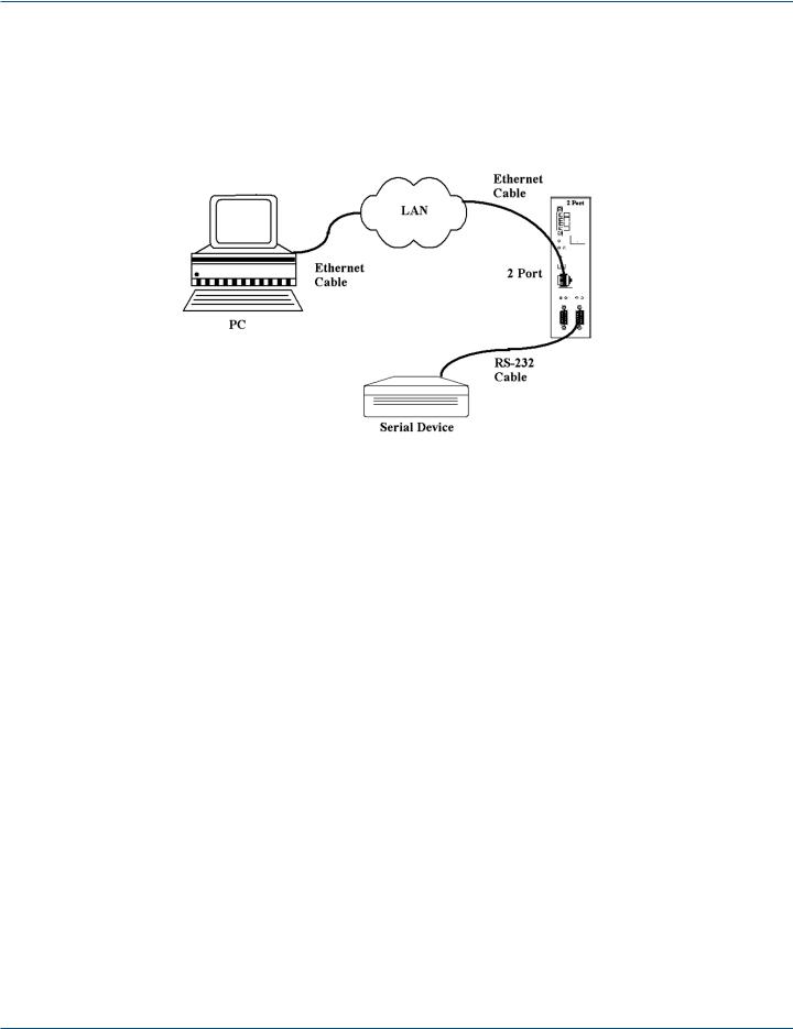
For descriptive purposes, this Quick Start Guide considers a typical configuration consisting of a PC connected via an Ethernet LAN to a 2-Port Industrial Serial Server connected to the RS-232 port of a serial device.
Hardware Setup
Figure QS-1. Typical hardware setup.
Step 1: Connect the Serial Server to the network using a standard network cable.
Step 2: Connect the Serial Server to the RS-232 port on the serial device.
NOTE: If the serial device is configured as a DCE, use a straight-through serial cable. If the serial device is configured as a DTE, use a crossover (null-modem) cable.
Step 3: Set the Run/Console DIP switch to the Run position.
Step 4: Apply power to the Serial Server.
Software Installation
Using the CD included with the serial server, install the Serial Server Manager software on the configuring computer.
Serial Server Configuration
Step 1: Open the Serial Server Manager software. It will automatically search for any reachable Serial Servers. A list of all Serial Servers connected to the LAN will appear in the Serial Server List window.
Step 2: Double-click the desired Serial Server port on the list to bring up the Server Properties configuration screen.
724-746-5500 | blackbox.com |
Page 7 |
Quick Start Guide
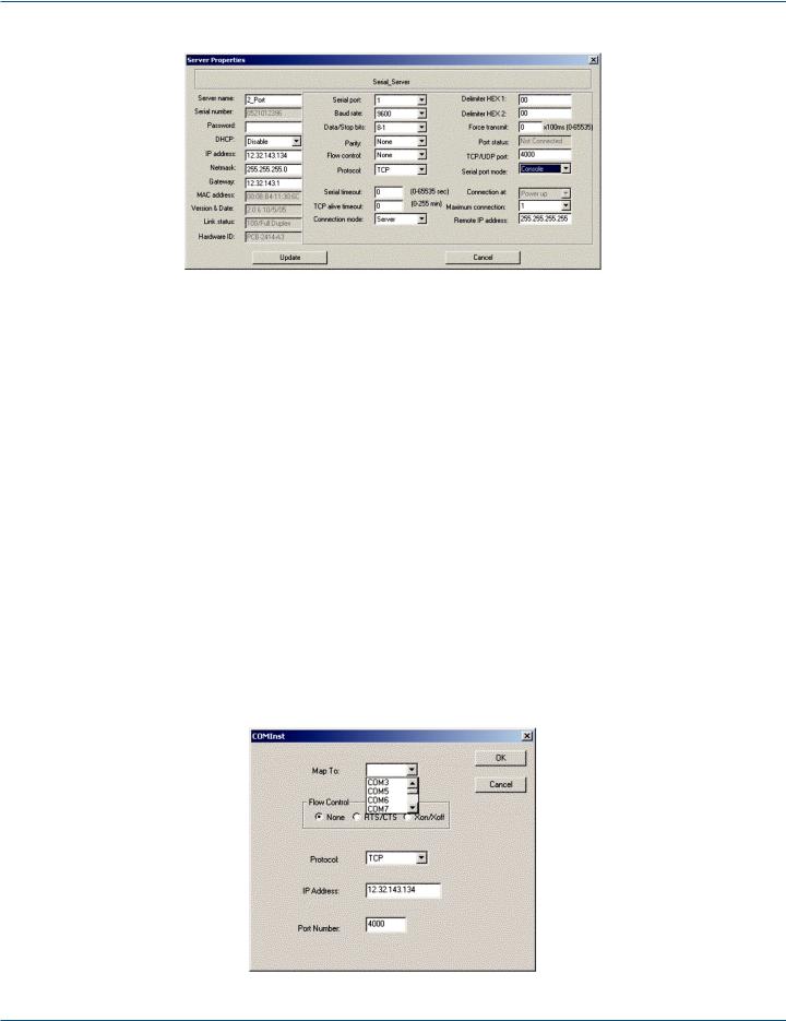
Figure QS-2. The Server Properties window.
Step 3: Change the Server Properties as required.
• Enable DHCP to allow the Serial Server to generate its own IP address
OR
•Obtain appropriate static IP, netmask, and gateway addresses from your Network Administrator (recommended).
•Set the Serial Port Mode property to RS-232 to match the serial device connected to the Serial Server.
•Set Baud Rate, Data/Parity/Stop, and Flow Control to match the configuration of the serial device connected to the Serial Server port.
Step 4: When the parameters have been set, click “Update.” Following the prompts in the dialog boxes, Restart the Serial Server and Search all reachable servers again.
Step 5: Re-enter Server Properties to verify the changes have taken effect, or to view/change the configuration of other ports. Each port must be configured separately.
Install Virtual COM Ports on PC
Step 1: From the Windows Start menu, run the Install Virtual COM Ports utility included with the Serial Server Manager software,
Step 2: Search for all servers on the network
Step 3: Select a port and map it to an unused COM port (for example, Port 15). Configure it for TCP protocol and the appropriate IP address (determined in the last section).
Figure QS-3. Configuring the Virtual COM Port.
Page 8 |
724-746-5500 | blackbox.com |

Quick Start Guide
Check Communications
Step 1: From the Windows Start menu, run HyperTerminal.
Step 2: Configure HyperTerminal to connect using the COM port configured in the last section (for example, Port 15).
Step 3: Set Baud Rate, Data/Parity/Stop, and Flow Control to match the configuration of the serial device connected to the Serial Server serial port.
Step 4: Communications with the serial device should now be operational.
724-746-5500 | blackbox.com |
Page 9 |

Chapter 1: Specifications
1. Specifications
1.1 General
Approvals — FCC, IP30 case
Configuration Options — Console mode: Using RS-232 with VT100™ emulation; Telnet mode: Using HyperTerminal with VT100 emulation;
Serial Server Manager: Windows® 98/ME/2000/2003 Server/XP, Windows NT, Windows Vista®; Web server: Using Internet Explorer® Web browser
Data Rate — 110 bps to 230.4 kbps
I/P Port Addresses — 5300: Heartbeat and Configuration setting in TCP mode (that is, Pair mode); 8888: Serial server update;
8890: Serial server monitor;
8889: Set configuration in UDP mode
Management — Manager, Web Server, Serial Console, Telnet
Memory — Serial: 8 KB per port;
Network: 48 KB
Network Communications — LAN: 10-/100-Mbps Autodetecting 10BASE-T, 100BASE-TX; RS-232: TX, RX, RTS, CTS, DTR, DSR, DCD, GND;
RS-422: TX+, TX-, RX+, RX-, RTS+, RTS-, CTS+, CTS-, GND; RS-485H: Data+, Data-, GND;
RS-485F: TX+, TX-, RX+, RX-, GND
Operating System — Windows 2000, 2003 Server/XP, 2008, Windows Vista, Windows 7
Optional Accessories — (1) null-modem crossover cable for DTE-to-DTE connection;
(1) 3.2-ft. [1-m] 35-mm steel DIN rail
Protocols — TCP, IP, ARP, DHCP, Telnet, HTTP, UDP, ICMP
Serial Interfaces — RS-232 (DTE): TXD, RXD, RTS, CTS, DTR, DSR, DCD, GND; Terminal block (LES401A only): TXD, RXD, RTS, CTS, GND;
RS-422: TXDB(+), TXDA(-), RXDB(+), RXDA(-), RTS(+), RTS(-), CTS(+), CTS(-), GND; RS-485H: Data B(+), Data A(-) and GND;
RS-485F: TXDB(+), TXDA(-), RXDB(+), RXDA(-), GD; Baud Rate: 110 bps to 230.4 bps
Parity: None, Even, Odd, Mark, Space Data Bits: 5, 6, 7, or 8
Stop Bits: 1, 1.5, or 2
User Controls — LES401A: (1) DB9/terminal block switch
Connectors — LES401A: (1) 4-pin terminal block (removable) for DC power, (1) DB9 male, (1) RJ-45 for Ethernet; LES402A: (2) DB9 male, (1) RJ-45 for Ethernet;
LES404A: (4) DB9 male, (1) RJ-45 for Ethernet
Indicators — Power: Red LED, Link: Yellow or green LED (10BASE-T or 100BASE-TX), Ready: Flashing green LED
Temperature Tolerance — Operating: +14 to +176° F (-10 to +80° C);
Storage: -4 to +185° F (-20 to +85° C)
Relative Humidity — 5 to 98%
Page 10 |
724-746-5500 | blackbox.com |
Chapter 1: Specifications
Power Requirements — 8 VAC to 24 VAC or 9 VDC to 48 VDC Power consumption: LES401A: 320 mA @ 12 VDC,
LES402A: 340 mA @ 12VDC, LES404A: 360 mA @ 12 VDC; Power supply start-up time: ≤24 ms
Power connector: Terminal block
Size — 1.75"H x 6.1"W x 4.1"D (4.46 x 15.52 x 10.46 cm)
1.2 Default Settings
Baud Rate — 9600
Data/Stop — 8–1 Delimiter HEX 1 — 00 Delimiter HEX 2 — 00
DHCP — Disable
DIP Switch Settings — 1-Port Serial Server: 1=Run, 2=DB9; 2- or 4-Port Serial Server: Run
Flow Control — None Force Transmit — 0 ms
Gateway — 192.168.0.254
IP Address — 192.168.0.1
MAC Address — Fixed (see bottom label on unit)
Maximum Connection — 1
Net Mask — 255.255.255.0
Password — Blank Parity — None
Server Name — 1_Port, 2_Port, or 4_Port
Serial Number — xxxxxxxxx (printed on bottom of unit)
Serial Port Mode — RS-232 Serial Server Port — 1 Serial Timeout — 0 seconds
TCP alive timeout — 0 minutes
TCP/UDP Port — Port 1: 4000; Port 2: 4001;
Port 3: 4002;
Port 4: 4003
Remote IP Address — 255.255.255.255 RS-232 Connection Mode — Server
TCP/UDP Protocol — 1-Port Serial Server Port 1: TCP; 2-Port Serial Server Ports 1 and 2: TCP;
4-Port Serial Server Ports 1–4: TCP
Version and Date — Current firmware version number and date
724-746-5500 | blackbox.com |
Page 11 |
Chapter 1: Specifications
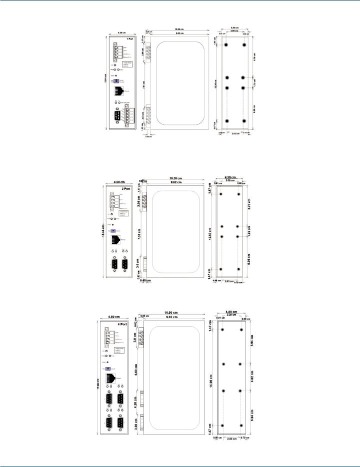
Figure 1-1. 1-Port Serial Server dimensions.
Figure 1-2. 2-Port Serial Server dimensions.
Figure 1-3. 4-Port Serial Server dimensions.
Page 12 |
724-746-5500 | blackbox.com |

Chapter 2: Overview
2. Overview
2.1 Introduction
1-, 2-, and 4-Port Port Industrial Ethernet Serial Servers enable connection of RS-232, RS-422, or RS-485 devices to an Ethernet network. You can access the serial ports over a LAN/WAN using Direct IP Mode, Virtual COM Port, or Paired Mode connections. The 10-/100-Mbps Ethernet connection auto-selects 10BASE-T or 100BASE-TX and indicates the type of connection with a bi-color link light. These serial servers are built for use in industrial environments, featuring an IP30-approved, slim-line, DIN-rail-mountable case. They operate from a range of AC or DC power supply voltages, support redundant DC power, and feature terminal block power connectors.
Industrial and commercial measurement and control systems often have standalone devices with unused serial ports. Black Box® Serial Servers allow you to connect those ports into your existing LAN or WAN, giving you access to more information and the ability to configure, manage, and troubleshoot those devices from a control room, office, or even a distant location via a WAN. Save the cost, time and trouble of carrying a laptop out to devices located in distant, cold, dirty, or uncomfortable environments.
Connect your serial device to the serial port and connect the server to your LAN. Your networked computer “sees” the device over the network as a virtual serial connection. Black Box serial servers support TCP or UDP protocols and allow transmitting to and receiving from multiple IP addresses. There are four methods of configuring serial servers: via Management Software, Web Server, Telnet, or via a direct RS-232 console connection using a terminal program.
2.1.1 Applications
•Access remote devices with serial ports via your network.
•Manage, configure, and program devices remotely via a Web server.
•Use for industrial devices such as PLCs, drives, motor controls, process analyzers.
•Building/commercial/security—parking control, security, cameras.
•Traffic management—lights, systems, cameras.
•Retail/point of sale—cash registers, scanners, scales.
2.1.2 Manager Software
The Manager software allows easy access to the serial server to configure the server and its ports, upgrade server firmware, and monitor port status and activity. When the Manager opens, it will search for and display all serial servers on the network.
2.1.3 Monitor Port
The Monitor Port feature allows you to use any PC on the LAN/WAN to actively view and troubleshoot the communications status. It shows when there is a client connection to the server and the client IP address. It displays the number of bytes transmitted and received as well as the status of the hardware handshaking lines.
2.1.4 Web Server
Black Box serial servers can be accessed and configured from any Web browser (such as Internet Explorer) on the LAN/WAN. This allows you to remotely manage the software and your serial device. It also allows off-site troubleshooting.
2.1.5 Heartbeat Connection Protection
LES400A series Serial Servers provide automatic resumption of the TCP data connection in case of a power failure or loss of an Ethernet connection on either the client or server. Once the Heartbeat connection is established, the server sends a signal to the client every five seconds until communication is re-established. Without this feature, a device that loses a connection and stops communicating would not be able to reconnect without a person attending to the problem. The Heartbeat feature works with virtual COM and TCP direct IP connections.
724-746-5500 | blackbox.com |
Page 13 |
Chapter 2: Overview
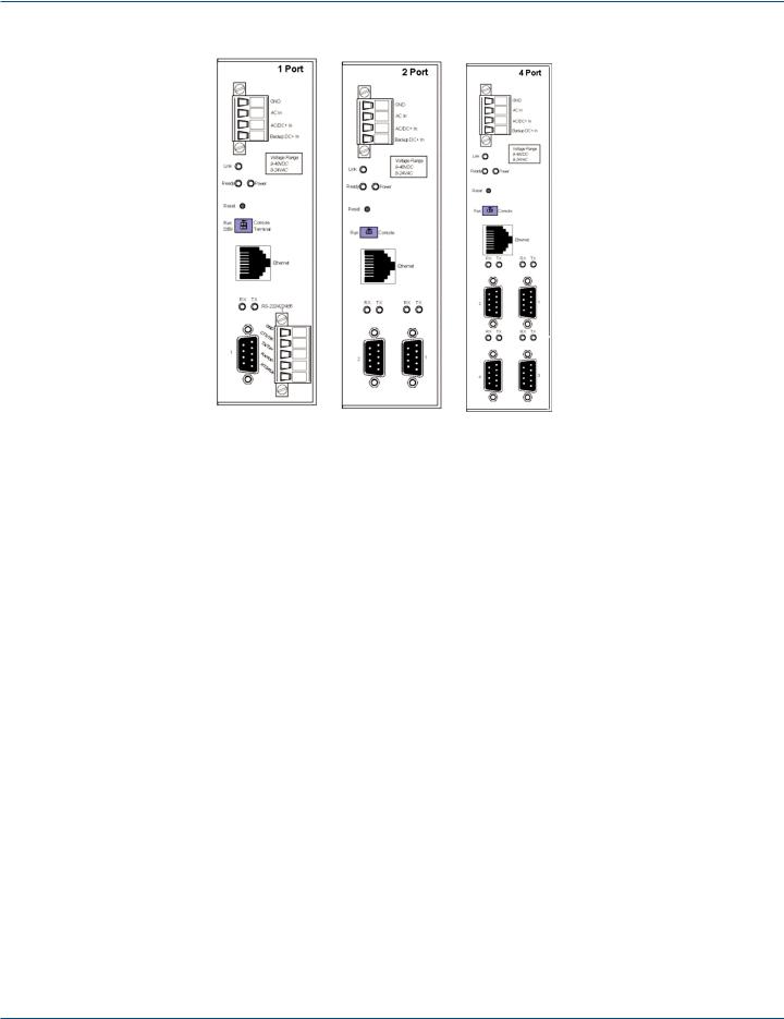
Figure 2-1. 1-, 2-, and 4-Port Industrial Serial Servers.
2.2 Features
•Multi-interface serial ports: The 1-Port Industrial Serial Server features one multi-interface serial port and the choice of standard
DB9 M or removable terminal block connections (switch selectable).
The 2-Port Industrial Serial Server features two multi-interface serial ports.
The 4-Port Industrial Serial Server features four multi-interface serial ports.
All ports are software selectable as RS-232, RS-422, RS-485 half-duplex, or RS-485 full-duplex interfaces.
For all models Port 1 is software, or DIP switch selectable for Console Mode operation (configuration via direct serial connection).
•Slim-line, DIN-rail-mountable case.
•Accepts AC or DC power over a wide voltage range.
•Redundant DC power supply input.
•10-/100-Mbps Ethernet with Auto Selection.
•LAN and WAN communications.
•TCP or UDP client or server operation—configurable.
•Software support—2000/2003 Server/XP/Vista/2008/Windows 7.
•Firmware upload for future revisions/upgrades.
•Can be accessed and configured via a Web browser using Web Server.
•Supports RS-232, RS-422, and RS-485 halfand full-duplex serial interfaces.
•Terminal block power connectors for industrial installations.
•LES401A has a terminal block and a DB9 serial connector.
•In Server mode, supports eight individual client sessions.
Page 14 |
724-746-5500 | blackbox.com |

Chapter 2: Overview
•UDP mode allows broadcast to and from multiple IP addresses.
•Management access password protected.
•Configure the Ethernet and serial port settings using any of four methods:
1.Serial Server Manager Software for Windows enables configuration via a network connection or directly from the Ethernet port of a computer (using an Ethernet crossover cable).
2.Web Server enables configuration via the network using a Web browser.
3.Telnet enables configuration via the network by accessing the setup configuration menu.
4.Console Mode enables configuration through an RS-232 serial port in using a VT100 Terminal Emulation program and an RS-232 crossover cable.
•Virtual COM Driver Software for Windows for 2000/2003 Server/XP/Windows Vista/2008/Windows 7—installs virtual COM ports, viewable in the Windows Device Manager under Ports (COM & LPT). A Virtual COM port provides access to any of the ports on the Serial Server, like any other serial port (legacy, PCI, USB or PCMCIA) on the computer. Any program running on the computer and using Windows based COM ports can access the serial devices attached to the serial server. The LAN becomes transparent to the serial device and the software running on the PC.
•Heartbeat Connection—selectable protocol ensures reliable communications in Virtual COM Port or Paired Connection modes.
This feature restores the connections if communications are temporarily lost at either end because of loss of power or loss of the Ethernet connection.
2.3 Communication Modes
The Serial Servers enable communication with serial devices over a LAN or WAN. Serial devices no longer are limited to a physical connection to the PC COM port. They can be installed anywhere on the LAN using TCP/IP or UDP/IP communications. This enables traditional Windows PC software access to serial devices anywhere on the LAN/WAN network.
2.3.1 Direct IP Mode
Direct IP connections allow applications using TCP/IP or UDP/IP socket programs to communicate with the asynchronous serial ports on the serial server. In this type of application, the serial server is configured as a TCP or UDP server. The socket program running on the PC establishes a communication connection with the Serial Server. The data is sent directly to and from the serial port on the server. When using UDP protocol, the server can be configured to broadcast data to and receive data from multiple IP addresses.
2.3.2 Virtual COM Mode
Install Virtual COM Mode enables the user to add a driver to provide a virtual COM port on the computer. The new COM port shows up in the Device Manager. Windows programs using standard Windows API calls are able to interface to virtual COM ports. When a program on the PC opens the new COM port, it communicates with the remote serial device connected to one of the ports on the Serial Server.
After connection, the LAN is transparent to the program and serial device. Applications are able to work just as if the serial device is connected directly to a physical COM port on the computer. The virtual COM port software converts the application’s data into IP packets, sends it across the network to the Serial Server, which converts the IP packet back to serial data and sends the data out a serial port located on the Serial Server.
To use this mode, the Serial Server must be set to either TCP/server or UDP/server with a designated communication port number. The virtual COM driver is the TCP or UDP client.
724-746-5500 | blackbox.com |
Page 15 |
Chapter 2: Overview
2.3.3 Paired Mode
Paired Mode is also called serial tunneling. In this mode, any two serial devices that can communicate with a serial link will be able to communicate using two Serial Servers and the LAN.
Two Serial Servers are connected to a network, one configured as a TCP or UDP client and the other as a TCP/UDP server. When setting up the server the remote IP address section must contain the address of the client. This will allow the client’s IP address to pass the IP address-filtering feature of the server. Conversely, the Remote IP address of the client must contain the server’s IP address. Both communication port numbers must be the same.
2.3.4 Heartbeat
The Heartbeat protocol connection provides a reliable communications connection in Virtual COM Port Mode or with Paired Connection Mode. This feature restores the connection if communications are temporarily lost at either end because of loss of power or Ethernet connection.
Without this feature, a device that loses a connection and stops communicating would not be able to reconnect without human intervention. A TCP data connection can be lost when there is a power failure or temporary loss of an Ethernet connection on either the client or server. If a loss occurs, the Heartbeat feature will try to reconnect the TCP data connection every five seconds until communications are established again. The Heartbeat feature is available for use in Virtual COM Port Mode and Paired Connection Mode. This is not available when using a UDP application.
2.4 What’s Included
Your package should contain the following items. If anything is missing or damaged, contact Black Box Technical Support at 724-746-5500 or info@blackbox.com.
•1-, 2-, or 4-Port Industrial Serial Server module.
•(1) CD-ROM containing Serial Server Manager and Virtual COM Driver software for Windows 2000/2003 Server/XP/
Vista/2008/Win 7 and this user manual in PDF format.
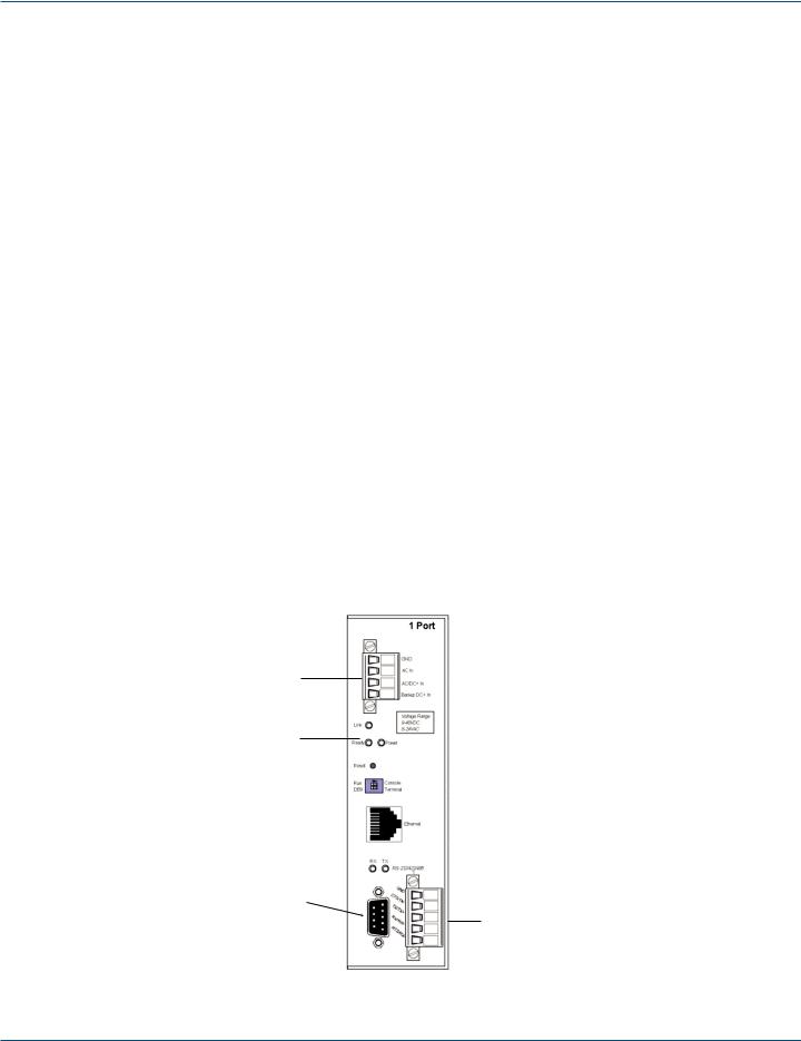
2.5 Hardware Description
Figure 2-2 shows the 1-Port Serial Server. Table 2-1 describes its components.
1
2
3
4 
5 
6 
7 
8 
9 
10
11
Figure 2-2. 1-Port Serial Server.
Page 16 |
724-746-5500 | blackbox.com |
Chapter 2: Overview
Table 2-1. 1-Port Serial Server components.
Number |
Component |
Description |
|
|
|
|
|
1 |
(1) terminal block connector |
Used for DC power. |
|
|
|
|
|
2 |
(1) |
Link LED |
Lights yellow for 10BASE-T or green for 100BASE-TX. |
|
|
|
|
3 |
(1) |
Ready LED |
Flashes green when the unit is ready to transmit/receive data. |
|
|
|
|
4 |
(1) |
Power LED |
Lights when power to the unit is on. |
|
|
|
|
5 |
(1) |
Reset button |
Press to reset the unit. |
|
|
|
|
6 |
(1) |
2-position DIP switch |
Selects run or console mode. |
|
|
|
|
7 |
(1) |
RJ-45 Ethernet connector |
Connects to Ethernet. |
|
|
|
|
8 |
(1) |
RX LED |
Lights when data is being received. |
|
|
|
|
9 |
(1) |
TX LED |
Lights when data is being transmitted. |
|
|
|
|
10 |
(1) |
DB9 connector |
Connects to serial device. |
|
|
|
|
11 |
(1) terminal block connector |
Links to serial device. |
|
|
|
|
|
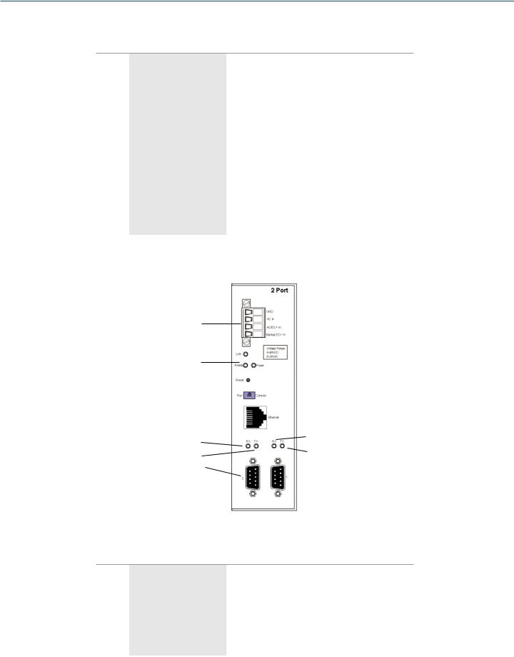
Figure 2-3 shows the 2-Port Serial Server. Table 2-2 describes its components.
1
2 
3
4 
5 
6 
7 
8 |
8 |
||
9 |
|||
9 |
|||
|
|
||
10 |
|
10 |
|
|
|
||
|
|
||
Figure 2-3. 2-Port Serial Server.
Table 2-2. 2-Port Serial Server components.
|
Number |
Component |
Description |
|
|
|
|
|
|
|
|
|
1 |
(1) terminal block connector |
Used for DC power. |
|
|
|
|
|
|
|
|
|
2 |
(1) |
Link LED |
Lights yellow for 10BASE-T or green for 100BASE-TX. |
|
|
|
|
|
|
|
|
3 |
(1) |
Ready LED |
Flashes green when the unit is ready to transmit/receive data. |
|
|
|
|
|
|
|
|
4 |
(1) |
Power LED |
Lights when power to the unit is on. |
|
|
|
|
|
|
|
|
5 |
(1) |
Reset button |
Press to reset the unit. |
|
|
|
|
|
|
|
|
|
|
|
|
|
724-746-5500 | blackbox.com |
Page 17 |
Chapter 2: Overview
Table 2-2 (Continued). 2-Port Serial Server components.
Number |
Component |
Description |
|
|
|
|
|
6 |
(1) |
2-position DIP switch |
Selects run or console mode. |
|
|
|
|
7 |
(1) |
RJ-45 Ethernet connector |
Connects to Ethernet. |
|
|
|
|
8 |
(2) |
RX LEDs |
Light when data is being received at the serial ports. |
|
|
|
|
9 |
(2) |
TX LEDs |
Light when data is being transmitted from the serial ports. |
|
|
|
|
10 |
(2) |
DB9 connectors |
Connect to serial devices. |
|
|
|
|
1 |
|
|
|
|
|
||
2 |
|
|
|
3 |
|
|
|
4 |
|
|
|
5 |
|
|
|
6 |
|
8 |
|
7 |
|
||
|
|
||
8 |
|
9 |
|
9 |
|
10 |
|
10 |
|||
9 |
|||
|
|
||
8 |
|
8 |
|
9 |
|
|
|
10 |
|
10 |
|
||
|
|
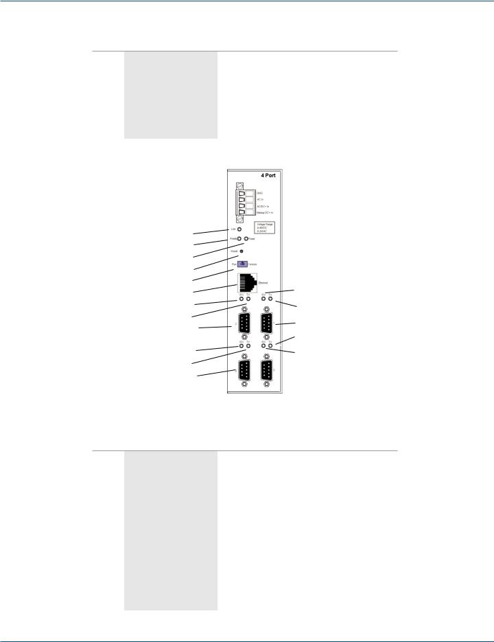
Figure 2-4. 4-Port Serial Server.
Table 2-3. 4-Port Serial Server components.
Number |
Component |
Description |
|
|
|
|
|
1 |
(1) terminal block connector |
Used for DC power. |
|
|
|
|
|
2 |
(1) |
Link LED |
Lights yellow for 10BASE-T or green for 100BASE-TX. |
|
|
|
|
3 |
(1) |
Ready LED |
Flashes green when the unit is ready to transmit/receive data. |
|
|
|
|
4 |
(1) |
Power LED |
Lights when power to the unit is on. |
|
|
|
|
5 |
(1) |
Reset button |
Press to reset the unit. |
|
|
|
|
6 |
(1) |
2-position DIP switch |
Selects run or console mode. |
|
|
|
|
7 |
(1) |
RJ-45 Ethernet connector |
Connects to Ethernet. |
|
|
|
|
8 |
(4) |
RX LEDs |
Light when data is being received at the serial ports. |
|
|
|
|
9 |
(4) TX LEDs |
Light when data is being transmitted from the serial ports. |
|
|
|
|
|
10 |
(4) DB9 connectors |
Connect to serial devices. |
|
|
|
|
|
Page 18 |
724-746-5500 | blackbox.com |

Chapter 3: Hardware Configuration
3. Hardware Configuration
3.1 Serial Server Indicators, Switches, and Connectors
3.1.1 Indicators
•One bi-color Link LED (Yellow = 10BASE-T, Green = 100BASE-T)
•One green Ready LED (flashing = system ready)
•One red Power LED
•One red RX LED and one green TX LED for each serial port
3.1.2 Switches
Reset
A recessed reset switch that enables the unit to be reset. Insert a small plastic tool, press lightly and hold for three seconds. The Link and Ready lights will go out and then come back on.
Run/Console Switch
A recessed single DIP (dual inline package) switch that allows the Serial Server to be switched between Run Mode and Console Mode. When switched to the Console position, the Serial Server enters Console Mode. This allows you to configure the Serial Server from a PC running a terminal program, such as HyperTerminal®, without connecting the server to the network. To communicate with the connected serial device, the switch must be returned to the “Run” position.
DB9/Terminal Switch (1-Port Industrial Serial Server only)
Allows connection to the serial port (RS-232, 422 or 485) via the DB9 M connector or the five-terminal removable terminal block.
3.1.3 Connectors
Ethernet Connector
One standard RJ-45 receptacle that allows the Serial Server to be connected to an Ethernet hub, switch, or wallplate using a standard straight-through RJ-45 (male) Ethernet cable. To connect directly to an RJ-45 Ethernet port on a PC or laptop, a crossover Ethernet cable must be used.
Serial Port(s)
•1-Port Industrial Serial Server: (1) serial port with (2) connector options: (1) (DB9 M) or (1) five-terminal removable terminal block
(DIP switch selectable)
•2-Port Industrial Serial Server: (2) serial port connectors (DB9 M)
•4-Port Industrial Serial Server: (4) serial port connector (DB9 M)
NOTE: Refer to Appendixes A, B, and C for connection pinouts.
724-746-5500 | blackbox.com |
Page 19 |

Chapter 3: Hardware Configuration
Power Connector
The power connector is a removable terminal block with four terminals. From top to bottom the terminals are:
Table 3-1. Power connector.
Terminal |
Connect to |
Description |
|
|
|
Negative side of DC power supply (if DC
power used).
GND
Also connect negative side of backup DC power supply (if used).
Internally, the chassis ground of the serial server is connected to this terminal.
AC in |
One side of AC power supply (if AC power |
|
used) |
||
|
||
|
|
|
|
The other side of AC power supply (if AC |
|
|
power used) |
Either AC or DC power can be used to power serial servers. The power supply voltages can range from 9 VDC to 48 VDC or 8 VAC to 24 VAC.
AC/DC+ in |
OR |
|
|
|
Positive side of DC power supply (if DC |
|
|
|
power used) |
|
|
|
|
|
|
Backup DC+ in |
Positive side of backup DC power supply |
Backup power must be DC voltage and can be any voltage between 9 VDC and |
|
48 VDC. |
|||
|
|
||
|
|
|
3.2 Serial Server/Port Operational Modes
Using the Serial Server Manager, Web Server, or Telnet, the Serial Server can be put into Console Mode, Default Mode, or Upgrade Mode. The serial ports can be configured for RS-232, RS-422, RS-485H (half-duplex), or RS-485F (full-duplex) operation. The server also can be put into Console Mode by placing the Run/Console switch in the Console position.
3.2.1 Default Mode
When Default Mode is selected and the server properties are Updated (Saved), all the configuration settings return to their default values.
NOTE: Refer to Chapter 6 for details on Serial Server Configuration settings. See Chapter 1 for Serial Server default parameters.
3.2.2 Console Mode
In Console Mode, the Configuration Menu can be accessed from a PC by connecting its RS-232 serial port to the 1-Port Industrial Serial Server serial port or 2- or 4-Port Industrial Serial Server Serial Port 1. Since the computer is a DTE device and the serial ports are configured as DTEs (with DB9 M connectors), a null-modem crossover cable must be used.
In Console Mode, the default serial port settings are: 9600 baud, 8 data bits, no parity, and 1 stop bit. From Windows, HyperTerminal with VT100 terminal emulation can be used for Console Mode configuration.
NOTE: Refer to Chapter 10 for details on Console Mode.
3.2.3 Upgrade Mode
In Upgrade Mode, firmware can be uploaded from a PC via its serial port to the 1-Port Industrial Serial Server serial port or the 2-port or 4-Port Industrial Serial Server Serial Port 1. Upgrading also can be done via the network connection, using the Serial Server Manager software and a virtual COM port.
NOTE: Refer to Chapter 9 for details on Upgrade Mode.
Page 20 |
724-746-5500 | blackbox.com |
 Loading...