


DW900,DW901/383609 bc 5/8/02 2:59 PM Page 2
DEWALT Industrial Tool Co., 701 East Joppa Road, Baltimore, MD 21286 Printed in U.S.A. (XXX00-CD-1) Form No. 383609-01 DW900, DW901 Copyright © 2002
The following are trademarks for one or more DeWALT power tools: the yellow and black color scheme; the “D” shaped air intake rill;g the array of pyramids on the handgrip; the kit box configuration; and the array of lozenge-shaped humps on the surface of the tool.

DW900,DW901/383609 bc 5/8/02 2:59 PM Page 3
INSTRUCTION MANUAL GUIDE D'UTILISATION MANUAL DE INSTRUCCIONES
INSTRUCTIVO DE OPERACIÓN, CENTROS DE SERVICIO Y PÓLIZA DE GARANTÍA.ADVERTENCIA: LÉASE ESTE INSTRUCTIVO ANTES DE USAR EL PRODUCTO.
DW900/DW901
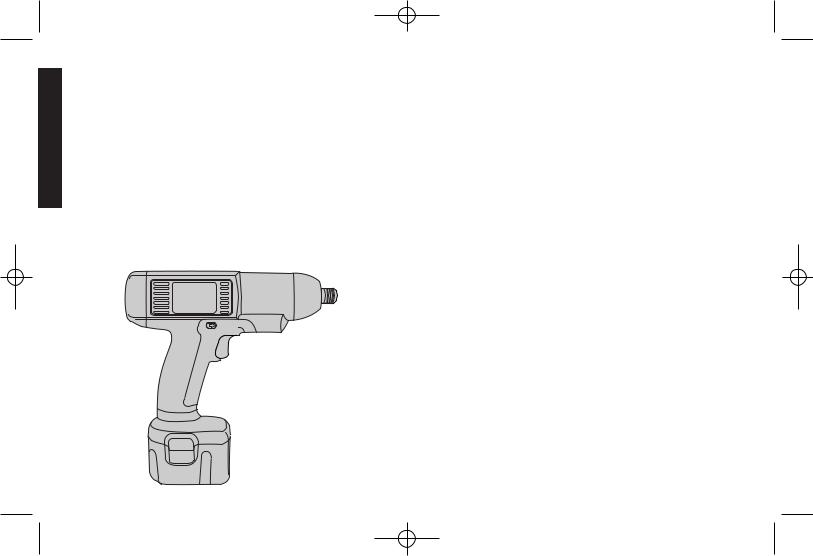
Precision Torque Screwdriver Tournevis dynamométrique Destornillador con par de precisión
DW900,DW901/383609 bc 5/8/02 2:59 PM Page 4
English
Introduction
Thank you for purchasing the DEWALT Precision Torque Screwdriver. The Precision Torque Screwdriver has been designed for maximum productivity: its precise torque control, ease of operation and cordless convenience make it ideal for almost any fastening task. Its quiet, oil-free operation and ergonomicically enhanced design make it ideal for almost any line worker. The Precision Torque Screwdriver provides these benefits without the drawbacks of air tools.
IF YOU HAVE ANY QUESTIONS OR COMMENTS ABOUT THIS OR ANY DEWALT TOOL, CALL US TOLL FREE AT:
1-800-4-DEWALT (1-800-433-9258)
Important Safety Instructions
 WARNING: When using electric tools, basic safety precautions should always be followed to reduce risk of fire, electric shock, and personal injury, including the following:
READ ALL INSTRUCTIONS
•KEEP WORK AREA CLEAN. Cluttered areas and benches invite injuries.
•CONSIDER WORK AREA ENVIRONMENT. Don’t expose power tools to rain. Don’t use power tools in damp or wet locations. Keep work area well lit. Do not use tool in presence of flammable liquids or gases.
•GUARD AGAINST ELECTRIC SHOCK. Prevent body contact with grounded surfaces. For example; pipes, radiators, ranges, and refrigerator enclosures.
•KEEP CHILDREN AWAY. Do not let visitors contact tool or extension cord. All visitors should be kept away from work area.
•STORE IDLE TOOLS. When not in use, tools should be stored in dry, and high or locked-up place — out of reach of children.
•DON’T FORCE TOOL. It will do the job better and safer at the rate for which it was intended.
•USE RIGHT TOOL. Don’t force small tool or attachment to do the job of a heavy-duty tool. Don’t use tool for purpose not intended.
•DRESS PROPERLY. Do not wear loose clothing or jewelry. They can be caught in moving parts. Rubber gloves and non-skid footwear are recommended when working outdoors. Wear protective hair covering to contain long hair. Air vents often cover moving parts and should also be avoided.
•USE SAFETY GLASSES. Also use face or dust mask if operation is dusty.
•SECURE WORK. Use clamps or a vise to hold work. It’s safer than using your hand and it frees both hands to operate tool.
•DON’T OVERREACH. Keep proper footing and balance at all times.
DW900,DW901/383609 bc 5/8/02 2:59 PM Page 1
•MAINTAIN TOOLS WITH CARE. Keep tools sharp and clean for better and safer performance. Follow instructions for lubricating and changing accessories. Inspect tool cords periodically and if damaged, have repaired by authorized service facility. Inspect extension cords periodically and replace if damaged. Keep handles dry, clean, and free from oil and grease.
•REMOVE ADJUSTING KEYS AND WRENCHES. Form habit of checking to see that keys and adjusting wrenches are removed from tool before turning it on.
•DISCONNECT OR LOCK OFF TOOLS when not in use, before servicing, and when changing accessories, such as blades, bits, cutters.
•AVOID UNINTENTIONAL STARTING. Don’t carry tool with finger on switch
•STAY ALERT. Watch what you are doing. Use common sense. Do not operate tool when you are tired.
•CHECK DAMAGED PARTS. Before further use of the tool, a guard or other part that is damaged should be carefully checked to determine that it will operate properly and perform its intended function. Check for alignment of moving parts, binding of moving parts, breakage of parts, mounting, and any other conditions that may affect its operation. A guard or other part that is damaged should be properly repaired or replaced by an authorized service center unless otherwise indicated elsewhere in this instruction manual. Have defective switches replaced by authorized service center. Do not use tool if switch does not turn it on and off.
• CAUTION: When fastening into walls, floors or wherever live electrical wires may be encountered, DO NOT TOUCH ANY METAL PARTS OF THE TOOL! Hold the tool only by insulated grasping surfaces to prevent electric shock if you drill or drive into a live wire.
• CAUTION: Remove battery pack before adjusting tool torque setting.
 CAUTION: Some tools with large battery packs will stand upright on the battery pack but may be easily knocked over. When not in use,
1
place tool on its side on a stable surface where it will not cause a tripping or falling hazard.
 WARNING: Some dust created by power sanding, sawing, grinding, drilling, and other construction activities contains chemicals known to cause cancer, birth defects or other reproductive harm. Some examples of these chemicals are:
•lead from lead-based paints,
•crystalline silica from bricks and cement and other masonry products, and
•arsenic and chromium from chemically-treated lumber (CCA).
Your risk from these exposures varies, depending on how often you do this type of work. To reduce your exposure to these chemicals: work in a well ventilated area, and work with approved safety equipment, such as those dust masks that are specially designed to filter out microscopic particles.
•Avoid prolonged contact with dust from power sanding, sawing, grinding, drilling, and other construction activities. Wear protective clothing and wash exposed areas with soap and water. Allowing dust to get into your mouth, eyes, or lay on the skin may promote absorption of harmful chemicals.
SAVE THESE INSTRUCTIONS
Important Safety Instructions for Battery Chargers
•This manual contains important safety and operating instructions for the DW900/DW901.
• CAUTION: To reduce risk of injury, charge only DEWALT 12.0V 4/5 Cell or 12.0V High Capacity type of batteries. Other types of batteries may burst, causing personal injury and damage.
•Before using charger, read all instructions and cautionary markings on (1) charger, (2) battery pack, and (3) product using battery pack.
• DANGER: 120 volts present at charging terminals. Do not probe
English
DW900,DW901/383609 bc 5/8/02 2:59 PM Page 2
English
with conductive objects. Danger of electric shock or electrocution.
• DANGER: If battery pack case is cracked or damaged, do not insert into charger. Danger of electric shock or electrocution.
•The charger and battery pack are specifically designed to work together. DO NOT attempt to charge the battery pack with any chargers other than the ones in this manual.
•Do not expose charger to rain or snow.
•These chargers are not intended for any uses other than charging DEWALT rechargeable batteries. Any other uses may result in risk of fire, electric shock or electrocution.
•To reduce risk of damage to electric plug and cord, pull by plug rather than cord when disconnecting charger.
•Make sure cord is located so that it will not be stepped on, tripped over, or otherwise subjected to damage or stress.
•An extension cord should not be used unless absolutely necessary. Use of improper extension cord could result in risk of fire, electric shock, or electrocution. If an extension cord must be used, make sure:
•That the pins on plug of extension cord are the same number, size and shape of those of plug on charger.
•That extension cord is properly wired and in good electrical condition; and
•That the wire size is large enough for ac ampere rating of charger as specified below.
Recommended Minimum AWG Size for Extension Cords
Total Extension Cord Length (feet) |
25 |
50 |
75 |
100 |
125 |
150 |
175 |
Wire Gauge |
18 |
18 |
16 |
16 |
14 |
14 |
12 |
•The charger is ventilated through slots in the top and the bottom of the housing. Do not place any object on top of charger or place the charger on a soft surface that might block the ventilation slots and result in excessive internal heat. Place the charger in a position away from any heat source.
•Do not operate charger with damaged cord or plug — have them replaced immediately.
2
•Do not operate charger if it has received a sharp blow, been dropped, or otherwise damaged in any way; take it to an authorized service center.
•Do not disassemble charger; take it to an authorized service center when service or repair is required. Incorrect reassembly may result in a risk of electric shock, electrocution or fire.
•To reduce risk of electric shock, unplug charger from outlet before attempting any cleaning. Removing the battery pack will not reduce this risk.
•NEVER attempt to connect 2 chargers together.
•DO NOT store or use the tool and battery pack in locations where the temperature may reach or exceed 105°F (such as outside sheds or metal buildings in summer).
•The charger is designed to operate on standard electrical power (120 volts). Do not attempt to use it on any other voltage!
• WARNING: Don’t allow any liquid to get inside charger. Electric shock may result. To facilitate the cooling of the battery pack after use, avoid placing the charger or battery pack in a warm environment such as in a metal shed, or an uninsulated trailer.
• CAUTION: Never attempt to open the battery pack for any reason. If the plastic housing of the battery pack breaks or cracks, return to a service center for recycling.
SAVE THESE INSTRUCTIONS
Important Safety Instructions for Battery Packs
THE BATTERY PACK IS NOT FULLY CHARGED OUT OF THE CARTON! READ THE SAFETY INSTRUCTIONS BELOW AND FOLLOW CHARGING NOTES AND PROCEDURES.
READ ALL INSTRUCTIONS
•Do not incinerate the battery pack even if it is severely damaged or is completely worn out. The battery pack can explode in a fire.
DW900,DW901/383609 bc 5/8/02 2:59 PM Page 3
•A small leakage of liquid from the battery pack cells may occur under extreme usage or temperature conditions. This does not indicate a failure. However, if the outer seal is broken and this leakage gets on your skin:
a.Wash quickly with soap and water.
b.Neutralize with a mild acid such as lemon juice or vinegar.
c.If battery liquid gets into your eyes, flush them with clean water for a minimum of 10 minutes and seek immediate medical attention. (MEDICAL NOTE: The liquid is 25-35% solution of potassium hydroxide.)
•Never attempt to open the battery pack for any reason. If the plastic housing of the battery pack breaks or cracks, immediately discontinue use and do not recharge.
•Do not carry extra battery packs in aprons, pockets, or tool boxes along with other metal objects. Battery pack could be short circuted causing damage to the battery pack and possibly causing severe burns or fire.
•Charge the battery packs only in DEWALT chargers.
NOTE: The batteries in your battery pack are the nickel-cadmium type. Cadmium is considered to be a toxic material by the Environmental Protection Agency. Before disposing of damaged or worn out nickel-cadmium battery packs, check with your state Environmental Protection Agency to find out about special restrictions on the disposal of these battery packs or return them to a DEWALT certified service center for recycling.
NOTE: Battery storage and carrying caps are provided for use whenever the battery is out of the tool or charger.
Remove cap before placing battery in charger or tool.
 WARNING: Do not store or carry battery so that metal objects can contact exposed battery terminals.
For example, do not place battery in aprons, pockets, tool
boxes, product kit boxes, drawers, etc. with loose nails, screws, keys, etc. without battery cap. Without cap in place, battery could short circuit causing fire or burns or damage to battery.
3
Product Specifications
TOOL |
DW900 |
DW901 |
RPM: |
850 |
1400 |
Dimensions: |
8-3/4" x 8-3/4" |
8-3/4" x 8-3/4" |
Weight: (Tool Only) |
2.6 lbs. |
2.6 lbs. |
Weight: (With Battery) |
3.8 lbs. |
3.8 lbs. |
BATTERY PACKS |
|
|
DW9072 12.0V |
4/5 Cell, Standard Capacity |
....................1.2 lbs |
DW9074 12.0V |
4/5 Cell, Standard Capacity |
|
with State of Charge Indicator.......................................... |
1.3 lbs |
|
DW9070 12.0V |
High Capacity XR™ Pack ...................... |
1.4 lbs |
Operation
REMOVING AND INSTALLING THE BATTERY PACK
To install the battery pack, align the base of the battery with the notch inside the tool’s handle and slide the battery firmly into the handle. The battery will snap into place. To remove the battery pack, press the release buttons and firmly pull the battery pack of the tool handle.
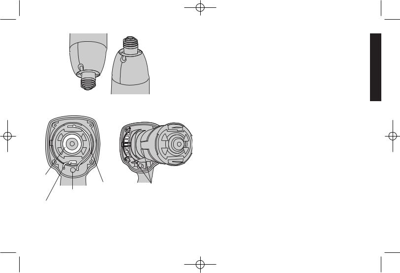
QUICK RELEASE CHUCK
NOTE: The chuck accepts 1/4" hex accessories only.
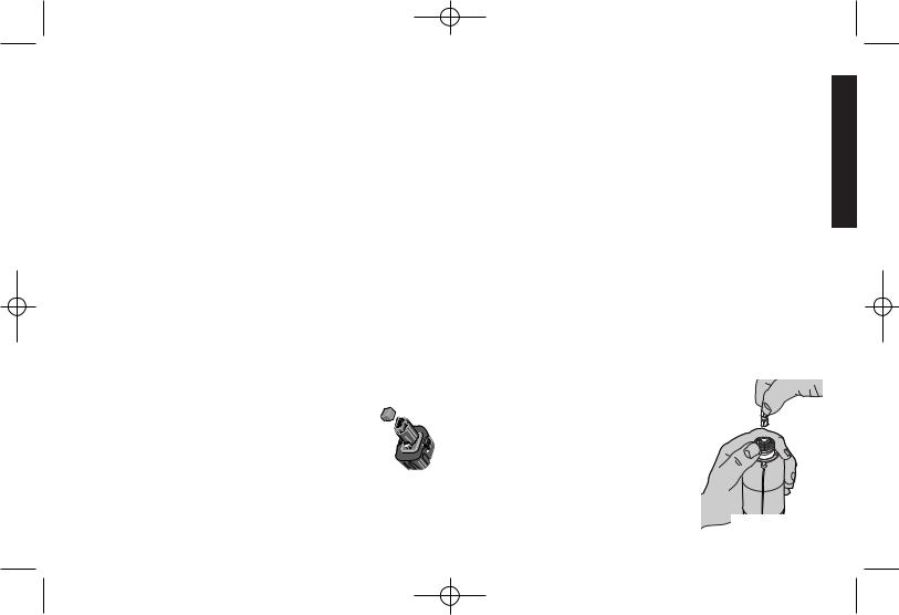
To install an accessory, pull the chuck collar toward the front of the tool, insert the accessory, and release the collar (Figure 1). The accessory will lock into place.
To remove an accessory, pull the chuck collar toward the front of the tool. Remove the accessory and release the collar.
FORWARD/REVERSE BAR
For forward operation, push the bar from right FIG. 1 to left. For reverse operation, push the bar
English

DW900,DW901/383609 bc 5/8/02 2:59 PM Page 4
English
from left to right. The center position of the bar locks-off the tool. Be sure to release the trigger when changing the position of the forward/reverse bar.
SWITCH
To turn the tool on, squeeze the trigger switch. When the tool reaches its set torque level, the spindle will stop and the LED light on the back of the tool will illuminate. Do not continually squeeze and release the trigger when driving a joint; let the tool stop automatically.
Adjusting Torque Level
 WARNING: Remove the battery before making any adjustments.
1)Insert a 1/4" hex key into the spindle and turn it for one rotation. You may hear a click, indicating the clutch is coupled.
2)Insert the wireform tool into the two holes on the front ring of the unit. Be sure to insert the wireform tool as shown in Figure 2. Slowly turn the ring until the 

 symbol shows through the window on the top front of the tool. At this point, the wireform tool will drop into two adjustment notches under the front ring. You will not be able to rotate the ring after the wireform tool drops into the notches.
3)Remove the wireform tool from the front of the unit, and re-insert it as shown in Figure 3. NOTE: Remove wireform tool before operating unit.
4)Insert a 1/4" hex key into the spindle. Holding the unit and wireform tool in one hand, turn the hex key with the other hand (Figure 4). Turn the key counterclockwise to decrease the torque, clockwise to increase the torque. The spindle will click at each torque setting. Each click signifies a torque change of approximately 0.08 N-m. NOTE: If the spindle stops clicking and you feel significant resistance, the tool is at its torque limit. Do not force the tool beyond this point.
5)Remove wireform tool. Check the torque of the tool with a torque
4
FIG. 2 |
FIG. 3 |
WINDOW
ADJUST
TOOL
DECREASE
TORQUE
OPTIONAL |
FIG. 5 |
|
|
BALE HANDLE |
|
INCREASE
TORQUE
FIG. 4
DW900,DW901/383609 bc 5/8/02 2:59 PM Page 5
FIG. 5A
SETTING FOR N-m
FIG. 6
O-RING
BLACK
LEADWIRE
SETTING FOR in-lbs
|
|
Nm |
30 |
lbs |
in |
|
|
|
|
Nm |
|
|
- |
|
. |
|
|
in |
|
8 |
|
|
|
|
- |
|
|
|
|
lbs |
|
|
|
|
2 |
|
|
|
|
FIG. 7
RED
LED LEADWIRE ALIGN GROOVES TO GUIDE MOTOR INTO
HOUSING
meter. If necessary, readjust the torque up or down, following the above instructions.
This tool can achieve a maximum torque of approximately. 4.5 N-m and a minimum torque of approximately 1.5 N-m.
Setting the Indicator Ring
Once the desired torque is confirmed with a torque meter, use the wireform tool to set the indicator ring. Place the wireform tool about 1/4" into the holes on the front ring and turn the front ring until the numbers on the ring match the torque setting indicated by the torque meter (Figure 5).Setting the indicator ring will also seal the adjustment holes and prevent dirt from getting into the tool.
NOTE: Adjusting the indicator ring does not change the torque setting of the tool.
Replacing the Motor Cartridge
 WARNING: Remove the battery before performing any service.
NOTE: To avoid damage to the electronic module, this operation must be performed while wearing a grounding strap attached to earth ground.
1)Remove the four fasteners on the back of the tool; remove the endcap.
2)Remove the rubber O-ring from the motor (Figure 6).
3)Using pliers, remove the motor leadwires, noting color coding and connection scheme (Figure 6).
4)Grasp the motor and pull it out from the rear of the unit. Discard the motor.
5)Install the O-ring on the replacement motor.
6)Align the replacement motor with the housing (Figure 7). The groove formed by the sheet metal ring over the motor should align with the ribs located on the interior of the left housing (as
5
English
 Loading...