


BDTS200 10 INCH (254MM) TABLE SAW
INSTRUCTION MANUAL
THANK YOU FOR CHOOSING BLACK & DECKER!
GO TO WWW.BLACKANDDECKER.COM/NEWOWNER
TO REGISTER YOUR NEW PRODUCT.
BEFORE RETURNING THIS PRODUCT FOR ANY REASON PLEASE CALL
1-800-544-6986
BEFORE YOU CALL, HAVE THE FOLLOWING INFORMATIONAVAILABLE, CATALOG No., TYPE No., AND DATE CODE . IN MOST CASES,A
BLACK & DECKER REPRESENTATIVE CAN RESOLVE THE PROBLEM OVER THE PHONE. IF YOU HAVEASUGGESTION OR COMMENT,
GIVE USACALL. YOUR FEEDBACK IS VITALTO BLACK & DECKER.
SAVE THIS MANUAL FOR FUTURE REFERENCE.
VEA EL ESPAÑOL EN LA CONTRAPORTADA.
POUR LE FRANÇAIS, VOIR LA COUVERTURE ARRIÈRE.
INSTRUCTIVO DE OPERACIÓN, CENTROS DE SERVICIO Y
PÓLIZA DE GARANTÍA. ADVERTENCIA: LÉASE ESTE
INSTRUCTIVO ANTES DE USAR EL PRODUCTO.

TABLE OF CONTENTS |
|
IMPORTANT SAFETY INSTRUCTIONS . . . . . . . . . . . . . . . . . . . . . . . . . . . . . . . . . . . . . . . . . . . . . . . . . . . |
. . . . . . . .2 |
SAFETY GUIDELINES . . . . . . . . . . . . . . . . . . . . . . . . . . . . . . . . . . . . . . . . . . . . . . . . . . . . . . . . . . . . . . . . |
. . . . . . . .3 |
GENERAL SAFETY RULES . . . . . . . . . . . . . . . . . . . . . . . . . . . . . . . . . . . . . . . . . . . . . . . . . . . . . . . . . . . . |
. . . . . . . .4 |
ADDITIONAL SPECIFIC SAFETY RULES . . . . . . . . . . . . . . . . . . . . . . . . . . . . . . . . . . . . . . . . . . . . . . . . . |
. . . . . . . .5 |
FUNCTIONAL DESCRIPTION . . . . . . . . . . . . . . . . . . . . . . . . . . . . . . . . . . . . . . . . . . . . . . . . . . . . . . . . . . |
. . . . . . . .7 |
CARTON CONTENTS . . . . . . . . . . . . . . . . . . . . . . . . . . . . . . . . . . . . . . . . . . . . . . . . . . . . . . . . . . . . . . . . . |
. . . . . . . .7 |
ASSEMBLY . . . . . . . . . . . . . . . . . . . . . . . . . . . . . . . . . . . . . . . . . . . . . . . . . . . . . . . . . . . . . . . . . . . . . . . . . |
. . . . . . . .9 |
OPERATION . . . . . . . . . . . . . . . . . . . . . . . . . . . . . . . . . . . . . . . . . . . . . . . . . . . . . . . . . . . . . . . . . . . . . . . . |
. . . . . . .15 |
TROUBLESHOOTING . . . . . . . . . . . . . . . . . . . . . . . . . . . . . . . . . . . . . . . . . . . . . . . . . . . . . . . . . . . . . . . . |
. . . . . . .25 |
MAINTENANCE . . . . . . . . . . . . . . . . . . . . . . . . . . . . . . . . . . . . . . . . . . . . . . . . . . . . . . . . . . . . . . . . . . . . . . |
. . . . . . .25 |
SERVICE . . . . . . . . . . . . . . . . . . . . . . . . . . . . . . . . . . . . . . . . . . . . . . . . . . . . . . . . . . . . . . . . . . . . . . . . . . . |
. . . . . . .26 |
ACCESSORIES . . . . . . . . . . . . . . . . . . . . . . . . . . . . . . . . . . . . . . . . . . . . . . . . . . . . . . . . . . . . . . . . . . . . . |
. . . . . . .26 |
WARRANTY . . . . . . . . . . . . . . . . . . . . . . . . . . . . . . . . . . . . . . . . . . . . . . . . . . . . . . . . . . . . . . . . . . . . . . . . . |
. . . . . . .26 |
SPANISH . . . . . . . . . . . . . . . . . . . . . . . . . . . . . . . . . . . . . . . . . . . . . . . . . . . . . . . . . . . . . . . . . . . . . . . . . . . |
. . . . . . .27 |
FRENCH . . . . . . . . . . . . . . . . . . . . . . . . . . . . . . . . . . . . . . . . . . . . . . . . . . . . . . . . . . . . . . . . . . . . . . . . . . . |
. . . . . . .43 |
SERVICE CENTER LOCATIONS . . . . . . . . . . . . . . . . . . . . . . . . . . . . . . . . . . . . . . . . . . . . . . . . . . . . . . . . |
back cover |
2

SAFETY GUIDELINES - DEFINITIONS
It is important for you to read and understand this manual. The information it contains relates to protecting YOUR SAFETY and PREVENTING PROBLEMS. The symbols below are used to help you recognize this information.
 DANGER: Indicates an imminently hazardous situation which, if not avoided, will result in death or serious injury.
 WARNING: Indicates a potentially hazardous situation which, if not avoided, could result in death or serious injury.
 CAUTION: Indicates a potentially hazardous situation which, if not avoided, may result in minor or moderate injury. CAUTION: Used without the safety alert symbol indicates potentially hazardous situation which, if not avoided, may result
in property damage.
CALIFORNIA PROPOSITION 65
 WARNING: Some dust created by power sanding, sawing, grinding, drilling, and other construction activities contains chemicals known to cause cancer, birth defects or other reproductive harm. Some
examples of these chemicals are:
•lead from lead-based paints,
•crystalline silica from bricks and cement and other masonry products, and
•arsenic and chromium from chemically-treated lumber (CCA).
Your risk from these exposures varies, depending on how often you do this type of work. To reduce your exposure to these chemicals: work in a well ventilated area, and work with approved safety equipment, such as those dust masks that are specially designed to filter out microscopic particles.
•Avoid prolonged contact with dust from power sanding, sawing, grinding, drilling, and other construction activities. Wear protective clothing and wash exposed areas with soap and water. Allowing dust to get into your mouth, eyes, or lay on the skin may promote absorption of harmful chemicals.
Use of this tool can generate and/or disperse dust, which may cause serious and permanent respiratory or other injury. Always use NIOSH/OSHA approved respiratory protection appropriate for the dust exposure. Direct particles away from face and body.
Wear appropriate hearing protection during use. Under some conditions and duration of use, noise from this product may contribute to hearing loss.
SAVE THESE INSTRUCTIONS!
3

GENERAL SAFETY RULES
 WARNING: READ ALL INSTRUCTIONS BEFORE OPERATING PRODUCT. FAILURE TO FOLLOW ALL INSTRUCTIONS LISTED BELOW MAY RESULT IN ELECTRIC SHOCK, FIRE AND OR SERIOUS INJURY.
IMPORTANT SAFETY INSTRUCTIONS
1.FOR YOUR OWN SAFETY, READ THE INSTRUCTION MANUAL BEFORE OPERATING THE MACHINE.
Learning the machine’s application, limitations, and specific hazards will greatly minimize the possibility of accidents and injury.
2.WEAR EYE AND HEARING PROTECTION. ALWAYS USE SAFETY GLASSES. Everyday eyeglasses are NOT safety glasses. USE CERTIFIED SAFETY EQUIPMENT. Eye protection equipment should comply with ANSI Z87.1 standards. Hearing equipment should comply with ANSI S3.19 standards.
3.WEAR PROPER APPAREL. Do not wear loose clothing, gloves, neckties, rings, bracelets, or other jewelry which may get caught in moving parts. Nonslip footwear is recommended. Wear protective hair covering to contain long hair.
4.DO NOT USE THE MACHINE IN A DANGEROUS ENVIRONMENT. The use of power tools in damp or wet locations or in rain can cause shock or electrocution. Keep your work area well-lit to prevent tripping or placing arms, hands, and fingers in danger.
5.MAINTAIN ALL TOOLS AND MACHINES IN PEAK CONDITION. Keep tools sharp and clean for best and safest performance. Follow instructions for lubricating and changing accessories. Poorly maintained tools and machines can further damage the tool or machine and/or cause injury.
6.CHECKFORDAMAGEDPARTS.Before using the machine, check for any damaged parts. Check for alignment of moving parts, binding of moving parts, breakage of parts, and any other conditions that may affect its operation. A guard or any other part that is damaged should be properly repaired or replaced.
Damaged parts can cause further damage to the machine and/or injury.
7.KEEP THE WORK AREACLEAN. Cluttered areas and benches invite accidents.
8.KEEP CHILDREN AND VISITORS AWAY. Your shop is a potentially dangerous environment. Children and visitors can be injured.
9.REDUCE THE RISK OF UNINTENTIONAL STARTING.
Make sure that the switch is in the “OFF” position before plugging in the power cord. In the event of a power failure, move the switch to the “OFF” position. An accidental start-up can cause injury.
10.USE THE GUARDS. Check to see that all guards are in place, secured, and working correctly to reduce the risk of injury.
11.REMOVE ADJUSTING KEYS AND WRENCHES BEFORE STARTING THE MACHINE. Tools, scrap pieces, and other debris can be thrown at high speed, causing injury.
12.USE THE RIGHT MACHINE. Don’t force a machine or an attachment to do a job for which it was not designed. Damage to the machine and/or injury may result.
13.USE RECOMMENDED ACCESSORIES. The use of accessories and attachments not recommended may cause damage to the machine or injury to the user.
14.USE THE PROPER EXTENSION CORD. Make sure your extension cord is in good condition. When using an extension cord, be sure to use one heavy enough to carry the current your product will draw. An
undersized cord will cause a drop in line voltage, resulting in loss of power and overheating. See the Extension Cord Chart for the correct size depending on the cord length and nameplate ampere rating. If in doubt, use the next heavier gauge. The smaller the gauge number, the heavier the cord.
15.SECURE THE WORKPIECE. Use clamps or a vise to hold the workpiece when practical. Loss of control of a workpiece can cause injury.
16.FEED THE WORKPIECE AGAINST THE DIRECTION OF THE ROTATION OF THE BLADE, CUTTER, OR ABRASIVE SURFACE. Feeding it from the other direction will cause the workpiece to be thrown out at high speed.
17.DON’T FORCE THE WORKPIECE ON THE MACHINE.
Damage to the machine and/or injury may result.
18.DON’T OVERREACH. Loss of balance can make you fall into a working machine, causing injury.
19.NEVER STAND ON THE MACHINE. Injury could occur if the tool tips, or if you accidentally contact the cutting tool.
20.NEVER LEAVE THE MACHINE RUNNING UNATTENDED. TURN THE POWER OFF. Don’t leave the machine until it comes to a complete stop. Achild or visitor could be injured.
21.TURN THE MACHINE “OFF”, AND DISCONNECT THE MACHINE FROM THE POWER SOURCE before installing or removing accessories, before adjusting or changing set-ups, or when making repairs. An accidental start-up can cause injury.
22.MAKE YOUR WORKSHOP CHILDPROOF WITH PADLOCKS, MASTER SWITCHES, OR BY REMOVING STARTER KEYS. The accidental start-up of a machine by a child or visitor could cause injury.
23. STAY ALERT, WATCH WHAT YOU ARE DOING, AND
USE COMMON SENSE. DO NOT USE THE MACHINE WHEN YOU ARE TIRED OR UNDER THE INFLUENCE OF DRUGS, ALCOHOL, OR MEDICATION. A moment of inattention while operating power tools may result in injury.
24.  WARNING: USE OF THIS TOOL CAN
GENERATE AND DISBURSE DUST OR OTHER AIRBORNE PARTICLES, INCLUDING WOOD DUST, CRYSTALLINE SILICA DUST AND ASBESTOS DUST. Direct particles away from face and body. Always operate tool in well ventilated area and provide for proper dust removal. Use dust collection system wherever possible. Exposure to the dust may cause serious and permanent respiratory or other injury, including silicosis (a serious lung disease), cancer, and death. Avoid breathing the dust, and avoid prolonged contact with dust. Allowing dust to get into your mouth or eyes, or lay on your skin may promote absorption of harmful material. Always use properly fitting NIOSH/OSHA approved respiratory protection appropriate for the dust exposure, and wash exposed areas with soap and water.
4
ADDITIONAL SPECIFIC SAFETY RULES
 WARNING: READ ALL INSTRUCTIONS BEFORE OPERATING PRODUCT. FAILURE TO FOLLOW ALL INSTRUCTIONS LISTED BELOW MAY RESULT IN ELECTRIC SHOCK, FIRE AND OR SERIOUS INJURY.
1. DO NOT OPERATE THIS MACHINE until it is assembled and installed according to the instructions.
2.OBTAIN ADVICE FROM YOUR SUPERVISOR, instructor, or another qualified person if you are not familiar with the operation of this machine.
3.FOLLOW ALL WIRING CODES and recommended electrical connections.
4.USE THE GUARDS WHENEVER POSSIBLE. Check to see that they are in place, secured, and working correctly.
5.KICKBACK IS THE NATURAL TENDENCY OF THE WORKPIECE TO BE THROWN BACK AT THE OPERATOR when the workpiece initially contacts the blade or if the workpiece pinches the blade. Kickback is dangerous and can result in serious injury.
AVOID KICKBACK by:
A.keeping blade sharp and free of rust and pitch.
B.keeping rip fence parallel to the saw blade.
C.using saw blade guard and spreader for every possible operation, including all through sawing.
D.pushing the workpiece past the saw blade prior to release.
E.never ripping a workpiece that is twisted or warped, or does not have a straight edge to guide along the fence.
F.using featherboards when the anti-kickback device cannot be used.
G.never sawing a large workpiece that cannot be controlled.
H.never using the fence as a guide when crosscutting.
I.never sawing a workpiece with loose knots or other flaws.
6.ALWAYS USE GUARDS, SPLITTER, AND ANTI-KICKBACK FINGERS whenever possible.
7.REMOVE CUT-OFF PIECES AND SCRAPS from the table before starting the saw. The vibration of the machine may cause them to move into the saw blade and be thrown out. After cutting, turn the machine off. After the blade has come to a complete stop, remove all debris.
8.NEVER START THE MACHINE with the workpiece against the blade.
9.NEVER run the workpiece between the fence and a moulding cutterhead.
10.CUTTING THE WORKPIECE WITHOUT THE USE OF A FENCE OR MITER GAUGE IS KNOWN AS “FREEHAND” CUTTING. NEVER perform “free-hand”
operations. Use either the fence or miter gauge to position and guide the workpiece.
11.HOLD THE WORKPIECE FIRMLY against the miter gauge or fence.
12.CUTTING COMPLETELY THROUGH THE WORKPIECE IS KNOWN AS “THROUGH-SAWING”.
Ripping and cross-cutting are through-sawing operations. Cutting with the grain (or down the length of the workpiece) is ripping. Cutting across the grain (or across the workpiece) is cross-cutting. Use a fence or fence system for ripping. DO NOT use a fence or fence system for cross-cutting. Instead, use a miter gauge. USE PUSH STICK(S) for ripping a narrow workpiece.
13.AVOID AWKWARD OPERATIONS AND HAND POSITIONS where a sudden slip could cause a hand to move into the blade.
14.KEEP ARMS, HANDS, AND FINGERS away from the blade.
15.NEVER have any part of your body in line with the path of the saw blade.
16.NEVER REACH AROUND or over the saw blade.
17.NEVER attempt to free a stalled saw blade without first turning the machine “OFF”.
18.PROPERLY SUPPORT LONG OR WIDE workpieces.
19.NEVER PERFORM LAYOUT, assembly or set-up work on the table/work area when the machine is running.
20.TURN THE MACHINE “OFF” AND DISCONNECT THE MACHINE from the power source before installing or removing accessories, before adjusting or changing set-ups, or when making repairs.
21.TURN THE MACHINE “OFF”, disconnect the machine from the power source, and clean the table/work area before leaving the machine. LOCK THE SWITCH IN THE “OFF” POSITION to prevent unauthorized use.
22.ADDITIONAL INFORMATION regarding the safe and proper operation of power tools (i.e. a safety video) is available from the Power Tool Institute, 1300 Sumner Avenue, Cleveland, OH 44115-2851 (www.powertoolinstitute.com). Information is also available from the National Safety Council, 1121
Spring Lake Drive, Itasca, IL 60143-3201. Please refer to the American National Standards Institute ANSI 01.1 Safety Requirements for Woodworking Machines and the U.S. Department of Labor OSHA 1910.213 Regulations.
SAVE THESE INSTRUCTIONS. Refer to them often
and use them to instruct others.
5

POWER CONNECTIONS
A separate electrical circuit should be used for your machines. This circuit should not be less than #12 wire and should be protected with a 20 Amp time lag fuse. If an extension cord is used, use only 3-wire extension cords which have 3-prong grounding type plugs and matching receptacle which will accept the machine’s plug. Before connecting the machine to the power line, make sure the switch (s) is in the “OFF” position and be sure that the electric current is of the same characteristics as indicated on the machine. All line connections should make good contact. Running on
low voltage will damage the machine.
 WARNING: SHOCK HAZARD. DO NOT EXPOSE THE MACHINE TO RAIN OR OPERATE THE MACHINE IN DAMP LOCATIONS.
GROUNDING INSTRUCTIONS
 WARNING: SHOCK HAZARD. THIS MACHINE MUST BE GROUNDED WHILE IN USE TO PROTECT THE OPERATOR FROM ELECTRIC SHOCK.
Your machine is wired for 120 Volt, 60 HZ alternating current. Before connecting the machine to the power source, make sure the switch is in the “OFF” position.
1. All grounded, cord-connected machines:
In the event of a malfunction or breakdown, grounding provides a path of least resistance for electric current to reduce the risk of electric shock. This machine is equipped with an electric cord having an equipmentgrounding conductor and a grounding plug. The plug must be plugged into a matching outlet that is properly installed and grounded in accordance with all local codes and ordinances.
Do not modify the plug provided - if it will not fit the outlet, have the proper outlet installed by a qualified electrician.
Improper connection of the equipment-grounding conductor can result in risk of electric shock. The conductor with insulation having an outer surface that is green with or without yellow stripes is the equipmentgrounding conductor. If repair or replacement of the electric cord or plug is necessary, do not connect the equipment-grounding conductor to a live terminal.
Check with a qualified electrician or service personnel if the grounding instructions are not completely understood, or if in doubt as to whether the machine is properly grounded.
Use only 3-wire extension cords that have 3-prong grounding type plugs and matching 3-conductor receptacles that accept the machine’s plug, as shown in Fig. A.
Repair or replace damaged or worn cord immediately.
GROUNDED OUTLET BOX
CURRENT
CARRYING
PRONGS
2. Grounded, cord-connected machines intended for use on a supply circuit having a nominal rating less than 150 volts:
If the machine is intended for use on a circuit that has an outlet that looks like the one illustrated in Fig. A, the machine will have a grounding plug that looks like the plug illustrated in Fig. A. A temporary adapter, which looks like the adapter illustrated in Fig. B, may be used to connect this plug to a matching 2-conductor receptacle as shown in Fig. B if a properly grounded outlet is not available. The temporary adapter should be used only until a properly grounded outlet can be installed by a qualified electrician. The green-colored rigid ear, lug, and the like, extending from the adapter must be connected to a permanent ground such as a properly grounded outlet box. Whenever the adapter is used, it must be held in place with a metal screw.
NOTE: In Canada, the use of a temporary adapter is not permitted by the Canadian Electric Code.
 WARNING: SHOCK HAZARD. IN ALL CASES, MAKE CERTAIN THE RECEPTACLE IN QUESTION IS PROPERLY GROUNDED. IF YOU ARE NOT SURE HAVE A QUALIFIED ELECTRICIAN CHECK THE RECEPTACLE.
GROUNDED OUTLET BOX
GROUNDING
MEANS
ADAPTER
GROUNDING BLADE
IS LONGEST OF THE 3 BLADES
Fig. A |
6 |
Fig. B |

EXTENSION CORDS
 WARNING: Use proper extension cords. Make sure your extension cord is in good condition and is a 3-wire extension cord which has a 3-prong grounding type plug and matching receptacle which will accept the machine’s plug. When using an extension cord, be sure to use one heavy enough to carry the current of the machine. An undersized cord will cause a drop in line voltage, resulting in loss of power and overheating. Fig. C shows the correct gauge to use depending on the cord length. If in doubt, use the next heavier gauge. The smaller the gauge number, the heavier the cord.
FUNCTIONAL DESCRIPTION
FOREWORD
MINIMUM GAUGE EXTENSION CORD
RECOMMENDED SIZES FOR USE WITH STATIONARY ELECTRIC MACHINES
Ampere |
|
Total Length |
Gauge of |
Rating |
Volts |
of Cord in Feet |
Extension Cord |
0-6 |
120 |
up to 25 |
18 AWG |
0-6 |
120 |
25-50 |
16 AWG |
0-6 |
120 |
50-100 |
16 AWG |
0-6 |
120 |
100-150 |
14 AWG |
6-10 |
120 |
up to 25 |
18 AWG |
6-10 |
120 |
25-50 |
16 AWG |
6-10 |
120 |
50-100 |
14 AWG |
6-10 |
120 |
100-150 |
12 AWG |
10-12 |
120 |
up to 25 |
16 AWG |
10-12 |
120 |
25-50 |
16 AWG |
10-12 |
120 |
50-100 |
14 AWG |
10-12 |
120 |
100-150 |
12 AWG |
|
|
|
|
12-16 |
120 |
up to 25 |
14 AWG |
12-16 |
120 |
25-50 |
12 AWG |
12-16 |
120 |
GREATER THAN 50 FEET NOT RECOMMENDED |
|
|
|
|
|
Fig. C
Model BDTS200 is a 10 inch Table Saw designed to give high quality performance with depth of cut capacity up to 3 inches (76mm) at 90° and 2 inches (51mm) at 45° for clean cutting of standard stock sizes.
NOTICE: THE PHOTO ON THE MANUAL COVER ILLUSTRATES THE CURRENT PRODUCTION MODEL. ALL OTHER ILLUSTRATIONS CONTAINED IN THE MANUAL ARE REPRESENTATIVE ONLY AND MAY NOT DEPICT THE ACTUAL COLOR, LABELING OR ACCESSORIES AND ARE INTENDED TO ILLUSTRATE TECHNIQUE ONLY.
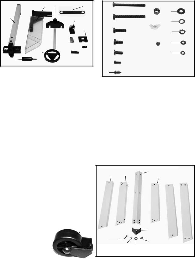
CARTON CONTENTS
MOTORIZED BENCH SAW PARTS
Fig. 1 illustrates the saw removed from the container. Figs. 2 and Fig. 3 illustrate the loose items packed with the saw. Fig. 4 illustrates the loose items packed for the stand.
Fig. 1
7
2 |
5 |
11 |
||||
1 |
|
6 |
|
|
||
|
|
|
|
|||
|
|
9 |
|
|||
4 |
|
7 |
|
|
|
|
|
|
|
|
|
||
|
|
|
|
|
|
|
|
|
|
|
|
|
|
|
|
|
|
10 |
||
|
|
|
|
|||
|
|
|
||||
|
|
|
|
|
||
3 |
|
8 |
|
|||
Fig. 2
Fig. 2 Parts
1.Rip Fence
2.Splitter and Guard Assembly
3.Lock Handle for Rip Fence
4.Blade Raising and Lowering Handwheel
5.Miter Gage
6.Splitter Support Bracket
7.Splitter Bracket
8.Handle for Blade Raising and Lowering Handwheel
9.Miter Gage Holder
10.Spring Clip for Miter Gage Holder
11.Blade Wrench
Fig. 4 Stand Hardware
1.Leg (4) (2 with holes at base for attaching wheel bracket and brace)
2.3/8 inchFlat Washer for Mounting Saw to Stand & for Assembling Stand (24)
3.Foot (4)
4.M8x1.25 Hex Nut for Mounting Saw to Stand & for Assembling Stand (20)
5.M8x1.25x45mm Hex Screw for Mounting Saw to Stand (4)
6.M8x1.25x20mm Carriage Head Bolts for Assembling Stand (16)
7.18-1/2 inchTop Front and Rear Brackets (2)
8.17 inch Top Side Brackets (2)
9.22 inch Bottom Front and Rear Brackets (2)
10.20-3/8 inch Bottom Side Brackets (2)
11.Wheel Assembly (2)
12. 25 inch Brace (1) |
11 |
|
|
1 |
|
|
|
|
|
|
|
|
|
|
|
8 |
|
|
|
11 |
|||||||
2 |
|
|
|
||||||||
|
|
|
|||||||||
|
|
|
|
|
|
|
|
|
12 |
||
|
|
|
|
|
|
|
|
|
|||
|
|
|
|
|
|
|
|
|
|
||
3 |
9 |
|
|
|
13 |
||||||
|
|
|
|||||||||
|
|
|
|
|
|
|
|
|
|||
|
|
|
|
|
|
|
|
|
|||
|
|
|
|
|
|
|
|
|
|
||
4 |
|
|
|
|
|
|
|
|
|
|
14 |
10 |
|
|
|||||||||
|
|
|
|||||||||
|
|
|
|
|
|||||||
5 |
|
|
|
|
|
|
|
|
|
15 |
|
|
|
|
|
|
|
|
|
|
|||
6 |
|
|
|
|
|
|
|
|
|
|
|
|
|
|
|
|
|
|
|
|
|
|
|
7
Fig. 3
Fig. 3 Hardware
1.M6x1x55mm Pan Head Screw (1)
2.1/4-20x2 inch Hex Head Screw (1)
3.M6x1x20mm Hex Head Screw (1)
4.1/4-20x1/2 inch Hex Head Screw (2)
5.M6x1x12mm Flat Head Screw (1)
6.M4x.7x10mm Pan Head Screw (1)
7.M4x.2x10mm Pan Head Screw (4)
8.M8x1.25 Hex Nut (1)
9.M6x1 Wing Nut (1)
10.M4.7 Hex Nut (1)
11.M6.4 Flat Washer (3)
12.1/4 inch Internal Tooth Lockwasher (1)
13.1/4 inch External Tooth Lockwasher (5)
14.3/16 inch Flat Washer (4)
15.3/16 inch External Tooth Flat Washer (1)
10 |
7 |
1 |
12 |
||
|
|
8 |
9 |
|
|
|
|
|
|
|
|
|
|
|
|
|
|
|
|
|
|
|
|
|
3 |
5 |
6 |
|
42
Fig. 4
8

ASSEMBLY
ASSEMBLY TOOLS REQUIRED |
* 13mm wrench for stand bolts |
|
* 10mm wrench for splitter assembly bolts |
||
(None supplied) |
||
* Straight edge and/or framing square for adjustments |
||
* Phillips head screw driver |
||
|
ASSEMBLY TIME ESTIMATE - 1 hour
ELEVATING AND SUPPORTING SURFACES FOR A SAW WITH NO STAND
 WARNING: THE SAW MUST BE PROPERLY SECURED TO A SUPPORTING SURFACE. ALSO, FAILURE TO PROVIDE A SAWDUST FALL-THROUGH AND REMOVAL HOLE WILL ALLOW SAWDUST TO BUILD UP AROUND THE MOTOR, CAUSING A POSSIBLE FIRE HAZARD AND/OR MOTOR DAMAGE.
 WARNING: DISCONNECT MACHINE FROM POWER SOURCE.
The saw must be elevated enough for sawdust to fall through the bottom of the saw and not build up around the motor.
Position the four mounting holes located on the base of the saw cabinet (two of which are shown at (A) Fig. 4A) over whatever proper support you are using. Then securely fasten the saw to the supports. The saw can be secured by fastening the stand through the mounting holes with suitable hardware (not supplied).
 WARNING: THE SAW SUPPORT MUST BE STABLE
AND ABLE TO SUPPORT 300 POUNDS.
You can also construct a simple elevated support, as shown in Fig. 4B.
WARNING: USE A GOOD GRADE OF PLYWOOD |
|
|
WITH A MINIMUM 3/4 INCH THICKNESS. DO NOT |
|
|
MAKE THE MOUNTING BOARD FROM PARTICLE |
A |
|
BOARD SINCE PARTICLE BOARD BREAKS EASILY. |
||
|
 WARNING: A HOLE MUST BE PROVIDED IN THIS SUPPORT TO ALLOW SAWDUST TO FALL THROUGH.
Square the saw on the supporting surface and mark the location for four 5/16 inch holes to be drilled (Fig. 4B).
 WARNING: MAKE SURE THERE IS AT LEAST 3 INCH ON ALL FOUR SIDES OF THE
BASE.
Set the saw aside and then drill holes in these marks. Locate and mark an 11 inch or 12 inch square centered between the four mounting holes. Cut out and remove the square (Fig. 4B). To elevate the supporting surface, measure two 2x4s (A) Fig. 4B to the width of two opposite sides of the supporting surface. Attach the supporting surface to the narrow edges of the 2X4s (as shown in Fig. 4B) using wood screws (not provided) in at least three spots (B) Fig. 4B on each side.
Fasten the saw to the surface by inserting suitable hardware (not supplied) through the mounting holes on the saw and into the previously drilled holes. While using the saw, periodically remove the sawdust buildup from below the saw.
Fig. 4A
SAW PLACEMENT |
|
5/16" PILOT |
B |
|
|
HOLES |
|||
MARKS |
|
|
|
|
|
|
3" |
MINIMUM |
|
|
|
|
|
|
|
|
|
CUTOUT |
MINIMUM |
|
|
|
MINIMUM |
|
|
|
|
|
|
|
3" |
MINIMUM |
|
|
|
|
|
||
B |
|
|
|
A |
|
|
|
|
|
Fig. 4B
9
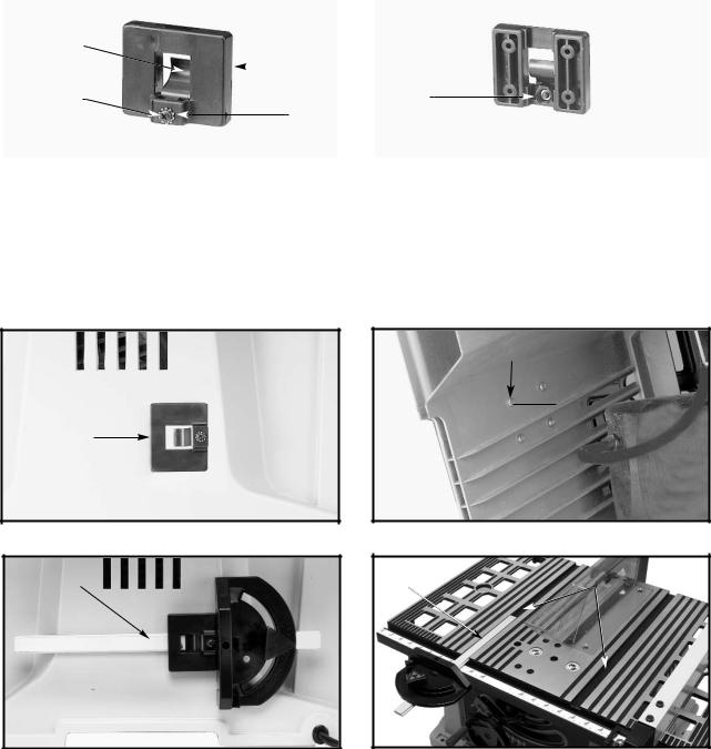
ATTACHING MITER GAUGE HOLDER
 WARNING: DISCONNECT MACHINE FROM POWER SOURCE.
E |
|
|
|
|
F |
|
A |
|
G |
|
|
|||
|
|
|
||
|
|
B |
|
|
|
|
|
|
|
Fig. 5 |
|
|
|
Fig. 6 |
1.Attach the spring clip (E) Fig. 5 to the miter gauge holder (A) using an M4x.7x10mm pan head screw (F), 3/16 inch external tooth lockwasher, (B) and M4x.7 hex nut.
NOTE: The hex nut (G) Fig. 6 will fit into the recess at the back of the miter gauge holder (A) Fig. 5 to keep the spring clip (E) secured to the miter gauge holder.
2.Attach the miter gauge holder (A) Fig. 7 to the left side of the saw cabinet using the four M4x.2x10mm screws (B) Fig. 8, and 3/16 inch flat washers (C) from inside of the saw cabinet.
3.Fig. 9 illustrates the miter gauge (D) inserted into the holder.
A
Fig. 7
D
Fig. 9
C
B
Fig. 8
B
A
Fig. 10
MITER GAUGE
The miter gauge is shipped assembled and is supplied with a T-slot bar (A) Fig. 10 that is inserted into either one of the two T-slotted miter gauge grooves (B) located in the table top. The T-slot prevents the miter gauge from falling when it is extended beyond the front of the table when cross-cutting extra wide workpieces.
10
ASSEMBLING STAND
1.Attach the rubber feet (H) Fig. 11 to the bottom of each leg (F).
Locate the two legs (F) which have holes at the bottom for attaching the wheel brackets (G) and brace (E). (Make sure wheels and brackets are properly oriented. See inset Figure 12). To attach the brackets, remove the nuts from the bolts and insert the bolts through the holes in the bottom of the two legs and into the holes in brace (E). Thread the nuts back on the bolts and tighten. Assemble the stand as shown in Fig. 11, using 16 M8x1.25x20mm carriage head bolts, 3/8 inch flat washers and M8x1.25 hex nuts. Align the holes in the stand legs (F) with the holes in the brackets. Insert the carriage head bolt through the hole in the leg and the hole in the bracket, place a flat washer on the carriage head bolt and thread a hex nut onto the carriage head bolt. Repeat this process for the 15 remaining holes in the legs and brackets.
NOTE: Loosely tighten the hardware for further adjustment.
Letters are on the stand brackets to ease assembly: A - Top front and rear brackets
B - Top side brackets
C - Bottom side brackets
D - Bottom front and rear brackets E - Bottom brace
NOTE: Each rubber foot is provided with holes for mounting the stand to the floor surface if required.
 B
B
A
F
C 
H
D
G
E
Fig. 11
Wheel
Fig. 12
SAW TO STAND
1.Turn saw table face down on a piece of cardboard to protect the table surface. Place stand upside down onto saw and align the four holes in the stand with the mounting holes in the saw.
2.Place a 3/8 inch flat washer on a M8x1.25x45mm hex head screw. Insert the hex head screw through the mounting hole in the saw and the mounting hole in the stand. Place another 3/8 inch flat washer on the hex head screw and thread a M8x1.25 hex nut on the screw and loosely tighten. Complete this process for the other three holes.
3.Stand the saw upright, as shown in Fig. 13 (Saw is shown fully assembled here).
4.Push down on top of the saw so that the legs of the stand adjust to the surface of the floor. Tighten all hardware securely.
Fig. 13
11
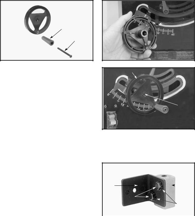
ATTACHING BLADE HEIGHT ADJUSTING HANDWHEEL
1.Insert an M6x1x55mm pan head screw (D) Fig. 14 through the handle (E). Attach the handle (E) to the handwheel
(A) by threading the screw (D) clockwise into the handwheel.
2.Attach the handwheel (A) Fig. 15 to the shaft (B). Align the flat on the inside of the handwheel to the flat on the shaft.
 A
A
 B
B
E
A

D
Fig. 14 |
Fig. 15 |
A
3.Fasten the handwheel (A) Fig. 16 to the shaft using an M6x1x12mm flat head screw (C)
C
Fig. 16
ATTACHING BLADE GUARD AND SPLITTER ASSEMBLY
 WARNING: DISCONNECT MACHINE FROM
POWER SOURCE.
 WARNING: PROPERLY ALIGN THE BLADE
GUARD AND SPLITTER ASSEMBLY WITH THE
SAW BLADE TO PREVENT KICKBACK.
1. |
Position the blade 90 degrees to the table and lock |
A |
|
|
B |
|
|
||||
|
in place. |
|
|
|
|
2. |
Fasten the splitter support bracket (A) Fig. 17 to the |
|
C |
||
|
|
|
|
||
|
splitter bracket (B) using two 1/4-20x1/2 inch hex |
|
|
D |
|
|
head screws (C) and two 1/4 inch external tooth |
|
|
|
|
|
lockwashers (D). |
|
|
|
|
|
|
|
Fig. 17 |
||
NOTE: Loosely tighten the screws for further adjustment.
12

3.Locate the 1/4-20x2 inch hex head screw (G) Fig. 18. Place the 1/4 inch internal tooth lockwasher (O) M6.4 flat washer (P) and the 1/4 inch external tooth lockwasher (R) on the screw (G).
4.Position the recessed end (E) Fig. 19 of the splitter bracket (B) against the end of the pivot rod (F), and fasten using the assembly in STEP 3. NOTE: Do not completely tighten screw (G) at this time. Assembly shown in Fig. 20.
NOTE: Loosely tighten the hardware for further adjustment.
5.Position the splitter (H) Fig. 21 against the splitter support bracket, making certain the two protrusions (K) on the splitter support bracket are inside the slot of splitter (H).
R
P
O
G
Fig. 18
G
Fig. 20
6.Attach the splitter (H) Fig. 22 to the splitter support bracket (B). Place a 1/4 inch external tooth lockwasher and an M6.4 flat washer on an M6x1x20mm hex head screw (L).
7.Insert the screw (L) Fig. 22 through the splitter support bracket (C) and the splitter (H). Place an M6.4 flat washer and a 1/4 inch external tooth lock washer on the screw (L). Thread an M6x1 wing nut
(M) Fig. 23 on the screw (L) Fig. 23.
F
E
B
Fig. 19
 H
H
 K
K
Fig. 21
C
 L
L
H
B
Fig. 22
13

NOTE: Before tightening the wing nut (M) Fig. 23, make certain a gap of at least 1/8 inch is between the bottom edge of the splitter (N) and the top surface of the table (P) and that the protrusions (K) are inside the slot of the splitter assembly (H).
8.Use a straight edge to see if the splitter (H) Fig. 24 is aligned with the saw blade (R). If an adjustment is necessary, the splitter (H) can be moved left or right and rotated.
9.When the splitter is properly aligned with the saw blade, tighten the screws (C) and (G) Fig. 25.
R
H
Fig. 24
ASSEMBLING RIP FENCE
1.Thread the M8x1.25 hex nut (A) Fig. 26, approximately halfway on the stud of the handle (B).
2.Thread the handle (B) Fig. 26 into the tapped hole
(C)in the fence cam (D). Tighten the hex nut (A) Fig. 27 against the cam (D).
3.The rip fence is usually set up on the right hand side of the saw table. Lift the lock handle (B) Fig. 28 and position the fence on the table. Push down on the handle (B) Fig. 28 to lock the fence in place.
D
A
Fig. 27
P
 H
H
N M
 K
K
Fig. 23
G 

C
Fig. 25
BD
C 
A
Fig. 26
B
Fig. 28
14
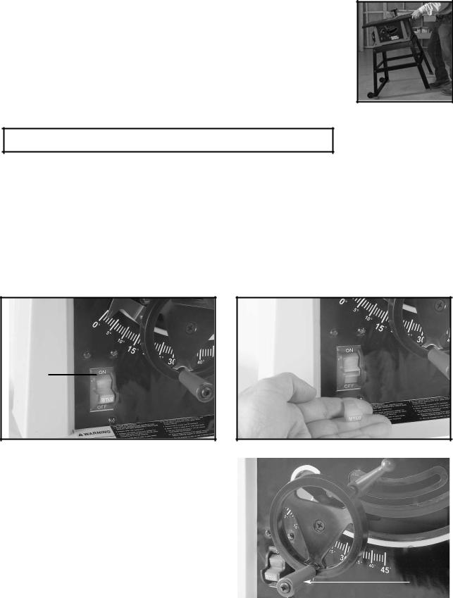
MOVING THE SAW
To move the saw, grasp the side of the table opposite of the wheels. Lift the saw so that it is slightly off the floor and pull the table to the desired location as shown.
 CAUTION: Not all floors are perfectly smooth, check both wheels each time you move the saw to ensure that they are not engaging the floor when the saw is at rest. Make sure all bolts are securely fastened.
OPERATION
OPERATIONAL CONTROLS AND ADJUSTMENTS
STARTING AND STOPPING SAW
The on/off switch (A) Fig. 29 is located on the front of the saw cabinet. To turn the saw “ON”, move the switch (A) up
to the “ON” position. To turn the saw “OFF”, move the switch (A) down to the “OFF” position.
 WARNING: Make sure that the switch is in the “OFF” position before plugging in the power cord. In the event of a power failure, move the switch to the “OFF” position. An accidental start-up can cause injury.
LOCKING SWITCH IN THE “OFF” POSITION
IMPORTANT: When the tool is not in use, the switch should be locked in the “OFF” position to prevent unauthorized use. To lock the tool, grasp the switch toggle (B) and pull it out of the switch (Fig. 30). With the switch toggle (B) removed, the switch will not operate. However, should the switch toggle be removed while the saw is running, the machine can be turned “OFF,” but cannot be restarted without re-inserting the switch toggle (B).
A
B 
Fig. 29 |
Fig. 30 |
BLADE HEIGHT ADJUSTMENT |
|
|
To adjust the height of the saw blade, turn the |
A |
|
handwheel (A) Fig. 31. Turning the handwheel |
||
|
||
clockwise lowers the blade and turning the handwheel |
|
|
Fig. 31 |
||
counter-clockwise raises the blade. |
15
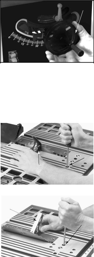
BLADE TILT ADJUSTMENT
To tilt the saw blade, loosen the lock handle (A)
Fig. 32 and move the handwheel (B) until the blade is at the desired angle. Tighten the lock handle (A).
NOTE: The lock handle (A) is spring-loaded. Pull out on the handle (A) and reposition it on the serrated stud located underneath the handle.
 WARNING: THE BLADE TILTING LOCK HANDLE
(A) MUST BE LOCKED DURING ALL CUTTING OPERATIONS.
B
A 
Fig. 32
90 AND 45 DEGREE POSITIVE STOP ADJUSTMENTS
Your saw is equipped with positive stops for rapid and accurate positioning of the saw blade at 90 and 45 degrees to
the table.
 WARNING: DISCONNECT MACHINE FROM POWER SOURCE.
TO ADJUST POSITIVE STOP AT 90 DEGREES |
|
|
1. Raise the saw blade to its maximum height. |
|
|
2. Loosen the blade tilting lock handle (A) Fig. 32, |
|
|
move the blade tilting mechanism (B) as far as |
|
|
possible to the left, and tighten the blade tilting lock |
|
|
handle (A). |
|
|
3. Place a square (A) Fig. 33 on the table with one end |
B |
|
|
||
of the square against the blade, and check to see if |
A |
|
the blade is 90 degrees to the table. If not, loosen |
||
the screw (B) Fig. 33 a few turns and move the |
|
|
blade tilting mechanism until the blade is 90 |
|
|
degrees to the table. Tighten the blade tilting lock |
|
|
handle (A) Fig. 32, and tighten the screw (B) Fig. 33 |
|
|
Fig. 33 |
||
until it stops. |
||
|
||
TO ADJUST POSITIVE STOP AT 45 DEGREES |
|
|
|
||
1. Raise the saw blade to its maximum height. |
A |
|
2. Loosen the blade tilting lock handle (A) Fig. 32, |
||
|
||
move the blade tilting mechanism (B) as far as |
|
|
possible to the right, and tighten the blade tilting |
|
|
lock handle (A). |
C |
|
3. Place a square (A) Fig. 34 on the table with one |
|
|
end of the square against the blade, and see if the |
|
|
blade is 45 degrees to the table. If not, loosen the |
|
|
screw (C) Fig. 34 a few turns and move the blade |
|
|
tilting mechanism (B) Fig. 32, until the blade is 45 |
|
|
degrees to the table. Tighten the blade tilting lock |
|
|
handle (A) Fig. 32, and tighten the screw (C) Fig. 34 |
|
|
Fig. 34 |
||
until it stops. |
||
|
16
RIP FENCE OPERATION
AND ADJUSTMENTS
1.To move the rip fence (A) Fig. 35 along the table, lift up the fence locking lever (B), slide the fence to the desired location on the table, and push down the fence locking lever (B).
2.The pointer indicates the distance from the fence to the saw blade. If an adjustment is required, loosen the screw (C) Fig. 35 and adjust.
IMPORTANT: The rip fence must be properly aligned to the miter gauge slot to prevent kickback when ripping.
3.The saw blade is set parallel to the miter gauge slot at the factory. The fence must be parallel to the miter gauge slot to do accurate work and to prevent kickback when ripping. To check the alignment:
4.Position the fence next to the miter gauge slot (Fig. 35). Clamp the fence to the table by pushing the locking lever (B) down . The edge of the fence should be parallel to the miter gauge slot.
5.If an adjustment is necessary, loosen the two screws (D) Fig. 35, and lift the locking lever (B). While holding the fence bracket (F) firmly toward the front of the saw, move the rear of the fence (A) until it is parallel with the miter gage slot. Tighten two screws (D) and push locking lever down (B).
6.Adjust the clamping action of the fence (A) Fig. 35 by lifting the locking lever (B) and turning the screw
(E) clockwise to increase, or counterclockwise to decrease the clamping action of the fence.
TABLE INSERT ADJUSTMENT
 WARNING: DISCONNECT MACHINE FROM POWER SOURCE.
1.Make sure that the table insert (A) Fig. 36, is flush with, or slightly below, the surface of the table (B).
2.If the table insert is above the surface of the table, tighten the two table insert screws (C) Fig. 36 to lower the insert.
D
E A
A
C
F
B
Fig. 35
A
C
B 
Fig. 36
17
MITER GAUGE OPERATION
AND ADJUSTMENTS
For cross-cutting (blade set 90 degrees to the table), the miter gauge can be used in either table slot. For bevel cross-cutting (with the blade tilted), use the miter gauge in the right table slot only so that the blade will be tilted away from the miter gauge and your hands.
To operate the miter gauge, loosen the lock knob (E) Fig. 37, and rotate the miter gauge to the desired angle.
E
Fig. 37
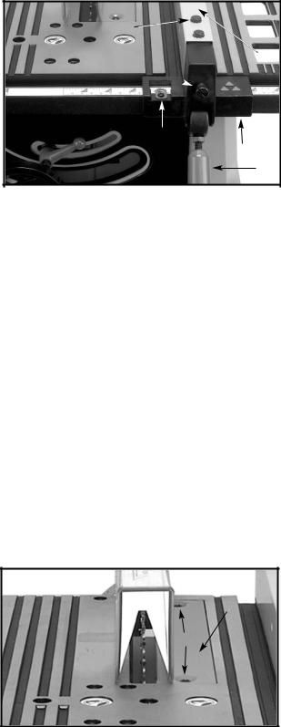
ADJUSTING BLADE PARALLEL TO MITER GAUGE SLOTS
The blade was adjusted parallel to the miter gauge slots at the factory. In order to ensure accurate cuts and help prevent kickback, check this adjustment.
To adjust:
 WARNING: DISCONNECT MACHINE FROM POWER SOURCE.
1.Raise the blade to its highest position and adjust the blade so that it is 90 degrees to the table.
2.Select a tooth on the saw blade that is set to the left. Mark this tooth with a pencil or marker.
3.Use a combination square (A) Fig. 38 against the miter gauge slot and adjust the blade (B) of the square until it touches the marked tooth.
4.Rotate the blade and check the same marked blade tooth at the rear of the saw table (Fig. 39).
B
A
Fig. 38 |
Fig. 39 |
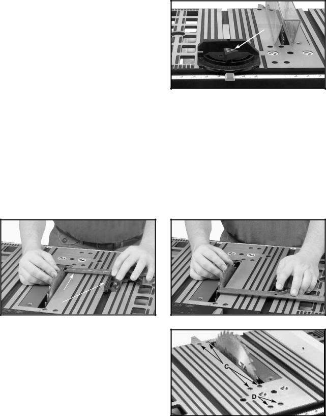
5.If the front and back measurements (Figs. 38 and 39) are not identical, you can adjust the blade. Start by loosening the nuts below the four screws (C) Fig. 40 on the table. Then loosen the screws (C). Carefully move the saw blade until the blade is parallel to the miter gauge slot. When done, tighten four nuts under the table and the four screws (C) Fig. 40 securely.
NOTE: If sufficient adjustment cannot be achieved by loosening the screws (C) Fig. 40, loosen the screw (D)
Fig. 40 necessary to make the adjustment.
Fig. 40
18
 Loading...