


 Loading...
B&K Components, Ltd.
User Manual
CT600.1
CT600.3
CT300.3
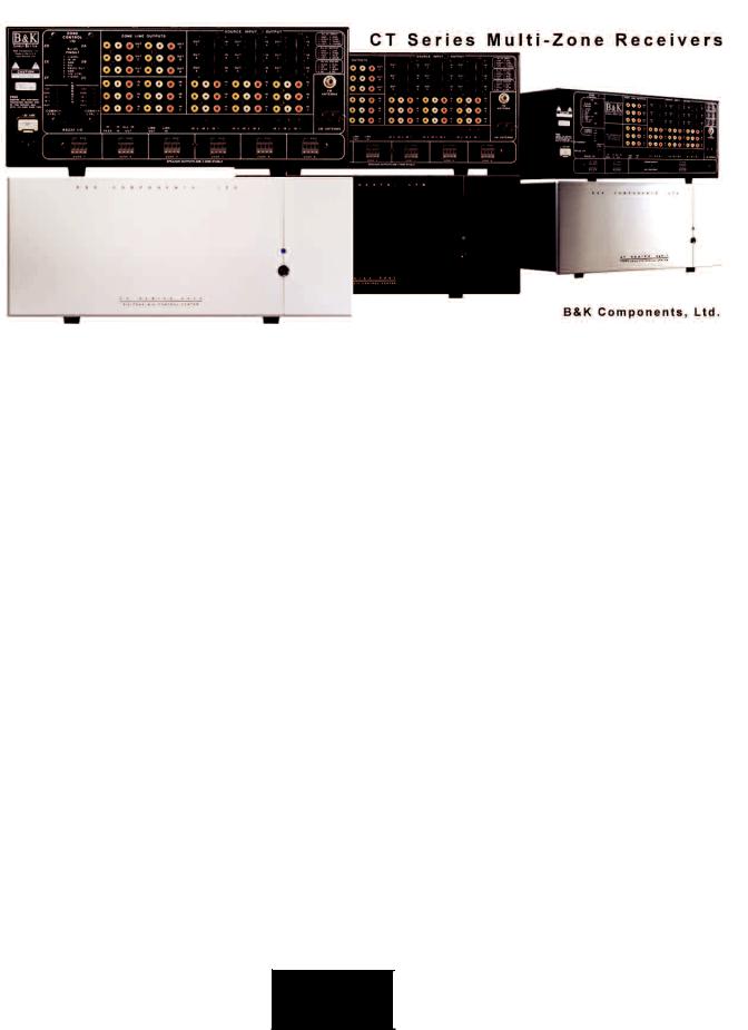
Multi-Zone Audio/Video Receivers
14067 121206

CT Receiver and Benefits
COMPLETE USER MANUAL - CT RECEIVER
© 2006 B & K Components, Ltd. All rights reserved.
The information in this manual is copyright protected. No part of this manual may be copied or reproduced in any form without prior written consent from B & K Components, Ltd.
B & K Components, Ltd. SHALL NOT BE LIABLE FOR OPERATIONAL, TECHNICAL OR EDITORIAL ERRORS/OMISSIONS MADE IN THIS MANUAL. The information in this manual may be subject to change without prior notice.
The information in this manual may be subject to change without prior notice.
***- PC requirements - 128MB RAM, Pentium grade or better processor, ‘. (Exception - BK Suite not supported on Windows NT) ***
SIMPLY BETTER!Ô © is a trademark of B & K Components, Ltd. All other brand or product names are trademarks or registered trademarks of their respective companies or organizations.
B & K Components, Ltd. sells its products through authorized dealers. Buying from an authorized B & K Components, Ltd. dealer insures that you have a FACTORY WARRANTY on your B & K Components, Ltd. product. A warranty on B & K Components, Ltd. products is NOT VALID if the products have been purchased from an unauthorized dealer or an E-tailer or if the factory serial number has been removed, defaced or replaced in any way.
Accessories Included
1 - MZ-128 Remote Control
4 - AAA Batteries
1 - Power Cord
1 - CT Series CD
1 - CT Receiver Quick Reference Manual
1 - FM Dipole Antenna
1 - AM Antenna
1 - DB9 to RJ-45 Adapter
1 - Warranty Card
B&K Components, Ltd.
2100 Old Union Road
Buffalo, New York 14227
1.800.543.5252 In NY: 716.656.0026
Fax: 716.656.1291 E-mail: info@bkcomp.com On the web: www.bkcomp.com
B&K
SIMPLY BETTER!

|
|
III |
Table of Contents |
|
|
Table of Contents |
III |
|
Introduction / Overview |
1 |
|
CT Receiver Features and Benefits |
2 |
|
CK 1.1 and CK1.2 Keypad Features and Benefits |
3 |
|
CT Receiver Front Panel |
4 |
|
CT Receiver Back Panel |
5 |
|
Accessories Guide |
6 |
|
The CK1.2 Keypad Front Panel/Back Panel |
6 |
|
The CK1.1 Keypad Front Panel/Back Panel |
7 |
|
B&K CT Series MZ-128 Remote Controller Reference Sheet |
8 |
|
DB-9 to RJ-45 Adapter P/N:13290 |
9 |
|
BK Toolbox CD-ROM P/N: 13323 |
9 |
|
Installation and System Diagrams |
10 |
|
Basic System Hookup |
11 |
|
Installation Considerations |
12 |
|
AC Power and Line Fuse |
13 |
|
Speaker Connections for CT Receiver |
13 |
|
Shared Source Inputs |
14 |
|
Dedicated (Local) Source Inputs |
14 |
|
Digital Audio Connection |
15 |
|
Buffered Outputs |
15 |
|
CT Receiver Speaker Connections |
16 |
|
Connecting an External Amplifier |
17 |
|
Composite Video Outputs |
18 |
|
CK1.2 Keypad Connections |
19 |
|
Adding Additional Keypads in the Same Zone |
20 |
|
IR Emitter Outputs |
21 |
|
Local IR Source Control |
21 |
|
Common Control Triggers |
22 |
|
Additional Connections |
23 |
|
Factory Reset |
23 |
|
System Expansion |
24 |
|
Connecting Multiple CT Receivers |
25 |
|
B&K
SIMPLY BETTER!

IV |
Table of Contents |
|
Adding a Home Theater |
26 |
Adding an HD6 |
27 |
Setup Using a PC and BK Suite |
28 |
Connecting to a PC |
29 |
BK Suite Setup and Overview |
30 |
BK Suite Task Bar Explained |
32 |
Basic Setup Menu |
33 |
Advanced Setup Menu |
35 |
Hardware Zone Settings - Tab 1 |
36 |
Groups / Code Sets / Zones - Tab 2 |
38 |
Code-Set Description and Overview |
39 |
Groups with Mono Zones |
40 |
Sub-Zoning |
41 |
Input Settings - Tab 3 |
42 |
Power On Titles - Tab 4 |
43 |
Power-On Preferences - Tab 5 |
44 |
Input Configuration - Tab 6 |
45 |
Page / Event - Tab 7 |
46 |
Display - Tab 8 |
48 |
Control - Tab 9 |
49 |
Security - Tab 10 |
51 |
RS-232 Communication - Tab 11 |
52 |
Preset Operation - Tab 12 |
54 |
Keypad Feedback - Tab 13 |
55 |
Room Equalization |
56 |
Preset Editor |
58 |
Serial Macro Editor |
60 |
Setup Using the On Screen Display |
61 |
On Screen Menu Operation with the MZ-128 |
62 |
On Screen Menu Tree Diagram |
63 |
On Screen Main Menu |
64 |
Zone Operation |
65 |
Zone Favorite Presets Menu |
65 |
B&K
SIMPLY BETTER!

|
|
V |
Table of Contents |
|
|
Audio/Video System Setup |
66 |
|
Control Menu Setup |
69 |
|
Setup Presets |
72 |
|
Control System Setup |
73 |
|
System Status |
74 |
|
Zone Planning Worksheets |
75 |
|
Troubleshooting Guide |
78 |
|
Limited Warranty |
79 |
|
Specifications |
80 |
|
CT Series A / V Control Center |
81 |
|
Additional Information |
82 |
|
B&K
SIMPLY BETTER!

VI
THIS PAGE IS INTENTIONALLY LEFT BLANK
B&K
SIMPLY BETTER!
|
1 |
Introduction / Overview |
The Finesse and Power To Please A Household...
The CT Receiver family serve the same goals; it is to bring the same performance and sound quality that B & K has brought to audiophile home theaters and music rooms to the entire house. The CT Receiver is the new innovation in automation. The CT Receiver may operate an entire house’s audio/video equipment with a matter of one touch while still bringing the legendary B & K warmth, dynamics, and detail that make critical listening possible in every room of the house. The CT Receiver family bring a level of performance that was only available by separates in the past.
Typically, a three zone CT Receiver is used for systems with one to three stereo zones and the six zone CT Receiver is used for systems with one to six stereo zones. A CT Receivers delivers 55 watts per channel into 8 ohm speakers and up to 85 watts per channel while driving 4 ohm speakers. In addition, CT Receivers may be linked for use in up to 127 zones configurations allowing 9 shared sources all with independent command and control.
Please visit B&K on the web at www.bkcomp.com for information on our hand assembled product lines, including digital preamplifiers, receivers and high current power amplifiers for the best in movie and music reproduction. High quality amplifiers start at 125 watts per channel with the option of 2 or 7 channels. B&K also carries 200 watt per channel amplifiers with the option of 1, 2, 5, or 7 channels for the most demanding listener. All of B&K’s home theater amplifiers are class A pre-driver with a class A-B mosfet output stage in order to supply the most challenging speakers with massive amounts of driving current. B&K also uses toroidal transformer power supply, computer grade capacitors, and discrete circuitry, which use 1% metal film resistors to provide superior dynamics and sound quality. B&K, Simply Better!
B&K
SIMPLY BETTER!

2 |
CT Receiver Features and Benefits |
|
CT Receiver Features and Benefits
Separates Performance
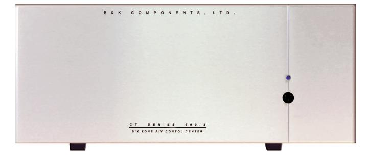
The CT Receivers are born from the heritage of twenty years experience in building high current, low distortion, high-end separates. Every design, concept, and tested part, unifies the critical listening vision, which happens when the music matters. With a B&K Multi-Zone receiver, any room may get the solid deep bass, the warmth, and the transparency of B&K. The CT Receiver is built by using 1% Metal Film resistors and computer grade electrolytic capacitors in order to create precision, linearity and dynamics that will reveal every detail of your source components. The ultimate reason to own B&K is the astonishing revolution in performance that you will enjoy. The CT Receiver is available in 17” (standard) and 19” (rack mount) faceplates with a black or silver color choice.
Built-In Intelligence
The CT Receivers work quietly behind the scenes to provide simple automation and flexibility for everyday live. The CT Receiver may instantly recall your favorite settings without any additional external automation systems by using unique Personal Action MacrosTM and B&K's SmartZoneTM system. The intelligence is built-in.
A Single Keypad in Each Room - Multi-Zone From One Central System
The CT300.3 provides three independent listening Zones whereas the CT 600.1/600.3 provides six. In each zone, the user may select sources, raise/lower volume, adjust bass/treble independently without affecting users in other zones! The CT Receivers give all the performance and ability that a dedicated stack of high-end separates would give a user in each room, without any of the visible clutter. The receiver and all shared sources may be concealed in a cabinet or rack in one central location. The user only needs a keypad to take control!
Connect Up to Nine Shared Sources
More than any other single feature, the nine input capability frees the system architecture from restriction. Nine inputs enable your system to grow in the future and accommodate any new technology. Built-in IR routing allows any of the source components to be identical, yet still be controlled independently without problems.
Video For The Entire House
The CT Receivers incorporate a composite video matrix, delivering a pristine picture to every room in the house. One touch to your remote control or keypad enables you to select different video sources.
Three AM/FM Tuners Allow Simultaneous Listening to Three Radio Stations
The CT Receiver Family offers a combination of internal AM/FM tuner configurations. The CT 600.1 includes 1 tuner, and the CT 300.3 and CT 600.3 include 3 tuners.
Six Dedicated Zone Inputs
Each zone has its own dedicated local Audio/Video source input. The dedicated inputs have the ability to sense an audio/video input. Once the audio/video input is detected, the zone will be switched automatically to the dedicated input. All the user needs to do is turn on the local source, simple!
B&K
SIMPLY BETTER!

|
3 |
CK 1.1 and CK1.2 Keypad Features and Benefits |
CK 1.1 and CK 1.2 Keypad Features and Benefits
Automation Everywhere!
Automate the Central System with Local TVs and Components
The CK1.2 keypad may control up to twenty devices or rooms with 5 hard buttons and four pages of custom labeled buttons per device. The CK 1.1 has 4 pages of custom labeled buttons and 5 hard buttons. Each button on either keypad may be programmed with a single IR command (pre-programmed from the database or learned) or it may be programmed with a macro with up to 190 steps, which may include IR commands, delays, and jumps to another page. A vast database of more than one thousand brands instantly programs IR Codes for most products. B&K Batch Learning does the rest in a fraction of the time of any other system. The CK 1.2 has input synchronization with the zone where it operates. The CK 1.1 and CK1.2 also have RS-232 status feedback. Macros may be programmed using the fastest macro programming method available (simply click on the button to make it a macro step). Once one keypad is programmed, the rest of the keypads may be cloned by downloading the program to each keypad. Each keypad stores its program on an EEPROM, so even if the power is lost, the memory is still good for up to 10 years.
Point Any Remote Control at the Keypad
The integrated IR pass-through sends the commands of any IR remote control to both local installed components and the central system. If your client wants to use a remote control in any room, they may simply point it at the B&K keypad.
Realtime Status Feedback to Keypads
Both the CK 1.2 and CK 1.1keypads will also display zone status when the backlight button is pressed. Realtime status feedback includes zone input name or radio station, volume, bass, treble and EQ settings. Additionally, a 12VDC status signal lights up the Green Status LED whenever the zone is on. CK 1.2 also offers RS-232 feedback from the CT Receiver so the keypads will be kept in sync with the source that is selected regardless of how it was selected (by a remote control, the front panel controls or the keypad itself).
Multiple Keypads In One Zone
Keypads may be used in a daisy chain application to accommodate up to 6 keypads per hardware zone. Any keypad has the ability to control any zone regardless of whether it is daisy chained (slaved) off another keypad. Slaved keypads are perfect for large rooms that require user interface at both ends. Keypads may be interconnected and used with up to 1000ft using CAT5-E cable.
B&K
SIMPLY BETTER!
4 |
|
CT Receiver Front Panel |
CT Front Panel (CT300.3 and 600.1/600.3)
1.Main Power Indicator.
2.Master Power Switch, used to disengage power to the CT Receiver. Normally, this switch is set to ON (in) which allows the power function of a remote or keypad to power the zones on or off. While the unit is in SLEEP the electrical consumption is reduced to about 35 watts.
1
2
Available faceplate options are 17” Black (standard), 17” Silver, 19” Rackmount Black and 19” Rackmount Silver. Unit shown is 17” Silver.
|
|
|
|
|
5 |
|
CT Receiver Back Panel |
|
|
||
1 |
2 |
|
3 |
|
|
|
|
|
|
|
|
|
|
|
|
|
|
 4
4
13
12 |
5 |
|
11 |
10 |
9 |
8 |
7 |
6 |
1.6 Keypad control connections provide 12VDC power, common ground, RS-232 transmit, IR Data IN and 12VDC control output triggers. The 300.3 has three keypad control connections. See page 19.
2.6 Zone Audio/Video Line outputs for external amplification (factory fixed output or may be set to variable output) and video monitors (1 per zone). On Screen Display (OSD) menu access is only provided through the zone A video output. See pages 17 and 18.
3.9 Buffered Audio/Video inputs and outputs for daisy-chain applications. See page 15.
4.AM and FM Antenna connection. Internally split for multiple tuners in the CT600.3/300.3. See page 23.
5.9 Audio/Video shared Source inputs that may be shared throughout all zones. See page 14.
6.9 Infrared emitter outputs for IR routing to source pieces. 1/8” (3.5mm) mini jack. See page 21.
7.Removable four position phoenix speaker connections. Speaker connections are 4 ohm stable. See page 16.
8.6 Zone dedicated Audio/Video inputs for local sources, one per zone. See page 14.
9.Link In and Link out for connecting multiple CT units. See page 25.
10.IR pass, IR In and All IR Out 1/8” minijack connections for IR routing. See page 25
11.RS-232 I/O and Ethernet RJ-45 for serial and network communication. See page 23
12.AC Power inlet and AC fuse. See page 13.
13.2 Common control connections with up to 24VAC or DC sensing on CT 600.1/600.3. One common control on CT 300.3. See page 22.
B&K
SIMPLY BETTER!
6 |
Accessories Guide |
|
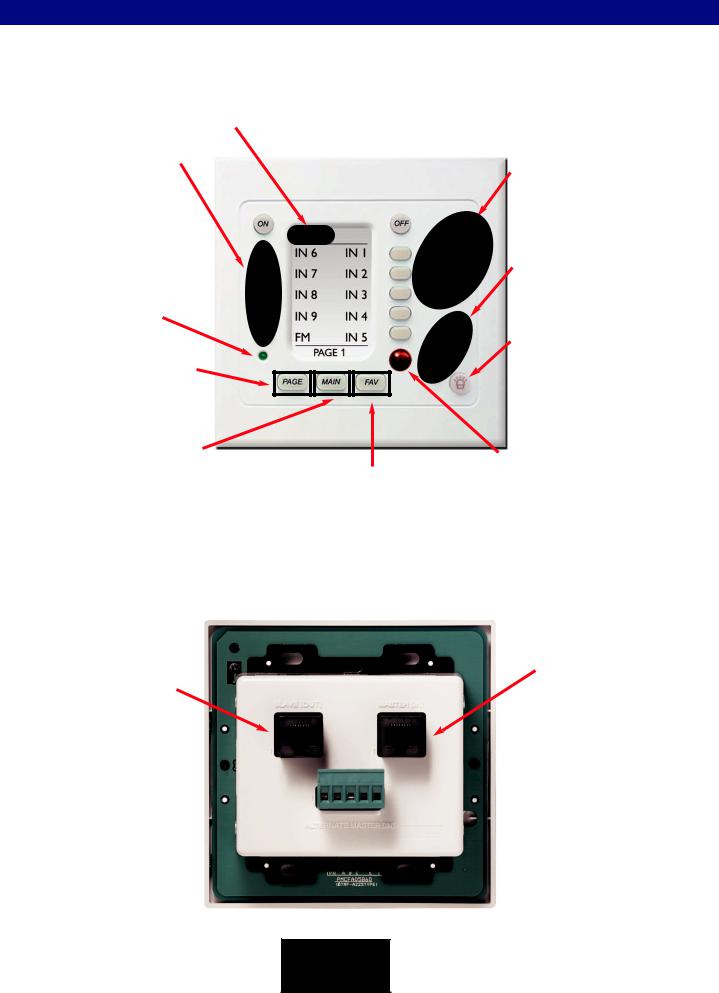
The CK1.2 Keypad Front Panel/Back Panel
sold separately
LCD Buttons - Names on the screen
change depending on what activity has been selected. For example, when CD is the activity, you’ll see the button names change to Play, Stop etc. so the source may be controlled.
Power LED lights up when this Zone/Room is ON. (Controlled by the 12V Control)
Page Button press to display any additional pages of functions.
Main Button
The Main button always returns to the Main Menu so that a may new device (activity) or zone may be selected.
Screen Title - Displays what Source is selected ( i.e. device or activity like “CD” or “SAT”). “Main” indicates the Main Menu for selecting a new device or activity.
Favorites Button
Availability to create up to five pages of radio station presets or source stations or macros.
Volume/Mute Buttons control the level of the audio.
Change Buttons - Change to the next channel, chapter, song or B & K sound preset; depending on the selected activity.
Backlight Button lights the keypad display and also recalls status feedback for that zone.
Status feedback will display input, radio station, volume, bass, treble and EQ settings.
Remote Control IR Receiver conceals an IR (Infrared) Sensor which relays commands from hand held IR remote control to the main unit and components connected to flashers.
Programming Jack - Behind the Faceplate
Four tabs hold the faceplate to the keypad chassis. To remove the faceplate, simply pull the faceplate off the keypad chassis. Once removed, the Programming Jack is revealed. Note: When testing keypad functionality, remove the programming jack. The keypad will not receive RS-232 communication while the programming jack is plugged in.
Slave [OUT]
Used when running multiple keypads in one zone or daisy chaining additional zones.
Master [IN]
The RJ-45 Master [IN] is used for the home run back to the
CT Receiver. RJ-45 termination allows the use of CAT-5
cable to be used for keypad installation.
 Alternate Master [IN]
The alternate master operates identically to the Master [IN]. Additionally, 12V controls or local source emitters may be terminated here. See Page 19
B&K
SIMPLY BETTER!
|
7 |
Accessories Guide |
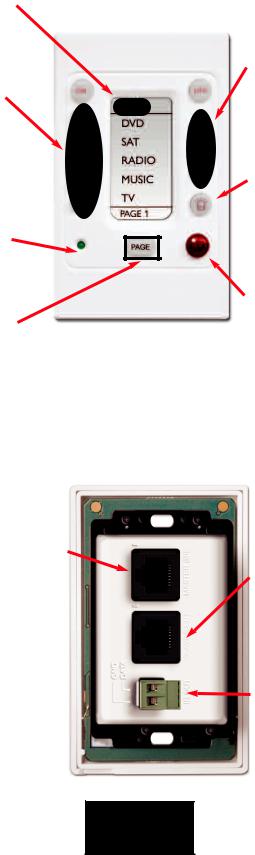
The CK1.1 Keypad Front Panel/Back Panel
sold separately
Screen Title - Displays a custom title edited from the LCD button editor. Under default programming it will display “Main”.
LCD Buttons - Names on the screen
change depending on what function is programmed on the button. For Example, if page 1 holds all controls for the CD player the LCD buttons will display Play, Stop, etc. so the device (CD in this case) may be controlled.
Power LED lights up when this Zone/Room is ON. (Controlled by the 12V Control)
Page Button press to display any additional pages of functions.
Programming Jack - Behind the Faceplate
Up, Down and Mute Controls
may be programmed for Volume and Mute control for the B&K zone or any device.
Backlight Button lights the keypad display and also recalls status feedback for that zone. Status feedback will display input, radio station, volume, bass, treble and loudness levels.
Remote Control IR Receiver conceals an IR (Infrared) Sensor which relays commands from hand held IR remote control to the main unit and components connected to flashers.
Four tabs hold the faceplate to the keypad chassis. To remove the faceplate, simply pull the faceplate off the keypad chassis. Once removed, the Programming Jack is revealed. Note: When testing keypad functionality, remove the programming jack. The keypad will not receive RS-232 communication while the programming jack is plugged in.
Master [IN]
The RJ-45 Master [IN] is used for the home run back to the CT Receiver. RJ-45 termination allows the use of CAT-5 cable to be used for keypad installation. See Page 19
B&K
Slave [OUT]
Used when running multiple keypads in one zone or daisy chaining additional zones.
IR OUTPUT
The IR Output may be used to connect an emitter directly from the keypad to a local IR source.
SIMPLY BETTER!
8 |
|
|
Accessories Guide |
||
|
||
|
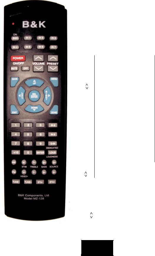
B&K CT Series MZ-128 Remote Controller Reference Sheet |
The MZ-128 Remote Controller has multiple useful functions:
1.The MZ-128 Remote Controller may be used to control and setup a CT Receiver.
2.The MZ-128 may be used as a source of IR for use in programming learning keypads, etc.
3.The MZ-128 may be set to source the B&K IR functions listed below, for code sets 000-128 and 999.
Setup the MZ-128 to use a discrete B&K code set:
1.Install 4 AAA batteries into the remote. Observe polarity.
2.Press and hold the B&K and MUTE buttons simultaneously for two seconds. The LED will light up solid red and stay illuminated.
3.Firmly press the desired B&K three digit code set. Always use three digits
(i.e. 0-1-1 Zone A)
4. Press the B&K button again to confirm setup. The red LED will blink three times when the IR code has been successfully programmed.
(MZ-128 Default Factory Code-Set is: 0-0-0 Whole House Control)
CODE SET 000-128
MZ-128 BUTTON |
B&K IR FUNCTION |
|
[POWER STATE] |
B&K |
POWER ON |
POWER |
POWER TOGGLE |
OFF |
POWER OFF |
|
[VOLUME] |
MUTE |
MUTE TOGGLE |
VOLUME |
MASTER VOL UP |
VOLUME |
MASTER VOL DOWN |
|
[TONE CONTROL] |
B+ |
BASS UP |
B- |
BASS DOWN |
T+ |
TREBLE UP |
T- |
TREBLE DOWN |
LOUD |
LOUDNESS TOGGLE |
|
[INPUT SOURCE] |
|
S+ |
SOURCE UP |
|
S- |
SOURCE DOWN |
|
V+ |
VIDEO SOURCE UP |
|
D-IN |
ZONE DEDICATED INPUT |
|
AM |
AM TUNER |
|
FM |
FM TUNER |
|
IN1 |
IN 1 OR [V1] |
|
IN2 |
IN 2 OR [V2] |
|
IN3 |
IN 3 OR [TV] |
|
IN4 |
IN 4 OR [DVD] |
|
IN5 |
IN 5 OR [CD] |
|
IN6 |
IN 6 |
OR [SAT] |
IN7 |
IN 7 |
OR [TAPE] |
IN8 |
IN 8 |
OR [V4] |
IN9 |
IN 9 |
OR [V5] |
|
[FAVORITE PRESET] |
PRESET |
FAVORITE PRESET UP |
PRESET |
FAVORITE PRESET DOWN |
MZ-128 BUTTON |
B&K IR FUNCTION |
|
[TUNER] |
AM |
SELECT THE AM BAND |
FM |
SELECT THE FM BAND |
TUNE + |
TUNE FREQUENCY UP |
TUNE - |
TUNE FREQUENCY DOWN |
STA + |
TUNER FAV PRESET UP |
STA- |
TUNER FAV PRESET |
M |
STEREO / MONO |
|
[NAVIGATION] |
MENU |
MENU UP/DOWN LEVEL |
LEFT |
LEFT OR BALANCE [L] |
RIGHT |
RIGHT OR BALANCE [R] |
SEL/ENTER |
SELECT OR ENTER |
UP |
UP |
DOWN |
DOWN |
SAVE |
SAVE |
EXIT |
TOTAL EXIT FROM ALL |
ZONE |
ZONE SELECT |
[NUMERIC]
00
11
22
33
44
55
66
77
88
99
+10 |
+10 |
CODE SET 999
MZ-128 BUTTON |
B&K IR FUNCTION |
|
[B&K ALL COMMANDS] |
ON/B&K/POWER |
ALL B&K POWER UP |
OFF |
ALL B&K POWER OFF |
VOLUME |
ALL B&K VOLUME UP |
VOLUME |
ALL B&K VOLUME DOWN |
0 |
ALL B&K VOLUME 0DB |
2 |
ALL B&K VOLUME -20DB |
4 |
ALL B&K VOLUME -40DB |
6 |
ALL B&K VOLUME -60DB |
MUTE |
ALL B&K MUTE TOGGLE |
|
|
Code-Set 128 Simply Explained
Code-set 128 is a special code-set which allows individual control of the Hardware Zone that the IR data is received by. It will not function when received by the unit’s front panel i.e. Two keypads are plugged into Zone A&B’s Control I/O ports, when the remote comes into IR view of the keypad in Zone A, the 128 Code-Set remote will only control Zone A, when in Zone A. Take that same remote into Zone B and it will only control Zone B.
B&K
SIMPLY BETTER!
|
9 |
Accessories Guide |
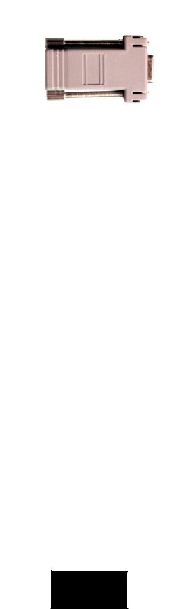
DB-9 to RJ-45 Adapter P/N:13290 (Included)
Included with any CT Receiver product, this adapter allows easy interface between a PC and any B&K product using a standard terminated CAT-5 cable. The adapter plugs into the serial port of the PC.
BK CT Series CD P/N: 14069
B&K offers PC based setup software (BK Suite) for all of its receivers and preamplifiers . BK Suite is designed to expedite the setup process by allowing users to edit presets, save files, and create templates virtually before downloading them to the unit. The BK CT Series CD includes programming software for B&K receivers/processors, the SR10.1 remote control and CK1.2/CK1.1Keypad Editors, B&K Hardware Quick Tools for CT Receivers and the HD6 and the Flash File Download for updating the HD6, CT 600.1,CT 600.3 and CT 300.3. A PDF library of the B&K product line is also included with BK Suite. The library includes all B&K product manuals, systems diagrams, and reference material for RS-232 communication. Additional information and all programs are available on the web at www.bkcomp.com.
***- PC requirements - 128MB RAM, Pentium grade or better processor, Windows XP is the recommended operating system. (Exception - BK Suite not supported on Windows NT) ***
B&K
SIMPLY BETTER!
10 |
|
|
Installation and System Diagrams |
||
|
||
|
Installation and System Diagrams |
|
|
Zone F |
|
|
Zone C |
|
|
|
Keypad |
|
|
||
|
|
|
|
Keypad |
||
|
|
|
|
|
|
|
|
|
|
|
|
|
Zone B |
|
|
|
|
|
|
|
|
|
|
|
|
|
|
|
|
Zone E |
||||
|
|
Keypad |
|
|
Keypad |
|
|
|
|
|
|
|
Zone A |
|
|
|
|
|
|
|
|
|
|
|
|
|
|
|
|
|
|
|
|
|
|
|
Zone D |
||||
|
|
Keypad |
|
|
|
Keypad |
|
|
|
|
|
|
|
|
|
|
|
|
|
|
Composite Video
Left Audio
Right Audio
Zone
Speaker
Connections
Positive
Negative
Zone F |
Zone E |
Zone D |
Zone C |
Zone B |
Zone A |
Speakers |
Speakers |
Speakers |
Speakers |
Speakers |
Speakers |
See the following pages for details describing
B&K installation procedures.
SIMPLY BETTER!

|
11 |
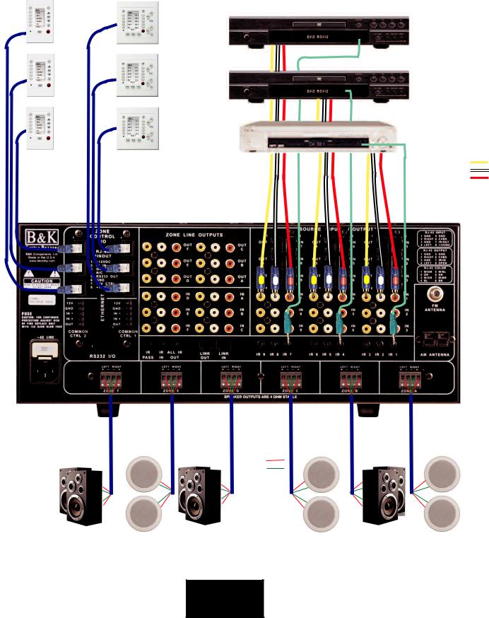
Basic System Hookup |
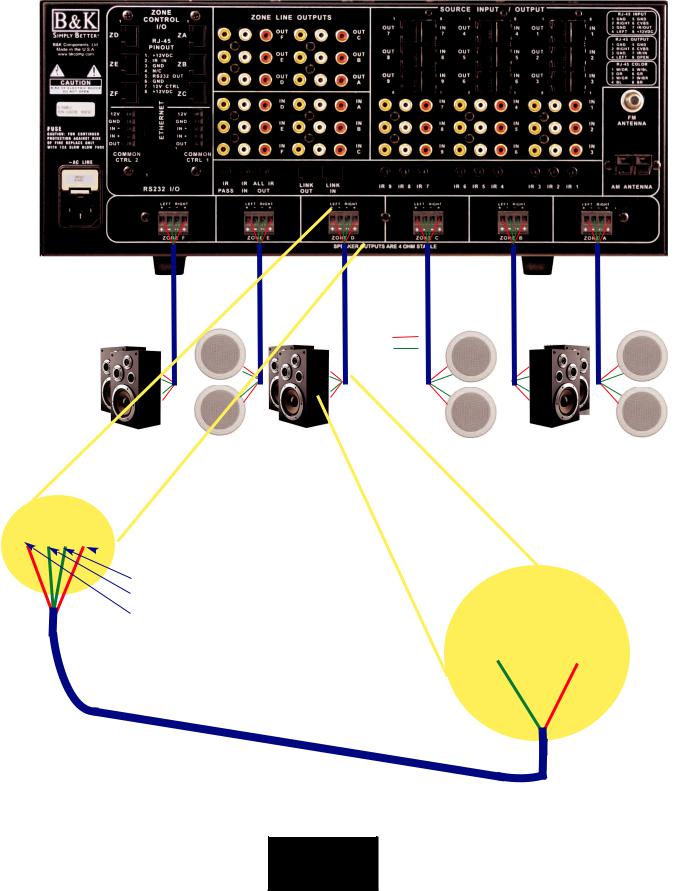
Basic CT Receiver & Keypad System Hookup
Keypads connect to the Zone Control terminals on the CT Receiver using CAT-5 cable. Composite video is used for video distribution, usually RG-6 or better.
|
|
|
|
|
|
|
|
|
|
|
|
|
|
Zone F |
|
|
|
|
|
Zone C |
||
|
|
|
|
|
|
|
|
|
|
|
||||||||||||
|
|
Zone F |
|
|
|
|
|
|
|
|
|
|
Monitor |
|
|
|
|
|
Monitor |
|||
|
|
|
|
Zone C |
|
|
|
|
|
|
|
|
||||||||||
|
|
Keypad |
|
|
|
|
|
|
|
|
|
|
|
|
|
|
||||||
|
|
|
|
Keypad |
|
|
|
|
|
|
|
|
|
|
|
|
||||||
|
|
|
|
|
|
|
|
|
|
|
|
|
|
|
|
|
|
|||||
|
|
|
|
|
|
Zone B |
|
|
|
Zone E |
|
|
|
|
|
Zone B |
||||||
|
|
|
|
|
|
|
|
|
|
|
|
|
|
|||||||||
|
|
|
|
|
|
|
|
|
|
|
|
|
|
|||||||||
|
|
Zone E |
||||||||||||||||||||
|
|
|
|
|
|
|
|
|
|
|
Monitor |
|
|
|
|
|
Monitor |
|||||
|
|
Keypad |
|
|
Keypad |
|
|
|
|
|
|
|
|
|
||||||||
|
|
|
|
|
|
|
|
|
|
|
|
|
||||||||||
|
|
|
|
|
|
Zone A |
|
|
|
|
|
|
|
|
|
|
|
|
||||
|
|
|
|
|
|
|
|
|
|
|
|
|
|
|
|
|
|
|||||
|
|
|
|
|
|
|
|
|
|
|
|
|
|
|
|
|
|
|||||
|
|
|
|
|
|
|
|
|
|
|
|
|
|
|
|
|
|
|||||
|
|
Zone D |
|
|
|
Zone D |
|
|
|
|
|
Zone A |
||||||||||
|
|
Keypad |
|
|
|
Keypad |
|
|
|
|
|
|
|
|
|
|||||||
|
|
|
|
|
|
|
|
|
|
|
|
|
|
Monitor |
|
|
|
|
|
Monitor |
||
|
|
|
|
|
|
|
|
|
|
|
||||||||||||
|
|
|
|
|
|
|
|
|
|
|
|
|
|
|
|
|
|
|
|
Composite Video |
|
|
|
|
|
|
|
|
|
|
|
|
|
|
|
|
|
|
|
|
|
|
|
||
|
|
|
|
|
|
|
|
|
|
|
|
|
|
|
|
|
|
|
|
|
||
|
|
|
|
|
|
|
|
|
|
|
|
|
|
|
|
|
|
|
|
|
||
|
|
|
|
|
|
|
|
|
|
|
|
|
|
|
|
|
|
|
|
|
||
|
|
|
|
|
|
|
|
|
|
|
|
|
|
|
|
|
|
|
|
Left Audio |
|
|
|
|
|
|
|
|
|
|
|
|
|
|
|
|
|
|
|
|
|
|
|
||
|
|
|
|
|
|
|
|
|
|
|
|
|
|
|
|
|
|
|
|
Right Audio |
|
|
|
|
|
|
|
|
|
|
|
|
|
|
|
|
|
|
|
|
|
|
|
||
|
|
|
|
|
|
|
|
|
|
|
|
|
|
|
|
|
|
|
|
|
|
|
|
|
|
|
|
|
|
|
|
|
|
|
|
|
|
|
|
|
|
|
|
|
|
Zone
Speaker
Connections
Positive
Negative
Zone F |
Zone E |
Zone D |
Zone C |
Zone B |
Zone A |
Speakers |
Speakers |
Speakers |
Speakers |
Speakers |
Speakers |
B&K
SIMPLY BETTER!

12 |
|
|
|
|
|
|
|
Installation Considerations |
|||||||
|
|||||||
|
Installation Considerations |
||||||
|
|
|
|
|
|
||
|
|
|
|
|
|
||
|
|
|
|
CAUTION |
|
||
|
|
|
R I S K O F E L E C T R I C S H O C K |
|
|||
|
|
|
|
||||
|
|
|
|
D O N O T O P E N |
|
||
|
Placement and Ventilation |
||||||
|
The CT Receiver incorporates built in power amplifiers and requires at least 3" of free air space above the |
||||||
|
unit. If built into a rack, please insert at least one rack space of vent panel immediately above the unit. |
||||||
|
Default Operation |
||||||
|
The factory default settings of a B&K CT Receiver are designed for simplicity and functionality right out of the |
||||||
|
box! Default settings will allow for simple functions such as zone power, volume control, input changing and |
||||||
|
video connections to be checked as soon as they are connected. No programming required! |
||||||
|
Connection Strategy |
||||||
|
Installation of a complex A/V system may be a daunting task at first glance. However, the secret to a great |
||||||
|
looking and easy to service installation is to be as deliberate as possible. Make the installation SERVICE- |
||||||
|
ABLE as well as neat! Dress the wires in groups according to purpose: |
||||||
|
·AC Power lines tied together and attached to the cabinet/rack on the opposite side of the signal |
||||||
|
cabling. Any component without enough slack in the power wire to enable rotating it or extracting it |
||||||
|
should have its length extended with a dedicated extension cord. |
||||||
|
·Speaker wires tied together and attached to the cabinet/rack on the opposite side of AC Power lines. |
||||||
|
·Antennas should be routed so that they may be re-positioned later. |
||||||
|
·IR emitters should be routed and tied down, but NOT attached to source components. Remember, |
||||||
|
emitter position is best done with the system powered up! Emitter wires may safely be run adjacent to |
||||||
|
AC Power cables. |
||||||
|
·Combine Keypad/IR Sensor cables together with any Dedicated Zone Input cables that originates in |
||||||
|
another zone. Tie each Zone Control cable together with its dedicated source. Tie everything |
||||||
|
together; make sure there is a service loop of free cable and dress on the opposite side of the AC |
||||||
|
Power cables. |
||||||
|
·Combine all cables coming from the sources, label each cable and connect them to the nine inputs. |
||||||
|
·Combine all buffered outputs and connect to additional preamplifiers/receivers in the system. |
||||||
|
·If you are utilizing any external power amps, combine the zone line outputs and connect to each |
||||||
|
amplifier in turn. |
||||||
|
Always leave enough slack at the ends of the cable so that the CT Receiver may be rotated and pulled out of |
||||||
|
the shelf. Do not leave wires tied down so tightly that the components are unable to be rotated or extracted |
||||||
|
from the rack. |
||||||
|
|
|
|
|
|
|
|
|
|
B&K |
|
|
|||
|
|
|
|
|
|
|
|
SIMPLY BETTER!

|
13 |
Power Connections |
AC Power and Line Fuse
Before connecting any A/V cables, verify that the CT Receiver powers up. Check functionality of the receiver by connecting the AC power cord and powering on the receiver using the main power button, the front panel LED should now be lighted. After 45 seconds, the receiver has finished it’s boot process. Turn off the main power button and disconnect the AC power cord. Connect all A/V and other interconnect cables and re-connect the AC power cord. The CT Receiver connection process should now be complete.
Checking the AC Power fuse:
1.Power off the unit and unplug the power cord.
2.Push up on the fuse release tab.
3.Pull the entire fuse holder out.
4.Remove the fuse from the fuse holder and measure the fuse with a meter. It is not possible to know if the fuse is
blown by looking at it.
5. The CT 600.3/600.1 requires a 12A Slow-Blow type fuse. The CT 300.3 requires a 8A SlowBlow type fuse.
Replace only with fuse of same type and value.
Caution! A blown fuse is usually an indicator of an installation or service problem. If the fuse continues to fail, the installer should contact B&K Components Customer Service at 716-656-0026 or contact an authorized B&K Service Center for assistance.
Speaker Connections for CT Receiver
The CT Receiver connects to speakers using 4 position plug-in Phoenix connectors. Speaker wires are home run from each zone to the back panel of the CT Receiver. Unplug the connector from the rear of the receiver, strip the speaker wire approximately ¼" and insert the bare end into the gate on the connector. Use a small flat blade screwdriver to tighten the con-
nection to each conductor. Connectors accommodate up to 12-gauge wire.
Make sure to observe polarity as you hold the connector upside down to connect Left and Right as shown. Two guide tabs also insure proper orientation.
B&K
SIMPLY BETTER!
14 |
|
Source Connections |
Shared Source Inputs
Any source that is desired to be shared throughout the system will connect to one of the 9 A/V Source Inputs. Nine sources may be "shared" throughout any zone in the entire system. Internal tuners in the CT receiver products do not utilize an input. Each of the nine shared sources should be connected as follows:
CT Receiver Connection
Plug the analog audio L&R, composite video, and the IR emitter into the back panel.
Source
Source Connection
Use the analog audio and composite video from the source. Composite video and analog audio may be distributed throughout the system. Digital audio may be passed through the composite video inputs and outputs See Page 15.
Mount the IR Emitter on the front panel, in front of the IR receptacle of the source.
Dedicated (Local) Source Inputs
Dedicated source inputs are used for local sources that are dedicated only to that individual zone. Typically this feature is appropriate for sources that are physically located in the zone, such as DVD players or satellite boxes in bedrooms or dens. By running well shielded audio and video cable from the local source back to the CT Receiver, the user may utilize the auto-sense capability, which is built into these inputs. The CT Receiver will immediately auto-detect the audio or video signal from a Dedicated input and switch that zone to its dedicated input. By default, this feature is set to on; however it may be turned off to add an additional manually selectable input for that particular zone. Dedicated source inputs are identified on the back panel by the zone to which they are associated, i.e. IN A, IN B, etc. When auto-detect is used, the CT Receiver will store previous state of the zone before the Dedicated input detected a signal. Therefore, when the dedicated signal is switched off, the zone is returned to its previous state.
CT Receiver Dedicated
Inputs (Back Panel)
Dedicated inputs require an additional run from the zone to the CT Receiver for the audio/video connections.
B&K
SIMPLY BETTER!
|
15 |
Buffered Outputs |
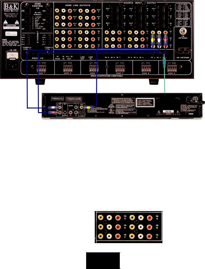
Buffered Outputs
Line level, impedance matched, (buffered) outputs are provided in order to pass source signals from one unit to another. Each of the 9 shared A/V inputs has a buffered output. These outputs are buffered in order to minimize signal degradation as the signal passes from unit to unit in series. Essentially they eliminate the need for Y-cables. The Buffered outputs will primarily be used for sharing of sources between other whole house units or home theater systems.
Note: When setting up a CT System, connect all audio/video inputs and respective infrared emitters to the first CT Receiver. Expand the system by linking multiple CT Receivers with standard CAT-5 cabling. Connect one CAT-5 cable per shared input (9 total) and 1 CAT-5 cable from “Link Out” to “Link In” See page 25.
Digital Audio Connection
When video is not needed to be routed, the CT Receiver composite video inputs/outputs may be used to route coax digital audio. Simply connect the digital coax connection from the source device into the shared or dedicated video inputs. The CT zone video outputs will now switch digital audio to a surround processor.
Ref 50 S2
Source
B&K
SIMPLY BETTER!
16 |
|
|
|
|
CT Receiver Speaker Connections |
||||
|
||||
|
Example CT Receiver Six Zone Speaker Connections |
|||
|
|
|
|
|
|
|
|
|
|
Zone
Speaker
Connections
Positive
Negative
|
|
|
|
|
|
|
Zone F |
Zone B |
Zone D |
Zone C |
Zone E |
Zone A |
|
Speakers |
Speakers |
Speakers |
||||
|
Speakers |
|
|
Speakers |
|
Speakers |
 [R+] Right Positive Speaker Output (Red Wire)
[R-] Right Negative Speaker Output (Green Wire)
[L+] Left Positive Speaker Output (Red Wire)
[L-] Left Negative Speaker Output (Green Wire)
[-] Negative Speaker Input (Green Wire) [+] Positive Speaker Input (Red Wire)
Amp channels are 4W stable. B&K
SIMPLY BETTER!
|
17 |
Zone Line Outputs |
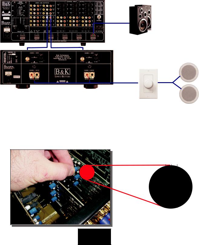
Connecting an External Amplifier
Zone line outputs are used to run the audio and/or video into each zone. Line level audio outputs are supplied for each zone in order to provide a means for external amplification in any zone. These line outputs may be configured for either fixed at line level or variable to match the volume level of the receiver (See Below). The Zone Line outputs will not output audio when the zone is off. By factory default on a CT 600.3/600.1, the line outputs for zones A, B and C are set to variable output and zones D,E and F are set to line level fixed output. By factory default on a CT 300.3, the line outputs for zones A and B are set to line level fixed output and zone C is set to variable. An external volume control is needed for line level fixed applications.
Ref 200.2 S2 amplifier
Changing Line Level Outputs From Fixed to Variable
An internal jumper is used to change the zone RCA outputs between line level fixed or variable. This configuration is most beneficial when a zone is to be used with additional external amplification. Open the chassis and locate the blue jumper on the audio card for the Zone Line Outputs. The jumpers are in line with each channel on the back panel. The right position is fixed (F) line level, the left position is variable (V) volume control. When the jumper is set to variable, the volume level of the output will be matched with the volume level of the receiver amplifier output. The jumper has the ability to change either the left (L) or the right (R) side of each zone if desired. An external volume control is required for a fixed output application.
!
Fixed
Left
Variable
V L F V R F
Fixed
Right
Variable
B&K
SIMPLY BETTER!
18 |
|
|
|
|
|
|
|
|
Zone Line Outputs |
|
|||
|
|
|
|
|||
|
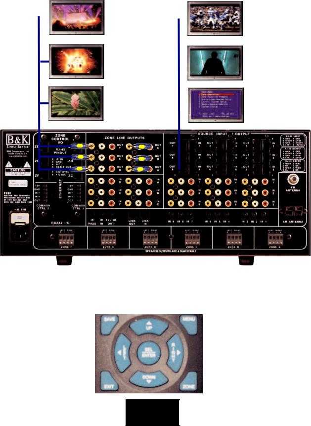
Composite Video Outputs |
|
||||
|
Composite video outputs supply video to monitors in each zone. Zone A's video output provides access to |
|||||
|
the on screen display, which is used for unit setup. The setup menu is only accessible through Zone A’s |
|||||
|
composite video output. The video signal will shut off when the zone is shut off. |
|
||||
|
|
|
Zone F |
Zone C |
||
|
|
|
Monitor |
|
|
Monitor |
Zone E |
|
Zone B |
Monitor |
|
Monitor |
|
Zone D |
|
Zone A |
||
Monitor |
|
Monitor |
||
|
||||
|
|
|
|
|
|
|
|
|
|
|
|
|
|
|
Menu System
To access the menu, make sure you have a monitor coming from the zone A video out. Then push MENU on the MZ-128 remote. Use the UP, DOWN, LEFT, RIGHT and SEL buttons in the center of the remote along with the number keys to go through the menu functions.
B&K
SIMPLY BETTER!
|
19 |
CK1.2 Keypad Connections |
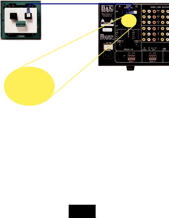
Keypad Connections
Keypads connect to the CT Receiver at the Zone Control I/O Terminals. Termination of the Keypad cables to the Control Terminals is done by a straight through CAT-5 cable.
If needed, the pin out configuration of the keypad wiring is located on the back of the CT receiver.
Each of the 5 functions for the keypad control ports are defined as follows:
+12VDC - Use this terminal to power the sensors and keypads for this zone. Each control card is limited to 1 amp capacity per three zones in each vertical array. See the next page for examples.
GND - Use this terminal as a common ground for data, control and power.
RS-232 XMIT - This terminal transmits RS-232 information. This pin allows RS-232 status feedback to the CK1.2 keypad or other RS232 capable devices. It may be configured with Tab 11 of BK Suite. The CT Receiver may not receive RS-232 via this terminal.
DATA IN - This terminal is an IR data port feeding both the flasher port of the selected input (unless routing is set to ALL) and the main CT microprocessor for B&K commands.
CTRL OUT - The 12VDC 200mA outputs are used to control external amplifiers, relays, screens or devices that activate when a voltage is detected. The default action is that the voltage is ON when the Zone is ON, OFF when the zone is off. This is controlled by going into the Advanced FULL Setup Tab 9 in BK Suite. The 12VDC controls may be modified to the following choices:
Zone On |
The 12V |
Control Out is on if the corresponding Zone is on (This is Default). |
Zone Active |
The 12V |
Control Out will turn on only if the Zone is on AND the CT Receiver may |
|
detect an audio or video signal on the selected input for that hardware zone. |
|
Zone Off |
The 12V |
Control Out will turn on only if the corresponding hardware Zone is off. |
Selected Input |
The 12V |
Control Out is on only if this input is selected (switched to) by the user. |
|
Note - when this option is selected, the input check boxes are active. Check all inputs that are desired to |
|
|
turn on the Zones Control Out. |
|
B&K
SIMPLY BETTER!
20 |
CK 1.2 Keypad Connections |
|
Adding Additional Keypads in the Same Zone
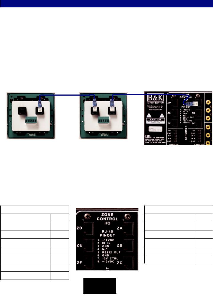
When rooms are interconnected or are open to each other (for example: interconnecting family room, kitchen, and dining areas are common in many homes) you may opt to expand a zone to include several rooms. Many keypads may be connected in a daisy chain from the master keypad in that zone. The master is the keypad which is home run back to the CT Receiver. To daisy chain keypads, simply connect a straight through CAT-5 cable terminated into RJ-45 between the two keypads. All the chained keypads need be programmed separately . Daisy-chained keypads may be programmed for independent zone control using the appropriate code-set.
The home run (master) keypad is connected using the MASTER [IN] on the keypad back panel. From the Master Keypad's SLAVE[OUT] connect to the second keypad's MASTER [IN]. You may continue the daisychain to as many as four keypads per zone control terminal. When programming daisy chained keypads, each keypad must be programmed separately. Do not program a slaved keypad while it is physically connected to the master keypad.
POWER SUPPLY IS CURRENT LIMITED TO 1 AMP PER EVERY THREE ZONES
The six zone receivers have two zone/controller cards, each is identical to the single controller card in a three zone receiver. Each card has its own independent 1 amp power supply with built in current limiting protection. It is not allowed to draw more than 1 amp from each of the cards (a card is the vertical strip of zone and common control connections). The control outputs are current limited to 200mA.
The CT 300.3 has one power supply card for keypads, IR sensors and 12VDC control outs. Anything connected to the +12V zone keypad output, a zone control out or a common control out must have its power consumption noted and added up. The total must not draw more than 1 amp for a CT 300.3.
LEFT CONTROLLER CARD |
RIGHT CONTROLLER CARD |
||
Fam Room Keypad |
75 mA |
Living Room Keypad |
75 mA |
Fam Room Sensor |
50 mA |
Patio Keypad |
75 mA |
Family Rm Screen Relay 200 mA |
Den Keypad |
75 mA |
|
Kitchen Keypad |
75 mA |
Den Sensor |
50 mA |
Bedroom Keypad |
75 mA |
|
|
Bedroom TV Lift |
200 mA |
TOTAL |
275 mA |
TOTAL |
675 mA |
|
|
B&K
SIMPLY BETTER!
|
21 |
IR Emitter Outputs |
IR Flasher Emitter Output
Each of the nine shared sources may be controlled from any zone in the system using the CT Receiver built in IR routing circuitry. By default, when the IR Flasher outputs are set to “selected input,” IR will route from the keypad terminal to the IR output for only the input that is selected for that zone. This allows identical source components to be used independently in the system. The flasher outputs may also be set to all input configuration,where all 9 IR outputs will flash simultaneously. The IR outputs are compatible with any standard 1/8” (3.5mm) miniature flasher/emitter from Niles, Xantech, Elan, Sonance or Speakercraft, etc. The IR outputs operate at 5V and may supply up to 10mA of current (475W internal output resistance). All outputs accommodate a wide range of carrier frequencies used in current source pieces. Make sure to use IR shields when using multiple identical sources in the same rack.
By factory default, the IR outputs are set to ‘SELECTED INPUTS’ where IR routing is taking place.
Local IR Source Control
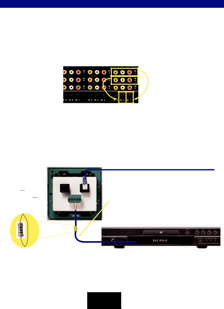
Local source control is accomplished by connecting IR emitters to the Alternate Master [IN] of the keypad. Local control is not limited to one source, up to four IR emitters may be wired in series directly from the keypad. NOTE: Additional resistance will need to be added when running emitters directly from the keypad. Resistance may vary depending on the distance of the wire and the size of the wire. Typical in line resistance will range from 100W (for long runs) to 500W (for short runs). If resistance is not added, control of shared sources may be lost. 12V Control voltages for local amplifiers or other voltage sensing devices may also be terminated directly to the keypad’s Alternate Master [IN] using the 12V control and ground.
Alternate Master Pin on CK 1.2
1.+12VDC IN
2.GROUND
3.RS-232 RECEIVE 4.KEYPAD DATA OUT
5.STATUS IN
To CT Back Panel 
Standard 2 conductor 16 gauge speaker wire is ideal for long runs from the keypad to a Local TV or device using an IR emitter. Utilizing CAT-5 cable will also work well.
Note: Additional resistance may be needed to be inserted in line when running an IR flasher directly off a keypad. Resistance will vary depending on length of run usually between (100W - 500W). The resistor needs to be wired in series with the flasher. The resistor may either be on the + or - side of the connection. Additional resistance is needed if the keypad is not able to control the shared sources connected to the 9 IR outputs.
B&K
Multiple emitters should be connected in SERIES!
Most common brands of emitter may be used, however all Emitter output more consistent levels when connected in series. Parallel connections may work “some of the time”. Series connections are recommended for consistent operation!
SIMPLY BETTER!
Loading...