


QB884H
Part No. 430316 Form No. F083100A
Page 1 of 12
3
Specifications
UNIT SIZE:
OVERALL LENGTH: 51.75"(1.31m) OVERALL WIDTH 28.5" (0.72m) OVERALL HEIGHT 39" (0.99m)
1
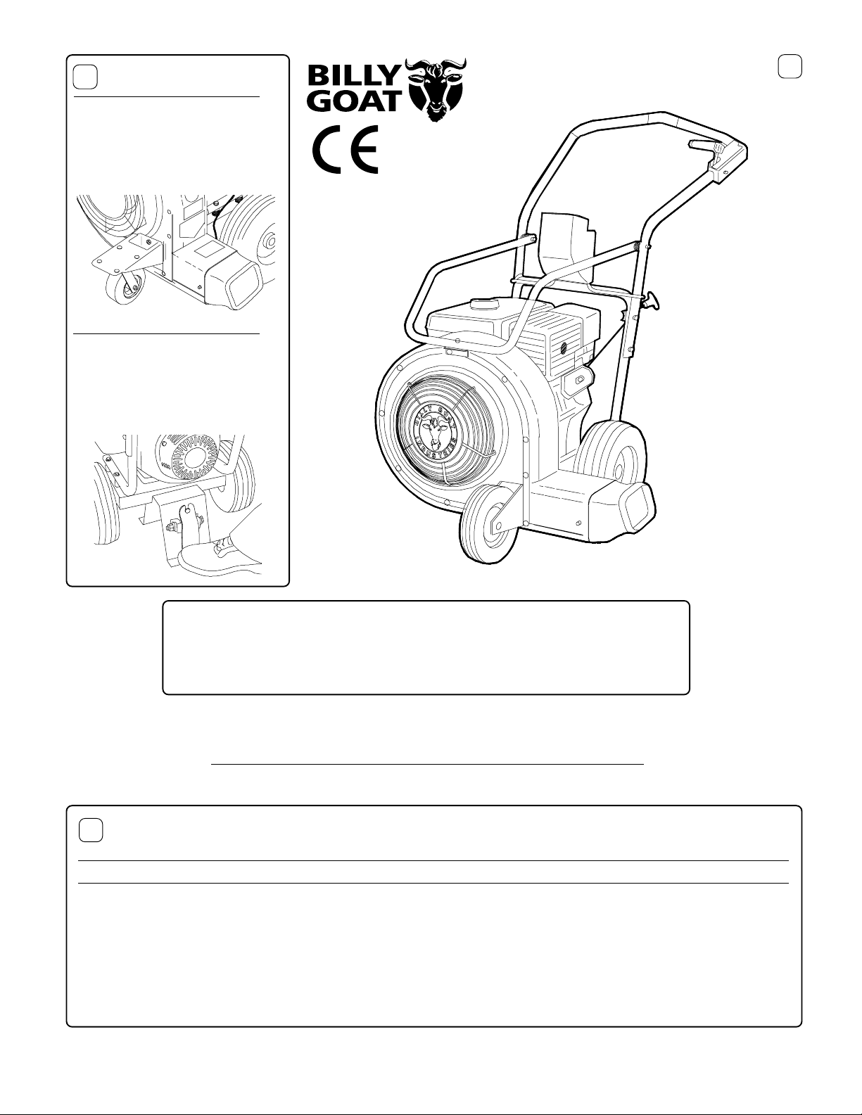
Thank You for Selecting
Operator Owner's Manual
The Powerful
QUIET BLOW
® BLOWER
QB884H, QB1004, QB1104H
For Models:
QB 884H QB 1004 QB 1104H
En
g
ine: HP 8.0 HP
(
5.97 kW
)
10.0HP
(
7.45kW
)
11.0HP
(
8.2kW
)
En
g
ine:T
y
pe HONDA OH V B & S INTEK I/C HONDA OH V
En
g
ine: Fuel cap. 6.4
q
t.
(
6.1 L
)
4.0
q
t.
(
3.8 L
)
7.4
q
t.
(
7.0 L
)
En
g
ine: Oil Cap. 1.16
q
t.
(
1.1 L
)
0.875
q
t.
(
0.8L
)
1.2
q
t.
(
1.13L
)
Wei
g
ht: Unit 136 #
(
61.7 K
g)
136 #
(
61.7 K
g)
152 #
(
68.9 K
g)
Wei
g
ht: S hippin
g
155 #
(
70.3 K
q)
155 #
(
70.3 K
q)
169 #
(
76.7 K
g)
En
g
ine W ei
g
ht: 52.0 #
(
23.6 K
g)
52.0 #
(
23.6 K
g)
68.4 #
(
31.0 K
g)
OPTIONAL ACCESSORIES
2
To improve maneuverability
on hard paved surfaces.
CASTER KIT
P/N 430291
For use on truck or trailer to
provide quick hold down for
your QB.
HOLD DOWN KIT
P/N 430299
Patent Pending
Part No. 430316 Form No. F083100A
WARNING: DO NOT
1. DO NOT run engine in an enclosed area.
Exhaust gases contain carbon monoxide, an
odorless and deadly poison.
2. DO NOT place hands or feet near moving
or rotating parts.
3. DO NOT store, spill or use gasoline near
an open flame, or devices such as a stove,
furnace, or water heater which use a pilot
light or devices which can create a spark.
4. DO NOT refuel indoors where area is not
well ventilated. Outdoor refueling is recom-
mended.
5. DO NOT fill fuel tank while engine is
running. Allow engine to cool for 2 minutes
before refueling. Store fuel in approved
safety containers.
6. DO NOT remove fuel tank cap while
engine is running.
7. DO NOT operate engine when smell of
gasoline is present or other explosive
conditions exist.
8. DO NOT operate engine if gasoline is
spilled. Move machine away from the spill
and avoid creating any ignition until the
gasoline has evaporated.
9. DO NOT transport unit with fuel in tank.
10. DO NOT smoke when filling fuel tank.
11. DO NOT choke carburetor to stop engine.
Whenever possible, gradually reduce engine
speed before stopping.
12. DO NOT run engine at excessive speeds.
This may result in injury & /or damage
to unit.
Page 2 of 12
21. DO NOT touch hot muffler, cylinder, or
fins because contact may cause burns.
22. DO NOT run engine without air cleaner
or air cleaner cover.
23. DO NOT operate during excessive
vibration!
24. DO NOT leave machine unattended
while in operation.
25. DO NOT park machine on a steep grade
or slope.
WARNING: DO
1. ALWAYS DO remove the wire from the
spark plug when servicing the engine or
equipment TO PREVENT ACCIDENTAL
STARTING.
2. DO keep cylinder fins and governor parts
free of grass and other debris which can
affect engine speed.
3. DO pull starter cord slowly until resistance
is felt. Then pull cord rapidly to avoid
kickback and prevent hand or arm injury.
4. DO examine muffler periodically to be
sure it is functioning effectively. A worn or
leaking muffler should be repaired or
replaced as necessary.
5. DO use fresh gasoline. Stale fuel can gum
carburetor and cause leakage.
6. DO check fuel lines and fittings frequently
for cracks or leaks. Replace if necessary
7. Follow engine manufacturer operating
and maintenance instructions.
8. Inspect machine and work area before
starting unit.
OPERATO R
VIBRATION
Vibration levels at the operators handles were
measured in the vertical, lateral, and longitudinal
directions using calibrated vibration test equipment.
T ests were performed on 04/10/2000 under the
conditions listed:
WIND DIRECTION:
HUMIDITY:
TEMPERATURE:
BAROMETRIC PRESSURE:
GENERAL CONDITION:
GENERAL CONDITION:
WIND SPEED:
WIND DIRECTION:
HUMIDITY:
TEMPERATURE:
BAROMETRIC PRESSURE:
5
SAFETY INSTRUCTIONS 2
GENERAL SAFETY 3
ASSEMBLY 3
LABELS 4
P ARTS BA G & CONTROLS 4
OPERATION 5-6
MAINTENANCE 7-9
PARTS DRAWING & LIST 10-11
TROUBLESHOOTING 12
WARRANTY PR OCEDURE 12
TABLE OF CONTENTS
6
7
VIBRA TION LEVELS 3.2 g
8
SOUND
SOUND TESTS
P ARTLY SUNNY
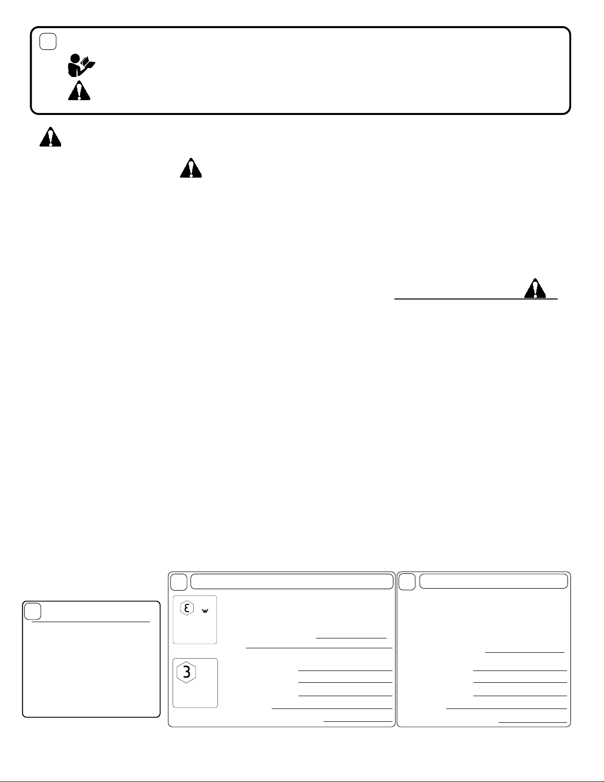
IN THE INTEREST OF SAFETY
BEFORE ST A R TING ENGINE, READ AND UNDERST AND THE “ENTIRE OPERATOR'S MANUAL &
ENGINE MANUAL.”
THIS SYMBOL MEANS WARNING OR CA UTION. DEATH, PERSONAL INJURY AND/OR PROPERTY
DAMAGE MAY OCCUR UNLESS INSTRUCTIONS ARE FOLLOWED CAREFULLY.
WARNING!
The engine exhaust from this product contains chemicals known to the State of California to cause
cancer, birth defects or other reproductive harm.
PARTLY SUNNY
WIND SPEED:
49%
29.94
S.E.
9
60°
60°
9
S.E.
49%
29.94
Sound tests were conducted on model QB1004 in
accordance with 79/113/EEC and were performed
on 04/10/2000 under the conditions listed:
13. DO NOT tamper with governor springs,
governor links or other parts which may
change the governed engine speed.
14. DO NOT tamper with the engine speed
selected by the engine manufacturer.
15. DO NOT check for spark with spark plug
or spark plug wire removed. Use an
approved tester.
16. DO NOT crank engine with spark plug
removed. If engine is flooded, place throttle
in “FAST” position and crank until engine
starts.
17. DO NOT strike flywheel with a hard
object or metal tool as this may cause
flywheel to shatter in operation. Use proper
tools to service engine.
18. DO NOT operate engine without a
muffler. Inspect periodically and replace, if
necessary. If engine is equipped with
muffler deflector, inspect periodically and
replace, if necessary, with correct deflector.
19. DO NOT operate engine with an
accumulation of grass, leaves, dirt or other
combustible material in the muffler area.
20. DO NOT use this engine on any forest
covered, brush covered, or grass covered
unimproved land unless a spark arrester is
installed on the muffler. The arrester must
be maintained in effective working order by
the operator. In the State of California the
above is required by law (Section 4442 of
the California Public Resources Code).
Other states may have similar laws. Federal
laws apply on federal lands.
91
L
A
L
A
p
99
Part No. 430316 Form No. F083100A
Page 3 of 12
For your safety and the safety of others, these
directions should be followed:
Use of Ear Protection is recommended while
operating this machine.
Do not operate this machine without first reading
owner's manual and engine manufacturer's manual.
Use of Eye and breathing protection is recom-
mended when using this machine, especially in
dry and dusty conditions.
GENERAL SAFETY
9
PACKING CHECKLIST
11
PUT OIL IN ENGINE BEFORE STARTING
Read all safety and operating instructions
before assembling or starting this unit.
10
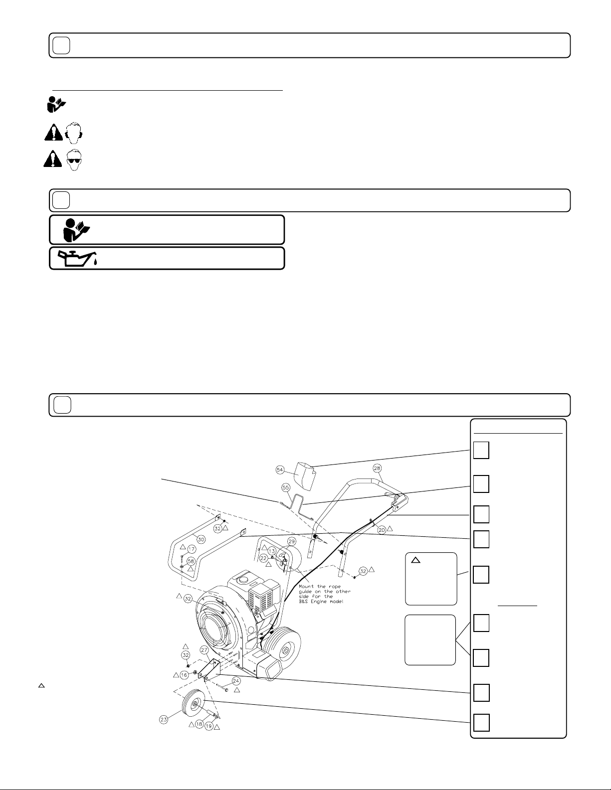
ASSEMBLY
Your Billy Goat is shipped from the factory in one carton,
completely assembled except for the upper handle assembly,
handle brace, plate deflector and throttle control.
These items should be included in your carton. If
any of these parts are missing, contact your dealer.
Boxing Chec klist
Denotes parts found in
Parts Bag Assembly
(shown on page 4).
Handle Upper
Assembly
400957
Check
Handle Brace
400951
·DO NOT place hands or feet inside air intake opening, near
exhaust outlet or near any moving parts.
·DO NOT start engine without deflector attached to exhaust outlet.
·DO NOT direct exhaust outlet toward any bystanders.
·DO NOT operate this equipment without first inspecting
work area.
·DO NOT operate this equipment during excessive vibration.
·DO NOT start engine without housing front plate attached.
·DO NOT operate this machine on slopes greater than 20%.
·DO NOT blow any hot or burning debris, or any toxic or
explosive material.
·DO NOT allow children to operate this equipment.
example). Finish installing the other side of the upper handle assembly using
screw (Item 17) and lock nut (Item 32).
2. Install front of handle brace (Item 30), to blower housing using
one screw (Item 17), one washer (Item 58) and one lock nut (item 32).
Install rear of handle brace (item 30) to upper handle vibration mounts using
two lock nuts (item 32). Hand tighten only.
3. Securely tighten all hardware listed above in steps 1 thru 2.
4. Remove four lock nuts from the front plate and use them to attach the front
wheel bracket (Item 27). Using spacer (Item 18), washer (Item 19), and Lock
Nut (Item 16) to attach Front wheel (Item 23) onto the front wheel bracket.
5.Connect spark plug wire.
Parts Bag &
Literature Assy
430334
Parts Bag
& Literature
Assy
Check
Per Model
Check
Engine
Manual
Per Model
Briggs & Stratton
10 HP
Honda 8 & 11 HP
Check
Check
Wire Loop
Front Exhaust
430336
Check
Front Exhaust
Director
430315
Check
Check
Bracket Front
Wheel 430270
Check
Front Wheel
430271
1.Install front exhaust wire loop(Item 55) across upper handle and
slide wire loop to lowest possible position on upper handle.
Install upper handle (Item 28), to preassembled lower handle
(item 29) by sliding the upper over and down the outside of the
lower handle. Pull recoil handle from the engine and place it
between rope guides (Item 13). Using screw (Item 22) & lock nut
(Item 32) to install upper handle to lower handle.
NOTE:
Install
rope guide on the left hand side for the Honda unit and right hand
side for the Briggs & Stratton unit (See fig below for the pictorial
NOTE:
Preassemble front
exhaust wire loop(Item 55)
across upper handle before
attaching upper handle to
lower handle.
Part No. 430316 Form No. F083100A
Page 4 of 12
These labels should be included on your Blower. If any of
these labels are damaged, replace them before putting this
equipment into operation. Item and part numbers are given to
help in ordering replacement labels.
4
Check
Owner's
Manual
430316
Check
Warranty
Card
400972
EU Declaration
of Conformity &
EU Distributor
List 430189
Literature Checklist
Owner's
Manual
Warranty
Card
EU Declaration
of Conformity
& EU
Distributor List
Throttle Control /
Gust Control
CONTROLS
PARTS BAG & LITERATURE ASSY P/N 430334
PARTS BAG ASSEMBLY CHECKLIST P/N 430340
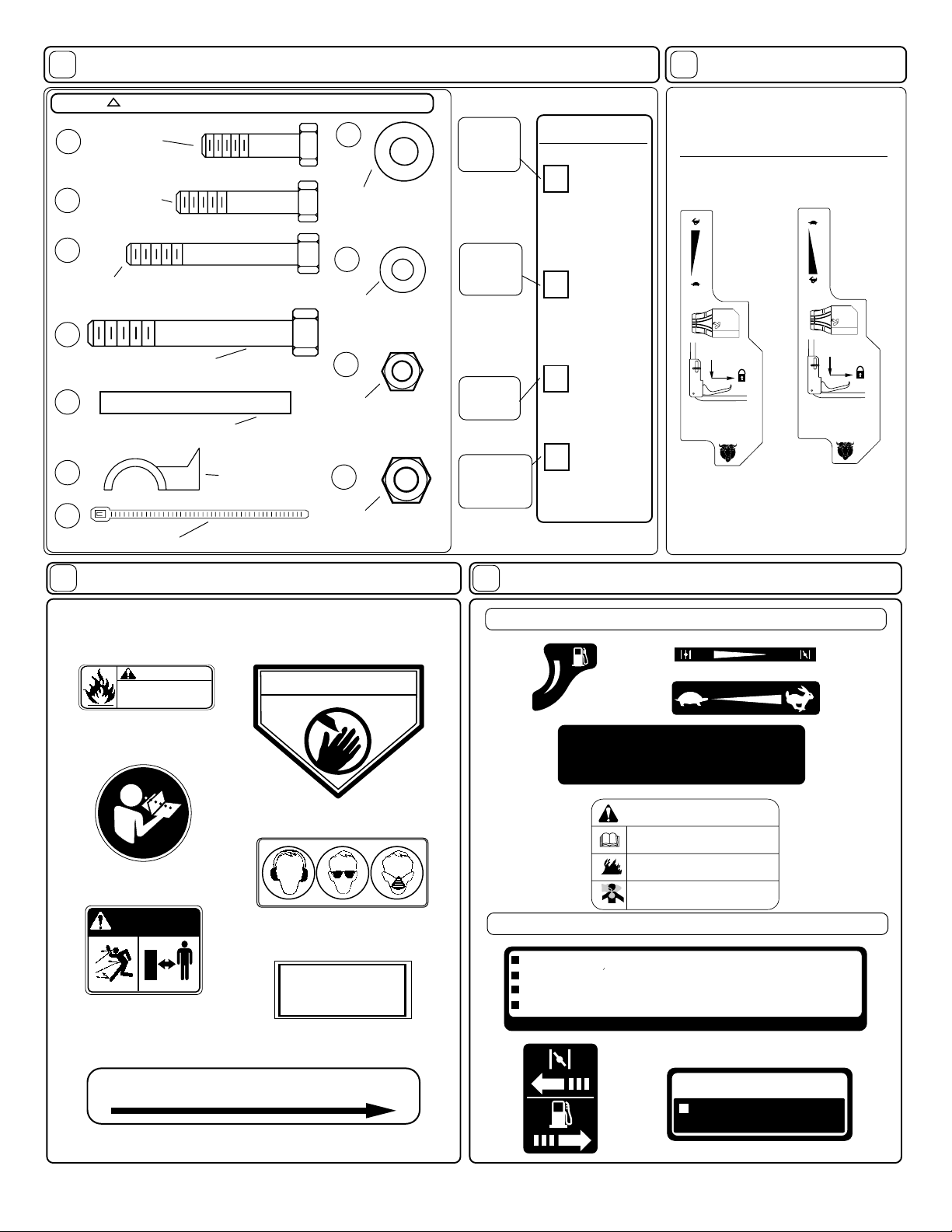
INSTRUCTION LABELS
ENGINE LABELS
12
15
13
WHEN OIL LEVEL LOW,
ENGINE STOPS IMMEDIATELY.
OIL ALERT
Honda
Briggs & Stratton
HONDA MOTOR CO. , LTD. MADE IN JAPAN
READ OWNER’S MANUAL BEFORE OPERATION.
LIRE LE MANUEL D UTILISATEUR AVANT USAGE.
VOR INBETRIEBNAHME UNBEDINGHT BEDIENUNGSANLEITUNG DURCHLESEN.
NO UTILIZAR SINANTES NO HABER LEIDO EL MANUAL
14
Label Do Not Fill While
Engine Is Hot
Item 11 Part No.400268
EXPLOSIVE FUEL
STOP ENGINE AND ALLOW TO
COOL BEFORE REFUELING.
400268
WARNING
Label Danger Keep Hands and Feet Aw a y
Item 41 Part No.400424
DANGER
DANGER
KEEP HANDS and FEET AWAY
KEEP HANDS and FEET AWAY
Label Read Owner's Manual
Item No. 59 Part No. 890301
DANGER
810736
Label Danger Flying Material
Item No. 44 Part No. 810736
890254
Label Ear Eye Breathing
Item No. 63 P art No. 890254
Literature
Parts Bag
430341
Check
Literature
Parts Bag
32
Nut Lock 5/16-18
8160002 Qty . 5
17
Screw Cap
5/16-18 x 1 3/4
8041031 Qty . 1
22
Screw Cap 5/16-18 x 2 1/2
8041034 Qty . 1
58
Washer 5/16 FLAT CUT
8171003 Qty . 1
Rope Guide
830533 Qty . 2
STOP
Part No:
430333
START
TO LOCK IN MIDDLE
SLIDE LEVER TO RIGHT TO LOCK
AIR DIRECTOR IN MIDDLE POSITION
TO UNLOCK
SQUEEZE THE LEVER TO UNLOCK
AIR DIRECTOR FROM MIDDLE
POSITION
1
2
STOP
Part No:
430351
START
TO LOCK IN MIDDLE
SLIDE LEVER TO RIGHT TO LOCK
AIR DIRECTOR IN MIDDLE POSITION
TO UNLOCK
SQUEEZE THE LEVER TO UNLOCK
AIR DIRECTOR FROM MIDDLE
POSITION
1
2
Honda
Briggs &
Stratton
PATENT
PENDING
PART NO. 500183
Label Patent No
Part No. 500183
RUN CHOKE
ON
OFF
THIS ENGINE EQUIPPED WITH
LOW OIL SENSOR, IF ENGINE WILL
NOT START, CHECK OIL LEVEL
WARNING
Read and follow Operating
Instructions before running engine.
Gasoline is flammable. Allow engine
to cool at least 2 minutes before fueling.
Engines emit carbon monoxide,
DO NOT run in enclosed area.
24
Screw Cap 3/8-16 x 3 3/4
8041061 Qty . 1
Cable T y 1"
900407 Qty . 3
20
19
Washer 1/2 SAE
8172011 Qty . 1
16
Nut Lock 3/8-16
8161042 Qty . 1
13
18
Spacer 1/2 OD x 3.062"
Qty . 1
Start Stop
PULL THEN SLIDE T O LOCK
Label Lever QB Item No. 46
Part No. 430363
14
Screw Cap
5/16-18 x 1 1/4
8041029 Qty. 1
Check
 Loading...