


MODEL P12
INTERNAL BLOWER
Page 1
For use with compatible Best range hoods. See hood manual for suitability.
WARNING 

TO REDUCE THE RISK OF FIRE, ELECTRIC SHOCK, OR INJURY TO PERSON(S) OBSERVE THE FOLLOWING:
1.Use this unit only in the manner intended by the manufacturer. If you have questions, contact the manufacturer at the address or telephone number listed in the warranty.
2.Before servicing or cleaning unit, switch power off at service panel and lock service disconnecting means to prevent power from being switched on accidentally.When the service disconnecting means cannot be locked, securely fasten a prominent warning device, such as a tag, to the service panel.
3.Installation work and electrical wiring must be done by qualified personnel in accordance with all applicable codes and standards, including fire-rated construction codes and standards.
4.Sufficient air is needed for proper combustion and exhausting of gases through the flue (chimney) of fuel burning equipment to prevent backdrafting.Follow the heating equipment manufacturer’s guidelines and safety standards such as those published by the National Fire Protection Association (NFPA), and the American Society for Heating, Refrigeration and Air Conditioning Engineers (ASHRAE), and the local code authorities.
5.When cutting or drilling into wall or ceiling, do not damage electrical wiring and other hidden utilities.
6.Ducted fans must always be vented to the outdoors.
7.Do not use this range hood with any additional solid-state speed control device.
8.To reduce the risk of fire, use only steel ductwork.
9.This unit must be grounded.
TO REDUCE THE RISK OF A RANGE TOP GREASE FIRE:
a)Never leave surface units unattended at high settings. Boilovers cause smoking and greasy spillovers that may ignite. Heat oils slowly on low or medium settings.
b)Always turn hood ON when cooking at high heat or when cooking flaming foods.
c)Clean ventilating fans frequently. Grease should not be allowed to accumulate on fan or filter.
d)Use proper pan size.Always use cookware appropriate for the size of the surface element.
WARNING 

TO REDUCE THE RISK OF INJURY TO PERSON(S) IN THE EVENT OF A RANGE TOP GREASE FIRE,OBSERVE THE FOLLOWING*:
1.SMOTHER FLAMES with a close-fitting lid, cookie sheet, or metal tray, then turn off the burner. BE CAREFUL TO PREVENT BURNS. IF THE FLAMES DO NOT GO OUT IMMEDIATELY, EVACUATE AND CALL THE FIRE DEPARTMENT.
2.NEVER PICK UP A FLAMING PAN – You may be burned.
3.DO NOT USE WATER, including wet dishcloths or towels – This could cause a violent steam explosion.
4.Use an extinguisher ONLY if:
A.You know you have a Class ABC extinguisher and you know how to operate it.
B.The fire is small and contained in the area where it started.
C.The fire department has been called.
D.You can fight the fire with your back to an exit.
* Based on “Kitchen Fire Safety Tips” published by NFPA.
CAUTION  !
!
1.For general ventilating use only. Do not use to exhaust hazardous or explosive materials and vapors.
2.To avoid motor bearing damage and noisy and/or unbalanced impellers, keep drywall spray, construction dust, etc. off power unit.
3.This blower has a thermal overload which will automatically shut off the motor if it becomes overheated.The motor will restart when it cools down.If the motor continues to shut off and restart, have the hood serviced.
4.Please read specification label on product for further information and requirements.
5.To reduce the risk of fire and to properly exhaust air on a ducted installation, be sure to duct air outside – Do not exhaust air into spaces within walls or ceiling or into attics, crawl spaces, or garage.
INSTALLER:
Save this manual for Electrical Inspector and Homeowner to use.

MODEL P12
Wall & Roof Caps,
Exterior Blowers
Elbows
Ductwork
In-Line
Damper
Blower
System
MODEL 437
(High capacity roof cap)
MODEL 418
(10” round adjustable elbow)
MODEL 410
(10” round duct—2 ft. sections)
MODEL 421
(10” round In-Line Damper - included)
OPTIONAL
DECORATIVE FLUE
OPTIONAL
FLAT TOP COVER ADPWP SERIES
(for WP29M Series
Hood Only)
Page 2
MODEL 441
(10’’ Round wall cap)
MODEL P12 BLOWER/ROUGH-IN KIT
(1200 cfm interior blower & rough-in plate)
NON-DUCT KIT FLUE
ANKWP SERIES
(for WP29M Series
Hood Only)
WP29M, IP29M, K260A SERIES HOOD
(Canopy with blower controls & lighting. Required for all installations.)
INTERNAL BLOWER RANGE HOOD SYSTEM
MODEL P12
INSTALLATION
VERTICAL DISCHARGE
MOUNTING |
MOUNTING |
|
STUDS |
||
STUDS |
||
|
||
|
COVER PLATE |
|
|
HEX |
|
|
NUTS |
|
|
ROUGH-IN |
|
|
PLATE |
HORIZONTAL DISCHARGE
COVER |
MOUNTING |
|
STUDS |
||
PLATE |
||
|
||
|
HEX |
|
|
NUTS |
MOUNTING
STUDS
ROUGH-IN
PLATE
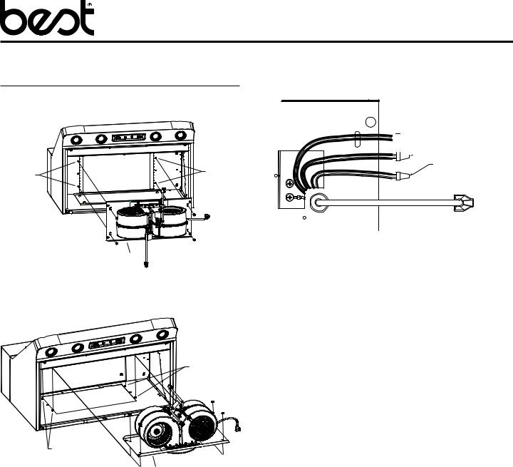
1.Attach ROUGH-IN PLATE to MOUNTING STUDS at inside, top of hood with (4) existing #10-32 HEX NUTS.
Page 3
ROUGH-IN PLATE


 BLACK TO BLACK

 WHITE TO WHITE
GREEN TO GREEN
OR BARE WIRE TO
GROUND SCREW
2.Remove wiring cover.
3.Run power cable to installation location, remove knockout from ROUGH-IN PLATE wiring box and connect cable to wiring box using proper connector. Connect BLACK TO BLACK (hot), WHITE TO WHITE (neutral) and GREEN OR BARE WIRE (ground) under second ground screw. Replace wiring cover.
4.Run 10” round steel duct to installation location.
5.Install 10” round damper (included) inside ductwork, at least 3” above mounting plate

MODEL P12
MOUNTING
PLATE
BLOWERS
HEX NUTS (8)
6.Connect duct to rough-in plate. Use duct tape to make all joints secure and air tight.
ROUGH-IN |
STUDS |
|
PLATE |
||
|
SLOTS
TABS |
Page 4
HOOD
 RECEPTACLE
ROUGH-IN 
 PLATE
PLATE
POWER
CORD

 HOOD
HOOD 
 RECEPTACLE
BLOWER |
POWER |
CORD |
BLOWER /
MOUNTING
PLATE
ASSEMBLY
HEX NUTS (2)
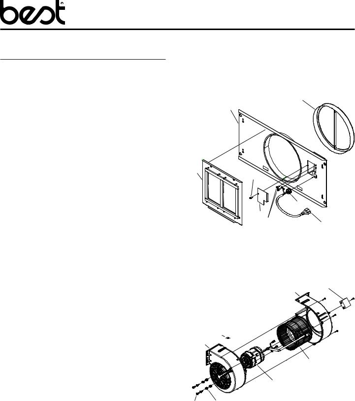
7.Attach BLOWERS to MOUNTING PLATE with (8) 10 -24 HEX NUTS.
8.Engage two TABS on BLOWER / MOUNTING PLATE ASSEMBLY into two SLOTS in ROUGH-IN PLATE. Secure blower / mounting plate assembly to THREADED STUDS on rough-in plate with (2) 10-24 HEX NUTS.
9.Plug BLOWER POWER CORD and ROUGH-IN PLATE POWER CORD into HOOD RECEPTACLES.
10.Wrap wires with wire tie (provided).
MODEL P12
SERVICE PARTS
Model P12
ROUGH IN PLATE
KEY |
PART |
DESCRIPTION |
QTY |
NO. |
NUMBER |
|
|
|
|
|
|
1 |
97018167 |
ROUGH-IN PLATE WELDMENT |
1 |
2 |
97018827 |
MOUNTING PLATE ASSEMBLY |
1 |
3 |
99440033 |
POWER CORD |
1 |
4 |
99150471 |
SCREW, #10-32 X 1/2 HEX |
|
|
|
WASHER HEAD* |
2 |
5 |
99400060 |
STRAIN RELIEF |
1 |
6 |
98003370 |
OUTLET BOX COVER |
1 |
7 |
99170245 |
SCREW, #8-18X3/8* |
1 |
8 |
99580015 |
10” DAMPER |
1 |
+ |
97018823 |
ROUGH-IN KIT (COMPLETE) |
|
|
|
|
|
+ NOT SHOWN
* STANDARD HARDWARE. MAY BE PURCHASED LOCALLY.
BLOWER
KEY |
PART |
DESCRIPTION |
QTY |
NO. |
NUMBER |
|
|
|
|
|
|
1 |
99111448 |
BLOWER HOUSING, MOTOR |
1 |
2 |
99111447 |
BLOWER HOUSING, INLET |
1 |
3 |
99271379 |
CAPACITOR |
1 |
4 |
99020298 |
BLOWER WHEEL |
1 |
5 |
99080629 |
MOTOR |
1 |
6 |
|
GROMMET (CONTAINED IN |
|
|
|
HARDWARE BAG) |
4 |
7 |
|
SCREW, M4 X 16.8MM |
4 |
8 |
|
SCREW, M4 X 0.7 X 16MM |
3 |
9 |
|
SCREW, M4 X 0.7 X 12MM |
1 |
10 |
|
RETAINING RING |
1 |
+ |
99770131 |
WIRE HARNESS |
1 |
+ |
97018828 |
HARDWARE BAG (CONTAINS |
|
|
|
KEY NUMBERS 6-10) |
1 |
+ |
97017924 |
BLOWER (COMPLETE) |
1 |
|
|
|
|
+ NOT SHOWN
Page 5
8
1
2 |
7 |
|
|
5 |
6 4 |
3 |
2 3
10 1 

4
5
7 6
 Loading...