


Bertazzoni REF36PRL, REF36PIXR, REF36PIXL, REF30PRR, REF36PRR User Manual
...REF30PIXL
REF30PIXR
REF30PRL
REF30PRR
REF36PIXL
REF36PIXR
REF36PRL
REF36PRR
INSTALLATION GUIDE |
EN |
NOTICE D’INSTALLATION |
FR |

IMPORTANT
Dimensions in parentheses are in inches: mm(in).
Weights in parentheses are in pounds: kg (lb).
Temperatures in parentheses are in Fahrenheit degrees: °C(°F)

Installation Guide
Index
|
Important Instructions |
Page 3 |
Important safety instructions |
|
Children safety |
Technical Requirements
4Appliance features and installation requirements
5Installation niche features: Integrated Series (BI)
6Installation niche requirements: Stainless Integrated Series (BKI)
Preparing To Install
7Transport to installation site and unpacking
8Electrical and Water connection
10 Levelling
Panels Mounting
11 Door and Bottom-Drawer overlay panels layout
13Overlay panels mounting brackets layout
14Panels Dimensions
15Mounting the handles on Integrated units
16Mounting panels to the door and the drawer of Integrated units
Installation
18Built-in installation of single appliance
19Built-in installation of two or more appliances
Completing The Installation
21Anti-tipping safety assembly
22Mounting handles on stainless front
23Air circulation
24Post installation checklist
25Start Up
English
Français
1

2
Installation Guide
Series: All
Important safely instruction
Symbols used in the Guide |
Note |
|
Tips for the correct use of the appliance |
||
|
Important
Directions to avoid appliance damage
Warning
Directions to prevent injury
Children safety
DANGER: Risk of child entrapment. Before you throw away your old refrigerator or freezer:
• Take off the doors
• Leave the shelves in place so that children may not easily climb inside.
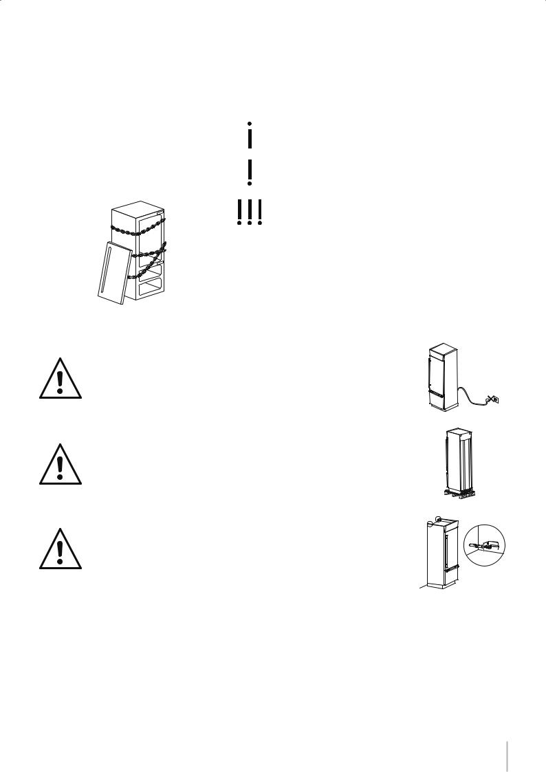
ATTENTION
This appliance must be transported in an upright position. If this was not the case you should leave it upright for 24 hours prior to switch it on.
24 h
English
Take maximum care during handling to avoid harm to persons and property.
Secure the top of the appliance to the wall with the two brackets provided with the appliance.
Français
3
Description |
StandPlus/ |
|
Integrated |
|
Classic |
|
X-pro |
|
|
||||
|
|
|
|
|
||
|
|
|
|
|
|
|
Appliance |
|
|
|
|
|
|
|
|
|
|
|
|
|
Fasteners, brackets, screws, wrench for mounting outer panels |
|
|
|
|
|
|
|
|
|
|
|
|
|
Alluminium trims to fill gap between appliance and cabinets |
|
|
|
|
|
|
|
|
|
|
|
|
|
Owner’s Kit (inside the appliance) |
|
|
|
|
|
|
|
|
|
|
|
|
|
|
|
|
|
|
|
|
|
|
|
Maker - Models |
Maker - Models |
||
Description |
|
|
|
without Ice |
||
|
|
with Ice Maker |
|
|||
|
|
|
|
Maker |
||
|
|
|
|
|
|
|
|
|
|
|
|
|
|
Water fill hose (only models with Ice Maker) |
|
|
|
|
|
|
|
|
|
|
|
|
|
Water filter (only models with Ice Maker) |
|
|
|
|
|
|
|
|
|
|
|
|
|
Leveling feet |
|
|
|
|
|
|
|
|
|
|
|
|
|
Anti-tipping brackets, fixing plugs and screws |
|
|
|
|
|
|
|
|
|
|
|
|
|
Appliance cleaning kit |
|
|
|
|
|
|
|
|
|
|
|
|
|
User Manual, Installation Guide, Guarantee Certificate |
|
|
|
|
|
|
|
|
|
|
|
|
|
Read the User Manual and the Guide attentively and keep it in a safe place.
Appliance features and installation requirements
Appliance dimensions
Integrated
Appliance dimensions
Stainless Integrated
Appliance dimensions with packaging
Weight with packaging
Voltage
Power supply cable
Potable water supply pressure
Water connection
Provided installation accessories
Additional equipment necessary
BI30 w: 749 mm (29 1/2”)/ h: 2120 mm (83 1/2”)/ d: 610 mm (24”) BI36 w: 899 mm (35 3/8”)/ h: 2120 mm (83 1/2”)/ d: 610 mm (24”)
BKI30 w: 749 mm (29 1/2”)/ h: 2120 mm (83 1/2”)/ d: 635 mm (25”) BKI36 w: 899 mm (35 3/8”)/ h: 2120 mm (83 1/2”)/ d: 635 mm (25”)
30” Series |
w: 800 mm (31 1/2”) / h: 2260 mm (89”) / d: 800 mm (31 1/2”) |
36” Series |
w: 950 mm (37 3/8”) / h: 2260 mm (89”) / d: 800 mm (31 1/2”) |
30” Series |
up to 275 kg (606 lb) |
36” Series |
up to 295 kg (650 lb) |
North America Version: 115V 60Hz
North America Version: 15 A
from 0.05 MPa to 0.5 MPa (0.5 Bar - 5 Bar)
3/4” female attachment
Customized panels mounting Kit
Anti-tipping Kit (B04000200)
 Lateral connecting kit (KCLIT/KCLIH)
4 mm (1/8”) allen wrench
Phillips head screwdriver
wood and percussion drill
2.5 mm (1/8”) bit for wood
 8 mm (3/8”) bit for walls
  17 mm (3/4”) wrench
Adjusting height of the rear rollers |
13 mm (1/2”) socket |
Note
Not all models come with an automatic ice maker. Verify if your model is equipped with an ice maker to determine if you require water supply.
4
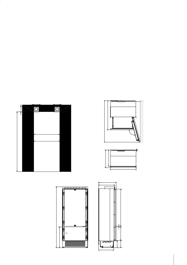
Aarea to be left clear for the anti-tipping brackets
Niche Height
2134 mm (84”)
Niche Width
BI36: 900 mm (35 1/2”) BI30: 750 mm (29 5/8”)
Door Swing Clearance
BI36: 1470 mm (57 7/8”) |
|
|
|
BI30: 1320 mm (52”) |
|
|
|
100 (4”) |
140 (5 ½”) |
140 (5 ½”) |
100 (4”) |
A |
A |
||
(84”) |
BI36: 900 (35 ½”) |
|
|
BI30: 750 (29 ⁄ ”) |
|
||
min 2134 |
|
||
|
|
|
|
2120 (83 ½”) +25 (1”) |
721 (28 ⁄”) +25 (1”) |
Installation Guide
Installation niche features: Integrated Series (BI)
Door Opening Angle
105°
Width
BI36: 899 mm (35 3/8”)
BI30: 749 mm (29 1/2”)
Height
2120 mm (83 1/2”) + 25 mm (1”)
Depth with door (without panel)
610 mm (24”) |
|
|
|
English |
⁄ ”)(571470BI36: (52”)1320BI30: (39”)992 |
BI36: 160 |
(6 |
⁄ ”) |
|
|
|
|||
|
BI30: 125 |
(5”) |
|
|
|
105° |
|
|
|
610 (24”) 560 (22”) |
10 (⁄”) |
|
|
Français |
BI36: 899 (35 ⁄”)
BI30: 749 (29 ½”)
610 (24”) |
560 (22”) |
|
|
|
1293 (50 ”⁄ ) |
|
|
|
20 (¾”) |
|
|
|
|
|
474 (18 ”⁄) |
|
500 (19 |
¾”) |
+25 (1”) |
+ 25 (1”) |
|
(9 ”⁄) (9¾”) |
|
|||
|
|
|
||
|
|
231 |
248 |
5 |
|
|
|
|
|
Series: All
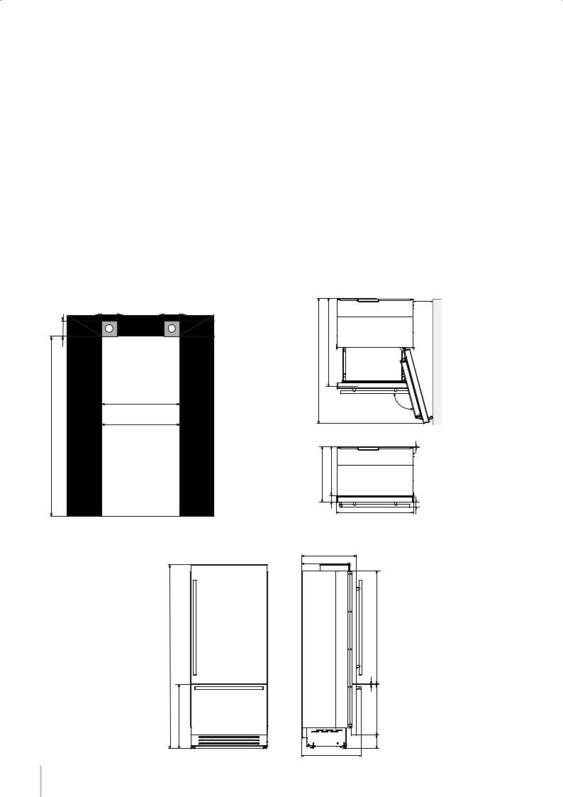
Installation niche requirements: Stainless Integrated Series (BKI)
Aarea to be left clear for the anti-tipping brackets
Niche Height
2134 mm (84”)
Niche Width
BKI36: 900 mm (35 1/2”) BKI30: 750 mm (29 5/8”)
Door Swing Clearance
|
BKI36: 1470 mm (57 7/8”) |
|
|
|
BKI30: 1320 mm (52”) |
|
|
100 (4”) |
140 (5 ½”) |
140 (5 ½”) |
100 (4”) |
A |
A |
||
(84”) |
BI36: 900 (35 ½”) |
|
|
BI30: 750 (29 ⁄ ”) |
|
||
min 2134 |
|
||
|
|
|
|
Door Opening Angle
105°
Width
BKI36: 899 mm (35 3/8”)
BKI30: 749 mm (29 1/2”)
Height
2120 mm (83 1/2”) + 25 mm (1”)
Depth with door (without panel)
635 mm (25”) |
|
|
|
BKI36: 230 |
(9”) |
|
BKI30: 195 |
(7 ¾”) |
BKI36: 1470 (57 ⁄ ”) BKI30: 1320 (52”) |
|
|
|
105° |
|
(25”) (22”) |
10 (⁄”) |
|
635 560 |
|
|
75(3”) |
BKI36: 899 |
(35 |
⁄ ”) |
(2¼”) |
|
|
|||
|
BKI30: 749 |
(29 ½”) |
58 |
|
|
|
|
|
|
635 (25”) |
560 (22”) |
½”) +25 (1”) |
1308 (51 ½”) |
2120 (83 |
9 ( ⁄”) |
732 (28 ”⁄)+25 (1”) |
587 (23 ⁄”) |
146(5 ¾”) + 25(1”) |
|
693 (27 ¼”) |
|
6
Installation Guide
Series: All
Preparing the installation
Transport to installation site Since this is a large and heavy appliance, before transporting the ap- and unpacking pliance, check the access to the location where it will be installed
(door size, manoeuvring space in stairwells, etc.).
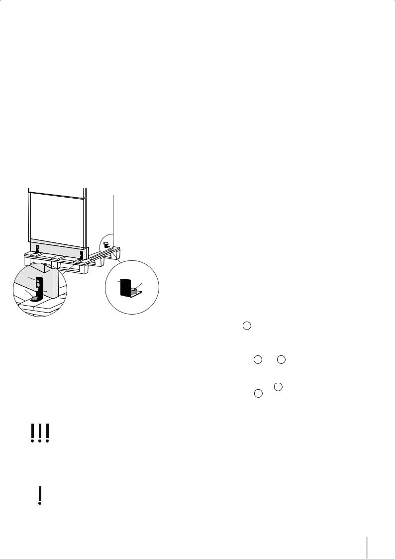
The appliance is attached to the base of the packaging (pallet) through four bolts which can be removed using a 17 mm (3/4”) wrench. It is recommended to use a manual transporting device to move the appliance to the installation site, and only at this point to remove the base of the packaging.
The appliance should always be transported in an erect position.
If this is not possible, transport the appliance laying on its rear side.
Once at the installation site, the appliance, which is equipped with four wheels, can be taken off the pallet and positioned in the installation area.
English
2 |
4 |
1 |
|
1 |
|||
3 |
|
The appliance is very heavy.
Take maximum care during handling to avoid injury.
The appliance should always be transported in an erect position.
Avoid at all costs leaning it on its front side.
Operate as follows:
 Take off the four bolts 1 securing the appliance to the pallet by means of a 17 mm (3/4”) wrench or socket.
 Remove the fixing brackets 3 and 4 .
 To remove the front fixing bracket 3 , unscrew for one or two turns the rear wheel adjusting bolt 2 by means of a 13 mm (1/2”) socket, do not overtighten the nut as it could damage the leveling feet adjusting system.
 From the back of the unit and by means of a suitable, high duty hand trolley, take off the appliance and place it on the floor. Be mindful of any debris on the floor which could get caught under the rollers and potentially damage the flooring when moving the appliance.
Be very careful to avoid any damage to floors. Delicate floors should be protected with plywood, hard cardboard or similar material panels.
Français
7
Series: All
Electrical and Water connection
E |
W |
W E
E |
W |
The appliances are delivered from the factory for operation at 110V120V AC - 60Hz (US and Canada).
Do not connect the refrigerator to any GFCI receptacle.
They are provided with a suitable supply cable and plug to be connected to an appropriate 15A socket (US and Canada) provided with an effective grounding.
A circuit breaker should also be installed and should be easily accessible so that it can be easily switched off before performing any installation or maintenance.
To connect to the water supply system (for appliances equipped with ice makers) a 1/4” waterline with accessible shut-off valve must be supplied.
The appliance is provided with a water adapter elbow which is suitable for high water pressure and complies the Food Regulations.
The water filter cartridge, which is provided with the appliance, should be installed according to the accompanying instructions. Use only the new adapter which is supplied with the appliance. The solenoid connection on the appliance is 3/4” diameter but is metric threaded. A standard garden hose threaded connector such as a braided stainless hose found at typical hardware stores will strip or damage the solenoid threads. Use only the supplied 1/4” quick connect elbow adapter for connecting a 1/4” copper or polyethylene source water line to the appliance.
Electrical cord length: 2500 mm (98 3/8”)
Water connection line length: 2500 mm (98 3/8”)
Do not use extension cords and/or multiple adapters for the power supply connection.
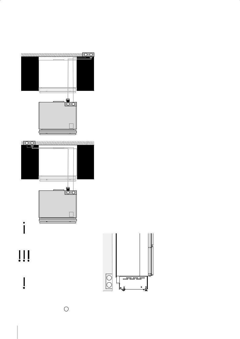
W E
Electrical and water supply behind the unit
Integrated Series
The Built-in filter cannot make it safe to drink any water which is not suitable for human consumption.
The appliance should be connected only to a drinkable water supply system.
E
W
Do not use extension cords or adapters.
Once the appliance is fully installed, connected to the water supply (if applicable) and operational, in the event that the water supply must be turned off,(touch the button  on control panel to switch it off) before the main water is shut off to prevent the appliance from entering a ‘NO WATER IN’ alarm state.
8
Installation Guide
Series: All
Back of appliance
Electrical connection
Water connection
English
Operate as follows:
Unwind the electric cable and connect it directly to the wall socket.
 Make sure the appliance is in the Stand-by condition and that all lights are off; should it be not so press the Unit button
  to switch it off.
 Push the 1/4” source waterline fully into the elbow connector then thread the elbow adapter to the solenoid at the back of the appliance.
Firmly tighten with fingers - a tool / wrench should not be needed to make a proper seal. Turn on the water and ensure all connections are not leaking prior to pushing the unit into the niche.
Français
9
Series: All
Levelling
2
2
1
1
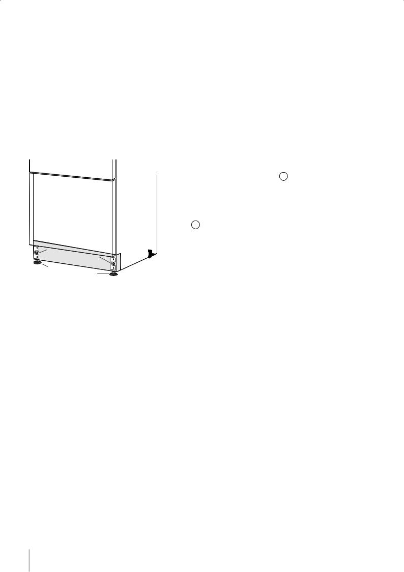
Adjust the appliance level by means of the front levelling feet and the rear adjustable wheels.
Operate as follows:
 The grille should ship taped to the back of the appliance. If by chance it is already in place, remove the grille (it is kept in position by magnets), adjust the height of the levelling feet 1 by means of a 17
mm (3/4”) wrench.
 Then adjust the height of the rear wheels by turning the front adjusting bolts 2 clockwise or counter-clockwise as it may be required. (Do not use power drivers with high torque settings for this step as it could damage the levelling mechanism)
 Mount the lower ventilation grille only after the unit is finally levelled in the niche.
10
1
2
3
Installation Guide
Series: Integrated (BI)
Door and Bottom-Drawer overlay panels layout
The dimensions of the panels are indicated in the table and drawings on pages 13.
Nevertheless, according to the requirements for aligning with other kitchen structures, the door panel can be higher than the upper edge of the refrigerator door, and the drawer panel can be lower than the edge of the drawer.
The panels must be mounted using special braces which attach |
|
|||
to adjustable devices provided on the door and drawer and with |
|
|||
brackets that anchor and adjust the panel’s vertical direction. |
|
English |
||
and must be applied to the panel as indicated. |
|
|||
Braces, brackets and fixing screws are provided with the appliance |
|
|||
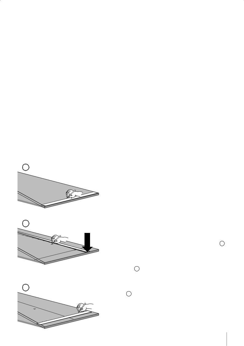
Operate as follows: |
|
Français |
||
To prepare the panels to be mounted on the appliance, follow |
||||
|
||||
these steps, working on the back of the panel. |
|
|
||
Door Panel |
|
|
||
|
Draw a reference center line, dividing the panel width in half |
1 . |
|
|
|
|
|||
|
|
|||
 Starting from the bottom edge of the panel, mark the positioning of the brackets 2 .
 Following the corresponding table, mark the outside and then the inside hole 3 .
11

Series: Integrated (BI)
4
 Position the brackets on each set of marks to make sure they are aligned 4 , you may wish to drill pilot holes (pay close attention to the panel’s thickness) 5 .
Screw the brackets in place 6 .
5
Drawer Panel
 When preparing the Drawer Panel, follow the same instructions as per the door panel, but make sure measurements are taken starting from the top edge 7 . The support bracket faces the opposite way 8 (note imgs 4 and 8).
7
8
12

Installation Guide
Series: Integrated
Overlay panels mounting brackets layout
|
Series 36 |
Series 30 |
A |
897 (35 ¼”) |
747 (29 ⁄ ”) |
|
|
|
B |
417 (16 ⁄ ”) |
342 (13 ½”) |
|
|
|
C |
354.5 (14”) |
279.5 (11”) |
|
|
|
English
Holes positions
Note: All lateral bracket placement measurements go from the center line to the outside bracket hole
Vertical adjustment bracket for upper door. Note orientation.
Vertical adjustment bracket for lower drawer. Note orientation.
|
|
|
|
A |
|
|
|
|
|
B |
|
B |
|
|
|
|
6,5 (¼”) |
6,5 (¼”) |
|
|
|
|
|
|
|
|
Door panel |
|
|
|
34 (1 ⁄ ”) |
|
|
Français |
1273 (50 ⁄ ”) |
1163 (45 ¾”) |
|
Back of the panel |
|||
660 (26”) |
(6 ¼”) |
|
min1390(54¾”) |
|||
|
|
|
157 |
|
|
|
|
|
|
A |
|
|
|
(4”) |
B |
B |
|
|
|
Drawer panel |
|
|
(15 ”⁄) |
100 |
|
|
(20”) |
Back of the panel |
|||
34 (1 ⁄ ”) |
(25”) |
|||
507.5 |
382 |
|
max 635 |
|
|
13 (½”) |
|||
|
|
|
|
|
|
|
|
C |
C |
13
Series: Integrated (BI)
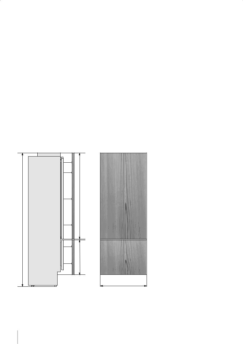
Panels Dimensions
Panels can have thickness ranging between 18 mm (3/4”) and 28 mm (1-1/8“).
Door panels can have a maximum weight 23 kg (51 lbs) and drawer panels may be a maximum weight of 11kg (25 lbs) Exceeding these weights could void your warranty for any service issues which can be attributed to overweight panels.
The hinging mechanism on appliances is considered to be `Zero-clearance`. The door and drawer widths specified below assume the minimum niche width is being used and a 3.5mm (1/8”) reveal is desired around the panels. Adjust your panel dimensions accordingly to your own design criteria considering your niche width and your reveal. Minimum reveal / gap should not be less than 1.5mm (1/16”).
Series |
Door/Drawer Width |
Niche Width |
|
|
|
BI36 |
897 (35 1/4”) |
900 (35 1/2”) |
|
|
|
BI30 |
747 (29 3/8”) |
750 (29 5/8”) |
|
|
|
2121 (83 ½") + 25 (1")
1390 (54 ¾”)
3 (⁄ ”)
min 540 (21 ¼”) max 635 (25”)
Example:
84” niche height 36” niche width 4” toe kick height
1/8” gap desired all around
Door panel:
Width: 35-3/4”
Height: 54-3/4”
Drawer panel:
Width: 35-3/4”
Height: 84”-1/8”-54-3/4”-1/8”-4”=25”
If you want a 6” toe kick height then your bottom drawer panel height would be 23”
A
14
1
2
Installation Guide
Series: Integrated (BI)
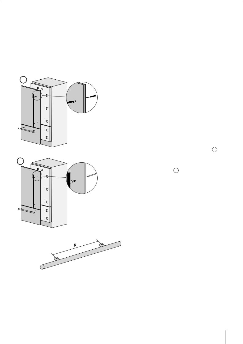
Mounting the handles on Integrated units
Handles will have to be mounted on the panels before they are applied to the fridge. For overlay panel mounting, remove the screw connecting the stand-offs to the handle bar. The overlay screw will pass through the overlay panel, the stand-off and into the handle bar.
Operate as follows:
|
Drill two holes of 5 mm (1/4 “) on the rear side panels, |
in- |
English |
|
|
|
|||
sert the supplied screws to the distance indicated |
in |
the |
|
|
the table below. To center the vertical handle (code |
HV) |
to |
|
|
the center of the door, split into two the height of the panel and make |
|
|||
a hole at -450 mm (-17 3/4”) and one at +450 mm (+17 3/4”) |
1 . |
|
|
|
 Place the handle on top of the holes and insert the screws through the panel and into the handle support 2 .
Français
Distance between stand-offs X |
900 mm |
480 mm |
490 mm |
|
(35 1/2”) |
(18 7/8”) |
(19 1/4”) |
||
|
||||
|
|
|
|
15
 Loading...