


Bertazzoni KMC36NE, KMC30X, KMC30NE, KMC36BI, KMC48BI User Manual
...Installation Instructions Use and Care Information
Instructions d'installation Utilisez et d'entretien
KMC30X KMC36X KMC48X KMC30BI KMC36BI KMC48BI KMC30NE KMC48NE KMC36NE
READ AND SAVE THESE INSTRUCTIONS BEFORE YOU START
INSTALLING THIS RANGEHOOD
WARNING: - TO REDUCE THE RISK OF A RANGE TOP GREASE FIRE:
a)Never leave surface units unattended at high settings. Boilovers cause smoking and greasy spillovers that may ignite. Heat oils slowly on low or medium setting.
b)Always turn hood ON when cooking at high heat or when flambeing food (i.e. Crepes
Suzette, Cherries Jubilee, Peppercorn Beef Flambé).
c)Clean ventilating fans frequently. Grease should not be allowed to accumulate on fan or filter.
d)Useproperpansize. Alwaysusecookwareappropriateforthesizeofthesurfaceelement.
WARNING: - TO REDUCE THE RISK OF INJURY TO PERSONS IN THE EVENT OF A RANGE TOP GREASE FIRE, OBSERVE THE FOLLOWING*:
a)SMOTHERFLAMESwithaclose-fittinglid,cookiesheet,ormetaltray,thenturnofftheburner. BE CAREFUL TO PREVENT BURNS. If the flames do not go out immediately EVACUATE
AND CALL THE FIRE DEPARTMENT.
b)NEVER PICK UP A FLAMING PAN - You may be burned.
c)DO NOT USE WATER, including wet dishcloths or towels - a violent steam explosion will result.
d)Use an extinguisher ONLY if:
1.You know you have a Class ABC extinguisher, and you already know how to operate it.
2.Thefireissmallandcontainedintheareawhereitstarted.
3.Thefiredepartmentisbeingcalled.
4.Youcanfightthefirewithyourbacktoanexit.
* Based on "Kitchen Firesafety Tips" published by NFPA
WARNING - TO REDUCE THE RISK OF FIRE OR ELECTRIC SHOCK, do not use this fan with any solid-state speed control device.
WARNING - TO REDUCE THE RISK OF FIRE, ELECTRICAL SHOCK, OR INJURY TO PERSONS, OBSERVE THE FOLLOWING:
1.Use this unit only in the manner intended by the manufacturer. If you have any questions, contact the manufacturer.
2.Before servicing or cleaning unit, switch power off at service panel and lock the service disconnecting means to prevent power from being switched on accidentally. When the service disconnecting means cannot be locked, securely fasten a prominent warning device, such as a tag, to the service panel.
CAUTION: For General Ventilating Use Only. Do Not Use To Exhaust Hazardous or Explosive Materials and Vapors.
WARNING - TO REDUCE THE RISK OF FIRE, ELECTRICAL SHOCK, OR INJURY TO PERSONS, OBSERVE THE FOLLOWING:
1.InstallationWorkAndElectricalWiringMustBeDoneByQualifiedPerson(s)InAccordance With All Applicable Codes And Standards, Including Fire-Rated Construction.
2.Sufficient air is needed for proper combustion and exhausting of gases through the flue (chimney) of fuel burning equipment to prevent backdrafting. Follow the heating equipment manufacturer's guideline and safety standards such as those published by the National Fire Protection Association (NFPA), and the American Society for Heating, Refrigeration and Air Conditioning Engineers (ASHRAE), and the local code authorities.
2
3.When cutting or drilling into wall or ceiling, do not damage electrical wiring and other hidden utilities.
4.Ducted fans must always be vented to the outdoors.
ALL WALL AND FLOOR OPENINGS WHERE THE RANGEHOOD
IS INSTALLED MUST BE SEALED.
Thisrangehoodrequiresatleast24"ofclearance between the bottom of the rangehood and the cooking surface or countertop. This hood has been approved by UL at this distance from the cooktop. This minimum clearance may be higher depending on local building codes. For gas cooktops and combination ranges, a minimum of 30" is recommended and may be required.
Overhead cabinets on both sides of this unit must be a minimum of 18" above the cooking surface or countertop. Consult the cooktop or range installation instructions given by the manufacturer before making any cutouts.
MOBILE HOME INSTALLATION The installation of this rangehood must conform to the Manufactured Home Construction and Safety Standards, Title 24 CFR, Part 3280 (formerly Federal Standard for Mobile Home Construction and Safety, Title 24, HUD, Part 280). See Electrical Requirements.
VENTING REQUIREMENTS
Determine which venting method is best for your application. Ductwork can extend either through the wall or the roof.
Thelengthoftheductworkandthenumberofelbowsshouldbekepttoaminimumtoprovideefficient performance. The size of the ductwork should be uniform. Do not install two elbows together. Use duct tape to seal all joints in the ductwork system. Use caulking to seal exterior wall or floor opening around the cap.
Flexible ductwork is not recommended. Flexible ductwork creates back pressure and air turbulence that greatly reduces performance.
Make sure there is proper clearance within the wall or floor for exhaust duct before making cutouts.
Do not cut a joist or stud unless absolutely necessary. If a joist or stud must be cut, then a supporting frame must be constructed.
WARNING - To Reduce The Risk Of Fire, Use Only Metal Ductwork.
CAUTION-Toreduceriskoffireandtoproperlyexhaustair,besuretoductairoutside–Do notventexhaustairintospaceswithinwallsorceilingsorintoattics,crawlspaces,orgarages.
Cold Weather installations
An additional back draft damper should be installed to minimize backward cold air flow and a nonmetallic thermal break should be installed to minimize conduction of outside temperatures as part of the vent system. The damper should be on the cold air side of the thermal break. The break should be as close as possible to where the vent system enters the heated portion of the house.
WARNING
•Venting system MUST terminate outside the home.
•DO NOT terminate the ductwork in an attic or other enclosed space.
•DO NOT use 4" laundry-type wall caps.
•Flexible-type ductwork is not recommended.
•DO NOT obstruct the flow of combustion and ventilation air.
•Failure to follow venting requirements may result in a fire.
3
ELECTRICAL REQUIREMENTS
A 120 volt, 60 Hz AC-only electrical supply is required on a separate 15 amp fused circuit. A time-delay fuse or circuit breaker is recommended. The fuse must be sized per local codes in accordancewiththeelectricalratingofthisunitasspecifiedontheserial/ratingplatelocatedinside the unit near the field wiring compartment.
WARNING
•Electrical ground is required on this rangehood.
•If cold water pipe is interrupted by plastic, nonmetallic gaskets or other materials, DO NOT use for grounding.
•DO NOT ground to a gas pipe.
•DO NOT have a fuse in the neutral or grounding circuit. A fuse in the neutral or grounding circuit could result in electrical shock.
•Check with a qualified electrician if you are in doubt as to whether the rangehood is properly grounded.
•Failure to follow electrical requirements may result in a fire.
State of California Proposition 65 Warning (US only)
 WARNING
This product contains chemicals known to the State of California to cause cancer and birth defects or other reproductive harm.
For more information go to www.P65Warnings.ca.gov
4
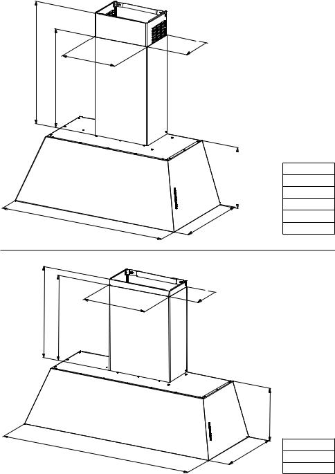
RANGEHOOD DIMENSIONS
MIN AS 21-7/8''- MAX ASP 36'' MIN REC 25-3/8''- MAX REC 39-15/16'' 20-1/2 ''
11-13/16''
29-7/8'' |
- |
35-13/16'' |
|
|
-7/8''  7
7
12-5/8''
-1/16'' 18
KMC30X
KMC30BI
KMC30NE
KMC36X
KMC36BI
KMC36NE
21-7/8''-MAX 39-15/16'' |
20-1/2'' |
MIN |
|
47-7/8''
15-3/4''
-7/8''  7
7
12-5/8''
'' |
KMC48X |
|
-1/16 |
KMC48BI |
|
18 |
||
|
||
|
KMC48NE |
5
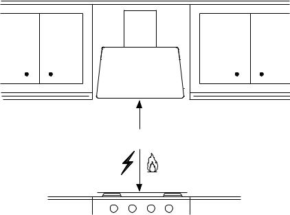
Min. 24" Min. 30"
6
MAIN PARTS
KMC30X - KMC30BI - KMC30NE
12e |
|
|
12d |
12b |
12a |
|
12f |
|
|
|
|
|
|
|
|
7.2.1 |
|
|
10 |
|
|
|
2.1 |
|
|
|
10e |
|
|
|
|
|
|
|
2.2 |
|
8 |
|
|
3 |
|
|
|
|
|
|
|
|
9.2 |
9.1 |
9.3 |
|
1 |
|
|
|
|||
|
|
|
|
|
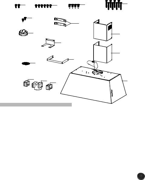
Components
Ref. Qty. Product Components
11 Hood Body, complete with:
Controls, Light, Filters, Blower.
21 Telescopic Chimney comprising:
2.11 Upper Section
2.21 Lower Section
3 |
1 |
Angle bracket |
|
|
10 |
1 |
Damper ø 5 7/8" |
|
|
10e |
1 |
Support connection for recirculating |
|
|
9 |
1 |
Connection |
|
|
|
|
for recirculating comprising: |
|
|
9.1 |
1 |
Connection for recirculating |
|
|
|
Parts needed |
|||
9.2 |
1 |
Spacer connection for recirculating |
|
|
9.3 |
1 |
Spacer connection for recirculating |
|
- 6" Round Metal ductwork. |
8 |
1 |
Recirculation Vent Grill |
|
|
Ref. |
Qty. |
Installation Components |
|
|
7.2.1 |
2 |
Upper Chimney Section |
|
Available Accessories |
|
|
Fixing Brackets |
|
- Recirculation Vent Kit - Activated |
12a |
8 |
Screws 3/16" x 1 15/16" |
|
|
12b |
4 |
Screws 1/8" x 3/8" |
|
Charcoal Filter - sku# FILTER1 |
12d |
6 |
Screws 1/8" x 1/4" |
|
- Washable Long Lasting Charcoal Filter |
12e |
2 |
Screws 1/8" x 3/8" |
|
Kit - sku# FILTER1LL |
12f |
2 |
Screws 1/8" x 1/2" |
|
- Wireless Remote Control Accessory - |
|
Qty. |
Documentation |
|
REMCTRL2 |
|
1 |
Instruction Manual |
|
|
|
|
|
||
|
|
|
7
MAIN PARTS
KMC36X - KMC36BI - KMC36NE
12e |
|
|
12d |
12b |
12a |
|
|
12f |
|
7.2.1 |
|
|
|
|
|
|
|
|
10 |
|
|
|
2.1 |
|
|
|
|
|
|
|
|
|
10e |
|
|
|
|
|
|
|
2.2 |
|
|
|
|
3 |
|
|
8 |
|
|
|
|
|
9.2 |
9.1 |
9.3 |
|
1 |
|
|
|
|||
|
|
|
|
|
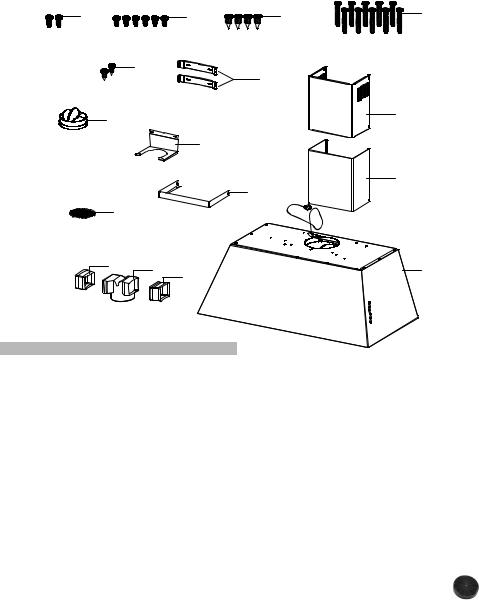
Components
Ref. Qty. Product Components
11 Hood Body, complete with:
Controls, Light, Filters, Blower.
21 Telescopic Chimney comprising:
2.11 Upper Section
2.21 Lower Section
3 |
1 |
Angle bracket |
|
|
10 |
1 |
Damper ø 5 7/8" |
|
|
10e |
1 |
Support connection for recirculating |
|
|
9 |
1 |
Connection |
|
|
|
|
for recirculating comprising: |
|
|
9.1 |
1 |
Connection for recirculating |
|
|
|
Parts needed |
|||
9.2 |
1 |
Spacer connection for recirculating |
|
|
9.3 |
1 |
Spacer connection for recirculating |
|
- 6" Round Metal ductwork. |
8 |
1 |
Recirculation Vent Grill |
|
|
|
|
|||
Ref. |
Qty. |
Installation Components |
|
|
|
|
|||
7.2.1 |
2 |
Upper Chimney Section |
|
|
|
Available Accessories |
|||
|
|
Fixing Brackets |
|
|
|
|
|
|
|
12a |
10 |
Screws 3/16" x 1 15/16" |
|
- Recirculation Vent Kit - Activated |
12b |
4 |
Screws 1/8" x 3/8" |
|
Charcoal Filter - sku# FILTER1 |
12d |
6 |
Screws 1/8" x 1/4" |
|
- Washable Long Lasting Charcoal Filter |
12e |
2 |
Screws 1/8" x 3/8" |
|
|
|
Kit - sku# FILTER1LL |
|||
12f |
2 |
Screws 1/8" x 1/2" |
|
|
|
- Wireless Remote Control Accessory - |
|||
|
Qty. |
Documentation |
|
|
|
|
REMCTRL2 |
||
|
1 |
Instruction Manual |
|
|
|
|
|
8
MAIN PARTS
KMC48X - KMC48BI - KMC48NE
12e |
12d |
12b |
12a |
|
|
7.2.1 |
|
|
10 |
|
2.1 |
8
2.2
3
1
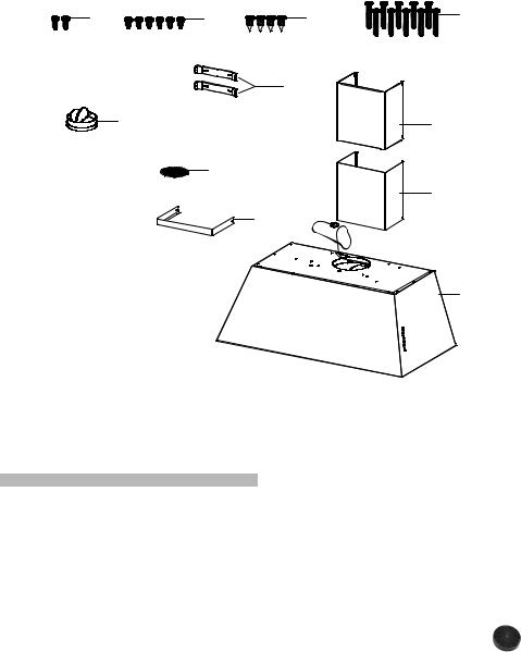
Components
Ref. Qty. Product Components
11 Hood Body, complete with:
Controls, Light, Filters, Blower.
21 Telescopic Chimney comprising:
2.1 |
1 |
Upper Section |
|
|
|
|
Parts needed |
||||
2.2 |
1 |
Lower Section |
|
||
3 |
1 |
Angle bracket. |
|
- 6" Round Metal ductwork. |
|
10 |
1 |
Damper ø 5 7/8" |
|
|
|
8 |
1 |
Recirculation Vent Grill |
|
|
|
|
|
|
|
Available Accessories |
|
Ref. |
Qty. |
Installation Components |
|||
7.2.1 |
2 |
Upper Chimney Section Fixing |
|||
|
- Recirculation Vent Kit - Activated |
||||
|
|
Brackets |
|
||
12a |
10 |
Screws 3/16" x 1 15/16" |
|
Charcoal Filter - sku# FILTER1 |
|
12b |
4 |
Screws 1/8" x 3/8" |
|
- Washable Long Lasting Charcoal Filter |
|
12d |
6 |
Screws 1/8" x 1/4" |
|
Kit - sku# FILTER1LL |
|
12e |
2 |
Screws 1/8" x 3/8" |
|
- Wireless Remote Control Accessory - |
|
|
Qty. |
Documentation |
|
REMCTRL2 |
|
|
1 |
Instruction Manual |
|
||
|
|
|
9
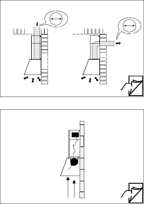
|
Choose your ducting method |
|
INSTALLATION WITH THE CHIMNEY |
|
Ducted Venting Installation |
Vertical |
6" |
|
6" |
Horizontal
 12
12
Non Ducted - Recirculation Option
Requires purchase of
Activated
Charcoal Accessory.
 19
19
10
Choose your ducting method
INSTALLATION WITHOUT THE CHIMNEY
Non Ducted - Recirculation Option |
Ducted Venting Options Installation |
6"

 Rear
Rear
Requires purchase of Activated Charcoal Accessory
When used in recirculation mode, To Reduce the Risk of Fire and Shock use only conversion kit Model FILTER1 or FILTER1LL.
22 |
26 |
11
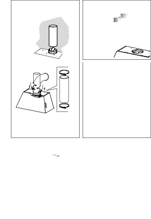
Only for Ducted Venting Installation
Install Damper that is included with the Hood before connecting to the ductwork.
Installation Instructions
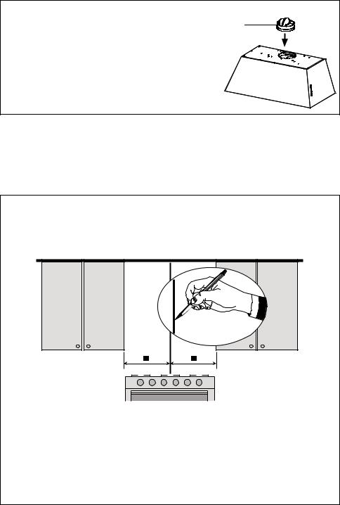
1
Draw a vertical line on the supporting wall as high as practical, at the center of the area in which the hood will be installed.
Draw a horizontal line at where the bottom edge of the hood will be located as indicated in the figure that is a minimum of 24" above Electric cooking surface and 30" above Gas.
12
2.a |
|
|
|
KMC30X |
|
|
KMC30BI |
|
|
KMC30NE |
|
|
30" |
|
>1 1/8” |
|
|
|
|
|
|
|
|
|
|
|
5 |
6 |
|
|
|
|
|
2.1 |
|
2.1 |
7.2.1 |
|
|
|
|
|
|
|||
|
7 |
8 |
|
|
|
|
|
|
|
|
7 |
8 |
|
|
|
|
|
5 |
6 |
|
|
|
|
|
3 |
4 |
|
|
9 1/16" |
9 |
1/16" |
1 |
2 |
x8 |
|
|
|
||||
|
6 1/2" |
6 1/2" |
|
|
|
|
|
|
|
|
|
7 |
8 |
|
|
|
|
|
5 |
6 |
|
1 |
|
2 |
|
3 |
4 |
|
|
|
1 |
2 |
||
|
|
|
|
|
||
10 7/16" |
|
|
|
|
Ø 5/16” |
x8 |
3 |
3 |
|
4 |
|
|
|
15/16" |
|
|
|
|
|
|
|
Min. |
|
|
Min. |
|
|
|
24" |
|
|
30" |
|
|
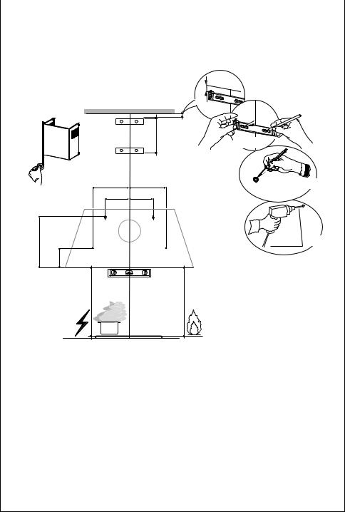
Mark the wall where indicated, 10 7/16" above the horizontal line and at 6 1/2" distance on the left and right of vertical line. Checking that the two marks are level.
Insert two wall plugs and two screws into the holes as shown not completely (purchased separately). Mark the wall where indicated, 3 15/16" above the horizontal line and at 9 1/16" distance on the left and right of vertical line. Checking that the two marks are level.
Insert two wall plugs (purchased separately).
Place a bracket 7.2.1 on the wall as shown about 1 1/8" from the ceiling or upper limit, aligning the center (notch) with the vertical reference line and mark the wall at the centers of the holes in the bracket.
Place the second bracket 7.2.1 on the wall as shown, below the first bracket, at the height of the upper chimney section supplied and aligning the center (notch) with the vertical line.
Mark the wall at the centers of the holes in the bracket and drill ø 5/16" as shown.
Installation screws provided for the Brackets, must be secured with wall plugs (purchased separately).
13
2.b
|
36" |
>1 1/8” |
|
|
|
|
|
|
|
|
9 |
10 |
|
|
|
2.1 |
2.1 |
7.2.1 |
|
|
|
|||
|
7 |
8 |
|
|
|
13 12/16" |
13 12/16" |
9 |
10 |
|
7 |
8 |
||
|
|
|
5 |
6 |
|
12 3/16" |
12 3/16" |
3 |
4 |
|
1 |
2 |
||
|
6 1/2" |
6 1/2" |
|
|
|
5 |
6 |
|
|
|
1 |
2 |
|
|
11" |
10 7/16" |
|
|
|
|
3 |
|
4 |
|
|
3 15/16" |
|
|
|
|
Min. |
|
Min. |
|
|
24" |
|
30" |
|
KMC36X
KMC36BI
KMC36NE
|
|
x10 |
|
|
9 |
10 |
|
|
7 |
8 |
|
|
5 |
6 |
|
|
3 |
4 |
|
Ø 5/16” |
1 |
2 |
x10 |
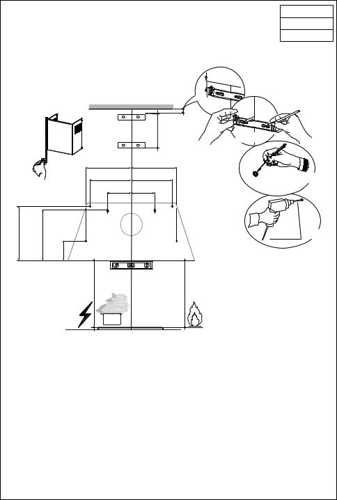
Mark the wall where indicated, 10 7/16" above the horizontal line and at 6 1/2" distance on the left and right of vertical line. Checking that the two marks are level.
Insert two wall plugs and two screws into the holes as shown not completely (purchased separately). Mark the wall where indicated, 3 15/16" above the horizontal line and at 13 12/16" distance on the left and right of vertical line. Checking that the two marks are level. Insert two wall plugs (purchased separately). Mark the wall where indicated, 11" above the horizontal line and at 12 3/16" distance on the left and right of vertical line. Checking that the two marks are level. Insert two wall plugs (purchased separately). Place a bracket 7.2.1 on the wall as shown about 1 1/8" from the ceiling or upper limit, aligning the center (notch) with the vertical reference line and mark the wall at the centers of the holes in the bracket.
Place the second bracket 7.2.1 on the wall as shown, below the first bracket, at the height of the upper chimney section supplied and aligning the center (notch) with the vertical line.
Mark the wall at the centers of the holes in the bracket and drill ø 5/16" as shown.
Installation screws provided for the Brackets, must be secured with wall plugs (purchased separately).
14
2.c |
|
|
|
KMC48X |
|
|
KMC48BI |
|
|
KMC48NE |
|
48" |
|
>1 1/8” |
|
|
||
|
|
|
|
|
||
5 |
6 |
|
|
|
|
|
2.1 |
|
2.1 |
7.2.1 |
|
||
|
|
|
||||
7 |
8 |
|
|
|
|
|
|
18 |
|
9 |
10 |
|
|
18 14/16" |
14/16" |
7 |
8 |
|
||
|
|
5 |
6 |
|
||
11 11/16" |
11 |
11/16" |
3 |
4 |
x10 |
|
1 |
2 |
|||||
|
|
|
|
|||
6 1/2" |
6 1/2" |
|
|
|
|
|
5 |
|
6 |
|
9 |
10 |
|
|
|
|
|
7 |
8 |
|
1 |
|
2 |
|
5 |
6 |
|
|
|
|
|
3 |
4 |
|
|
|
|
|
1 |
2 |
|
11 6/16" 10 7/16" |
|
|
|
Ø 5/16” |
x10 |
|
3 |
|
|
4 |
|
|
|
3 15/16" |
|
|
|
|
|
|
Min. |
|
|
Min. |
|
|
|
24" |
|
|
30" |
|
|
|
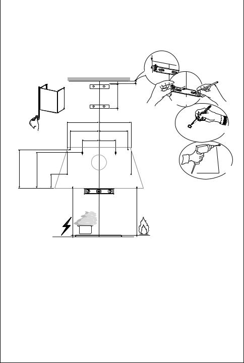
Mark the wall where indicated, 10 7/16" above the horizontal line and at 6 1/2" distance on the left and right of vertical line. Checking that the two marks are level.
Insert two wall plugs and two screws into the holes as shown not completely (purchased separately). Mark the wall where indicated, 3 15/16" above the horizontal line and at 18 14/16" distance on the left and right of vertical line. Checking that the two marks are level. Insert two wall plugs (purchased separately). Mark the wall where indicated, 11 6/16" above the horizontal line and at 11 11/16" distance on the left and right of vertical line. Checking that the two marks are level. Insert two wall plugs (purchased separately). Place a bracket 7.2.1 on the wall as shown about 1 1/8" from the ceiling or upper limit, aligning the center (notch) with the vertical reference line and mark the wall at the centers of the holes in the bracket.
Place the second bracket 7.2.1 on the wall as shown, below the first bracket, at the height of the upper chimney section supplied and aligning the center (notch) with the vertical line.
Mark the wall at the centers of the holes in the bracket and drill ø 5/16" as shown.
Installation screws provided for the Brackets, must be secured with wall plugs (purchased separately).
15

INSTALLATION WITH THE CHIMNEY
3
Remove the filters one at a time, supporting them with one hand and turning the safety knobs (pull and turn).
Do not discard the filters and set aside for future use.
4
Hook and fix the hood body onto the wall.
L
2x
 3/16”
3/16”
OK!
5 


L
4x
From inside fully secure the screws 12a.
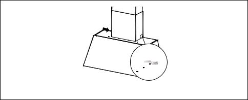
6
12d
4x
3
Use the four screws to secure the angle bracket.
16
|
7 |
|
7 |
Vertical or Horizontal |
|
Ducting Installation |
||
|
N
4x
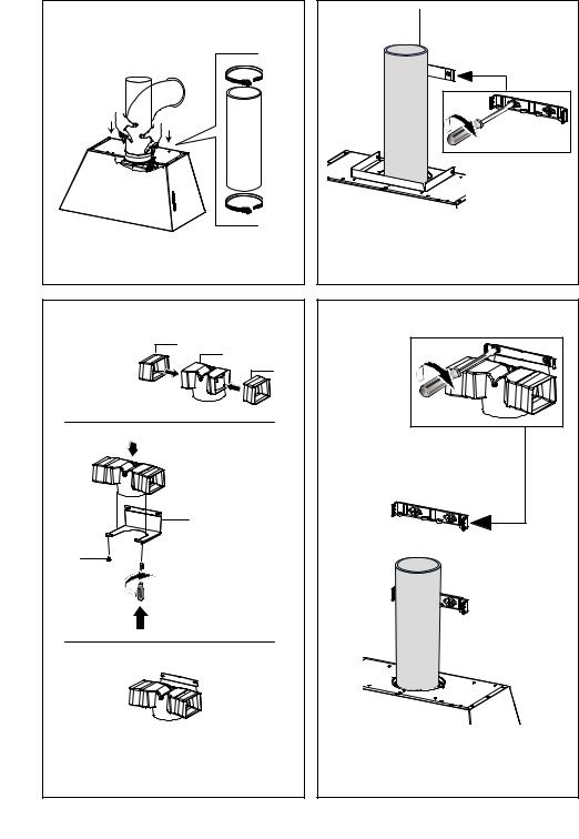
Install Roof or Wall Cap purchased separately. Connect the 6" metal ductwork to the
Roof or Wall Cap and then attach ductwork.
11
10 |
M1 |
4x12b |
|
|
4x |
2.1
N1
8 |
8 |
L |
M |
|
|||
|
|
|
2x |
|
|
4x |
|
Install the 2 fixing bracketsO1
7.2.1 to the middle and upper holes and secure with screws 12a as shown.
|
|
|
11 |
9 |
10 |
|
|
10 |
11 |
||
2.N1
N1
Slightly widen the two sides of the upper chimney and hook them behind the brackets
7.2.1, making sure that they are well seated.
12
11 12
2N1.
N2.2 |
N1 |
|
N2
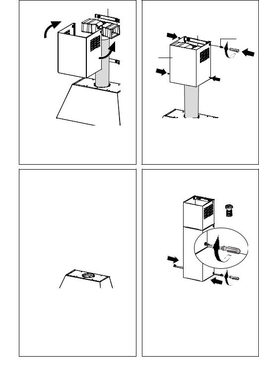
Secure the sides to the brackets by using the 4 screws 12b.
Slightly widen the two sides of the the lower chimney hood and hook them between the upper section and the wall, making sure that they are properly housed.
17
12
12eN
2x
Fix the the lower chimney hood laterally to the hood body using the 2 screws 12e supplied.
18
13 Non-Ducted Recirculation Option
Only for the recirculation version, connect the hood to the Air outlet.
14
Fix the lower Bracket 7.2.1 with two screws 12a supplied as shown.
15
1 |
9.2 |
9.1 |
|
|
9.3 |
2
10e
12f
2x
3
Fix the Ductless Diverter with two screws 12f supplied as shown.
16
Fix the Ductless Diverter with two screws 12a supplied as shown.
19
17
Slightly widen the two sides of the upper chimney and hook them behind the brackets and connect to the Ductless Diverter, making sure that they are well seated.
18
12b
4x
2.1
Secure the sides to the brackets by using the 4 screws 12b.
19
2.2
Slightly widen the two sides of the the lower chimney hood and hook them between the upper section and the wall, making sure that they are properly housed.
20
12eN = 2x
Fix the the lower chimney hood laterally to the hood body using the 2 screws 12e supplied.
20
21
Attach each charcoal filter to the black grid on each side of the blower. Press the charcoal filter tightly to the black grid on the blower side and rotate the filter clockwise (towards the front of the hood) until it locks into place.
Turn counterclockwise (towards the back of the hood) to remove.
Required Activated Charcoal Filter Accessory - sku # - FILTER1 (purchased separately). Long Lasting Charcoal Filter Kit - sku#
FILTER1LL
22 |
Replace the filters one at a time, supporting them with one hand and turning the safety knobs (pull and turn). Do not discard the filters and set aside for future use.
21
 Loading...