

Operating manual
0.37–15 kW

Berges electronic • D–51709 Marienheide-Rodt • Tel. 02264/17-0 • Fax 02264/17126
Parameter Code Summary
PARA-
METER
02-RVLVL Software Revision 35
03-IRAT Inverter Rated Current A 35
07-FLT3 Last Fault 36
08-FLT2 Second Fault 36
09-FLT1 First Fault 36
12-FOUT Motor Output Frequency 0.00–400.0 Hz 36
13-VOUT Motor Output Voltage 0–100%
14-IOUT Motor Output Current 0.00–60.00 A 36
15-LOAD Inverter Load 0–200%
17-TEMP Inverter Temperature 0.00–110.0 °C 36
1A-FSTAT Stator-Frequency
21-MODE Input Mode 3
24-FSEL Speed Setpoint Selector 0
31-FMIN Minimum Frequency 0.00 Hz 0.00–400.0 Hz 38
32-FMAX Maximum Frequency 50.00 Hz 20.00–400.0 Hz 38
33-F2 Preset Frequency 2 5.00 Hz 0.00–400.0 Hz 38
34-F3 Preset Frequency 3 20.00 Hz 0.00–400.0 Hz 38
35-F4 Preset Frequency 4 40.00 Hz 0.00–400.0 Hz 38
36-F5 Preset Frequency 5 50.00 Hz 0.00–400.0 Hz 38
37-F6 Preset Frequency 6 0.00 Hz 0.00–400.0 Hz 38
38-F7 Preset Frequency 7 0.00 Hz 0.00–400.0 Hz 38
39-FTL Minimum Frequency in Torque Limit 10.00 Hz 0.00–400.0 Hz 39
41-RSEL Ramp Selector 0
42-ACC1 Acceleration Time 1 3.00 s 0.10–600.0 s 39
43-DEC1 Deceleration Time 1 3.00 s 0.10–600.0 s 39
44-ACC2 Acceleration Time 2 1.00 s 0.10–600.0 s 40
45-DEC2 Deceleration Time 2 1.00 s 0.10–600.0 s 40
46-DECTL Deceleration Time in Torque Limit 1.00 s 0.10–30.00 s 40
47-DCBRK DC Brake Time 0.20 s 0.00–5.00 s 40
48-DCVLT DC Brake Voltage 2/3 of
51-VSEL V/Hz Characteristic Selector 0 0–5 40
52-BOOST Voltage Boost 8.00% 0.00–25.00% 41
53-FKNEE V/Hz Knee Frequency 50.00 Hz 26.00–400.0 Hz 42
54-SKBND Skip Frequency Hysteresis Band 1.00 Hz 0.20–20.00 Hz 42
55-SK1 Skip Frequency 1 0.00 Hz 0.00–400.0 Hz 42
56-SK2 Skip Frequency 2 0.00 Hz 0.00–400.0 Hz 42
57-SK3 Skip Frequency 3 0.00 Hz 0.00–400.0 Hz 42
59-MVOLT Rated Motor Voltage 230/400 V 185–240 V;
5B-MSAT Motor Saturation Level 47% 15–80% 42
61-LTLF Load Torque Limit Forward 150% 10–150% 42
DESCRIPTION FACTORY
SETTING
52-BOOST
RANGE PAGE CUSTOMER
of line voltage
03-IRAT
of
(1)
Hz
(2)
0–11
(2)
0–19
(2)
0–7
0–15% 40
370–480 V
36
36
55 Read-only
36/55
38/55
39/56
42
SETTING
21.12.98 Operating manual
04_GB ACP 3000 — 0.37–15.0
Berges electronic • D–51709 Marienheide-Rodt • Tel. 02264/17-0 • Fax 02264/17126
PARA-
METER
62-LTLR Load Torque Limit Reverse 150% 10–150% 42
63-RTLF Regenerative Torque Limit Forward 80% 10–110% 42
64-RTLR Regenerative Torque Limit Reverse 80% 10–110% 42
65-SLIP Slip Compensation 0.00%
66-STAB Current Stability Adjustment 3 0–4 43
67-TOL Timed Overload Trip Point 0% 0–100% 43
68-NRST Trip Restart Number 0 0–8 44
69-DRST Restart Delay Time 0.00 s 0.00–60.00 s 44
6A-TOLC Timed Overload Characteristic 0 0–7 45
70-MCAL Analog Meter Output Calibration MET1 Set for10 VDC 0–255 45
71-METER Analog Meter Output Selector MET1 1
72-ST1 Open Collector Output 1 7 0–10 46
75-STR Auxiliary Relay Output 1 0–10 46
77-MOL Motor Overload Input 2 0–3 47
78-MCAL2 Analog Meter Output Calibration MET2 0–20 mA or 4–20 mA;
79-MET2 Analog Meter Output Selector MET2 3
81-PRGNO Special Program/PI Control Characteristics 0 0–9999 48/56
82-START Start Options 1 0–11 48
83-PWM PWM Carrier Frequency Selector 1 0–5 49
84-DISP Display Option Setting 0 0–3000 49
87-ACODE Security Access Code 0 0–999 50
97-RVLVL2 Software Revision Level 2 0.00–12.75 50 Read-only
A1-FCORR Frequency Correction
A6-ERROR2 Final Error
A7-ERROR1 Initial Error
A8-SIPART Integral Sum
B3-KP Proportional Gain
B4-KI Integral Gain
B5-KIN VIN1 Scaling
DESCRIPTION FACTORY
SETTING
set for 20 mA
RANGE PAGE CUSTOMER
(2)
0.00–12.00%
(2)
0–5
0–255 47
(2)
0–15
(1)
0.00–400.0 Hz
(1)
–
(1)
–
(1)
–
(1)
0–255
(1)
0–255
(1)
0–255
43/56
45/56
47/56
55
55 Read-only
55 Read-only
55 Read-only
55
55
55
SETTING
NOTES:
Level 1 Parameters shown shaded.
(1) Additional parameters that are only available when using the PI controller and when
81-PRGNO
the
parameter is set to a value between 80 and 95 (see page 56). See
chapter 6, from page 51 on, for further information about the PI controller.
(2) Extended parameters when using the PI controller. For further information about the
PI controller, see chapter 6, as from page 51.
Operating manual 21.12.98
ACP 3000 — 0.37–15.0 04_GB

Berges electronic • D–51709 Marienheide-Rodt • Tel. 02264/17-0 • Fax 02264/17126
Table of Contents
Page
1 General Information . . . . . . . . . . . . . . . . . . . . . . . . . . . . . . . . . . . . . . . . . . . . . . . . . . . . . . 3
1.1 Explanation of Symbols and Notes . . . . . . . . . . . . . . . . . . . . . . . . . . . . . . . . . . . . . 3
1.2 Safety and Operating Instructions for Drive Converters. . . . . . . . . . . . . . . . . . . . . . 3
1.3 Preface. . . . . . . . . . . . . . . . . . . . . . . . . . . . . . . . . . . . . . . . . . . . . . . . . . . . . . . . . . . 5
2 Technical Data . . . . . . . . . . . . . . . . . . . . . . . . . . . . . . . . . . . . . . . . . . . . . . . . . . . . . . . . . . 6
2.1 Model Identification Number . . . . . . . . . . . . . . . . . . . . . . . . . . . . . . . . . . . . . . . . . . 6
2.2 Power Specifications . . . . . . . . . . . . . . . . . . . . . . . . . . . . . . . . . . . . . . . . . . . . . . . . 6
2.3 General Drive Specifications . . . . . . . . . . . . . . . . . . . . . . . . . . . . . . . . . . . . . . . . . . 7
2.4 Dimensional Data (Size I) . . . . . . . . . . . . . . . . . . . . . . . . . . . . . . . . . . . . . . . . . . . . 8
2.4.1 Dimensional Data (Size II). . . . . . . . . . . . . . . . . . . . . . . . . . . . . . . . . . . . . . . . . . . . 9
2.4.2 Dimensional Data (Size III) . . . . . . . . . . . . . . . . . . . . . . . . . . . . . . . . . . . . . . . . . . . 9
2.4.3 Dimensional Data (Size IV) . . . . . . . . . . . . . . . . . . . . . . . . . . . . . . . . . . . . . . . . . . 10
3 Installation. . . . . . . . . . . . . . . . . . . . . . . . . . . . . . . . . . . . . . . . . . . . . . . . . . . . . . . . . . . . . 11
3.1 Inspection. . . . . . . . . . . . . . . . . . . . . . . . . . . . . . . . . . . . . . . . . . . . . . . . . . . . . . . . 11
3.2 General Rules for Installation. . . . . . . . . . . . . . . . . . . . . . . . . . . . . . . . . . . . . . . . . 11
3.3 EMC (Electromagnetic Compatibility) . . . . . . . . . . . . . . . . . . . . . . . . . . . . . . . . . . 12
3.3.1 Suggestion on how to solve the Problem of Radio Frequency Interference
Suppression of Frequency Converters to VDE 0875/EN 55011 . . . . . . . . . . . . . . 12
3.3.2 Mains Filters/Output Chokes . . . . . . . . . . . . . . . . . . . . . . . . . . . . . . . . . . . . . . . . . 13
3.3.3 Filter Specifications . . . . . . . . . . . . . . . . . . . . . . . . . . . . . . . . . . . . . . . . . . . . . . . . 14
3.3.4 Interference Suppression Measures . . . . . . . . . . . . . . . . . . . . . . . . . . . . . . . . . . . 15
3.4 EMC Ordinance (EMC Directive, 89/336 EEC) . . . . . . . . . . . . . . . . . . . . . . . . . . . 17
3.5 Wiring Practices. . . . . . . . . . . . . . . . . . . . . . . . . . . . . . . . . . . . . . . . . . . . . . . . . . . 18
3.5.1 Applicable Codes. . . . . . . . . . . . . . . . . . . . . . . . . . . . . . . . . . . . . . . . . . . . . . . . . . 18
3.5.2 Power Wiring . . . . . . . . . . . . . . . . . . . . . . . . . . . . . . . . . . . . . . . . . . . . . . . . . . . . . 18
3.5.3 Control Wiring/Interface . . . . . . . . . . . . . . . . . . . . . . . . . . . . . . . . . . . . . . . . . . . . . 18
3.6 Mains Power Connection. . . . . . . . . . . . . . . . . . . . . . . . . . . . . . . . . . . . . . . . . . . . 19
3.6.1 Mains Conditions . . . . . . . . . . . . . . . . . . . . . . . . . . . . . . . . . . . . . . . . . . . . . . . . . . 20
3.6.2 Line Protection. . . . . . . . . . . . . . . . . . . . . . . . . . . . . . . . . . . . . . . . . . . . . . . . . . . . 21
3.6.3 Using Mains Filters. . . . . . . . . . . . . . . . . . . . . . . . . . . . . . . . . . . . . . . . . . . . . . . . . 22
3.6.4 Line Starting. . . . . . . . . . . . . . . . . . . . . . . . . . . . . . . . . . . . . . . . . . . . . . . . . . . . . . 23
3.7 Motor Connection. . . . . . . . . . . . . . . . . . . . . . . . . . . . . . . . . . . . . . . . . . . . . . . . . . 23
3.8 Reducing Current Surges and Voltage Transients. . . . . . . . . . . . . . . . . . . . . . . . . 23
3.9 Function and Use of Terminals . . . . . . . . . . . . . . . . . . . . . . . . . . . . . . . . . . . . . . . 24
3.10 Terminal Access Cover Removal. . . . . . . . . . . . . . . . . . . . . . . . . . . . . . . . . . . . . . 25
3.11 Terminal Assignment (Mains supply 1 × 230 VAC, 0.37–4.0 kW) . . . . . . . . . . . . . 26
3.12 Terminal Assignment (Mains supply 3 × 400 VAC, 0.37–4.0 kW) . . . . . . . . . . . . . 26
3.13 Terminal Assignment (Mains supply 3 × 400 VAC, 5.5–15.0 kW) . . . . . . . . . . . . . 27
3.14 Remote Keypad/Program Memory Unit Connector (J22) . . . . . . . . . . . . . . . . . . . 27
3.15 Control Terminal Description . . . . . . . . . . . . . . . . . . . . . . . . . . . . . . . . . . . . . . . . . 27
3.16 J20 Configuration. . . . . . . . . . . . . . . . . . . . . . . . . . . . . . . . . . . . . . . . . . . . . . . . . . 29
21.12.98 Operating manual
04_GB ACP 3000 — 0.37–15.0
1

Berges electronic • D–51709 Marienheide-Rodt • Tel. 02264/17-0 • Fax 02264/17126
Page
4 Getting Started . . . . . . . . . . . . . . . . . . . . . . . . . . . . . . . . . . . . . . . . . . . . . . . . . . . . . . . . .30
4.1 General Information . . . . . . . . . . . . . . . . . . . . . . . . . . . . . . . . . . . . . . . . . . . . . . . . 30
4.2 Digital Keypad . . . . . . . . . . . . . . . . . . . . . . . . . . . . . . . . . . . . . . . . . . . . . . . . . . . . 30
4.3 Keypad Operation . . . . . . . . . . . . . . . . . . . . . . . . . . . . . . . . . . . . . . . . . . . . . . . . . 30
4.4 Operation Mode (RUN and STOP Modes). . . . . . . . . . . . . . . . . . . . . . . . . . . . . . . 31
4.5 Program Mode . . . . . . . . . . . . . . . . . . . . . . . . . . . . . . . . . . . . . . . . . . . . . . . . . . . . 31
4.6 Status Indicator . . . . . . . . . . . . . . . . . . . . . . . . . . . . . . . . . . . . . . . . . . . . . . . . . . . 32
4.7 Description of Displays. . . . . . . . . . . . . . . . . . . . . . . . . . . . . . . . . . . . . . . . . . . . . . 32
4.8 Programming Tips . . . . . . . . . . . . . . . . . . . . . . . . . . . . . . . . . . . . . . . . . . . . . . . . .33
4.9 Quick Start . . . . . . . . . . . . . . . . . . . . . . . . . . . . . . . . . . . . . . . . . . . . . . . . . . . . . . . 34
5 Parameter Configuration and Description . . . . . . . . . . . . . . . . . . . . . . . . . . . . . . . . . . . 35
5.1 Programming . . . . . . . . . . . . . . . . . . . . . . . . . . . . . . . . . . . . . . . . . . . . . . . . . . . . . 35
5.2 Parameter Descriptions . . . . . . . . . . . . . . . . . . . . . . . . . . . . . . . . . . . . . . . . . . . . . 35
6 PI Controller . . . . . . . . . . . . . . . . . . . . . . . . . . . . . . . . . . . . . . . . . . . . . . . . . . . . . . . . . . . 51
6.1 Introduction . . . . . . . . . . . . . . . . . . . . . . . . . . . . . . . . . . . . . . . . . . . . . . . . . . . . . . 51
6.2 Overview of PI Control . . . . . . . . . . . . . . . . . . . . . . . . . . . . . . . . . . . . . . . . . . . . . . 51
6.3 Reference and Feedback Inputs . . . . . . . . . . . . . . . . . . . . . . . . . . . . . . . . . . . . . . 53
6.4 Calculating PI Controller Values. . . . . . . . . . . . . . . . . . . . . . . . . . . . . . . . . . . . . . . 54
6.5 Parameters for PI Control. . . . . . . . . . . . . . . . . . . . . . . . . . . . . . . . . . . . . . . . . . . . 54
7 Connection Diagrams. . . . . . . . . . . . . . . . . . . . . . . . . . . . . . . . . . . . . . . . . . . . . . . . . . . . 58
7.1 AC Line and Motor Connections (Mains supply 1 × 230 VAC and 3 × 400 VAC) . 58
7.2 2-Wire Run/Stop Connections . . . . . . . . . . . . . . . . . . . . . . . . . . . . . . . . . . . . . . . . 59
7.3 3-Wire Run/Stop Connections . . . . . . . . . . . . . . . . . . . . . . . . . . . . . . . . . . . . . . . . 59
7.4 Auxiliary Relay Output and Digital Output ST1 . . . . . . . . . . . . . . . . . . . . . . . . . . . 59
7.5 MOL Terminal Connections . . . . . . . . . . . . . . . . . . . . . . . . . . . . . . . . . . . . . . . . . . 60
7.6 Analog Speed Input Connections (VIN1/VIN2) . . . . . . . . . . . . . . . . . . . . . . . . . . . 60
7.7 Optional Connections. . . . . . . . . . . . . . . . . . . . . . . . . . . . . . . . . . . . . . . . . . . . . . .61
8 Troubleshooting . . . . . . . . . . . . . . . . . . . . . . . . . . . . . . . . . . . . . . . . . . . . . . . . . . . . . . . . 62
8.1 Special Indications . . . . . . . . . . . . . . . . . . . . . . . . . . . . . . . . . . . . . . . . . . . . . . . . . 62
8.2 Fault Trip Indications . . . . . . . . . . . . . . . . . . . . . . . . . . . . . . . . . . . . . . . . . . . . . . .62
8.3 Resetting a Fault . . . . . . . . . . . . . . . . . . . . . . . . . . . . . . . . . . . . . . . . . . . . . . . . . . 63
8.4 Fault Codes . . . . . . . . . . . . . . . . . . . . . . . . . . . . . . . . . . . . . . . . . . . . . . . . . . . . . .63
9 Appendix . . . . . . . . . . . . . . . . . . . . . . . . . . . . . . . . . . . . . . . . . . . . . . . . . . . . . . . . . . . . . . 65
9.1 Parameter Code Summary. . . . . . . . . . . . . . . . . . . . . . . . . . . . . . . . . . . . . . . . . . . 65
9.2 Parameters Added or Amended when PI Control is Utilized . . . . . . . . . . . . . . . . . 67
9.3 Options. . . . . . . . . . . . . . . . . . . . . . . . . . . . . . . . . . . . . . . . . . . . . . . . . . . . . . . . . .67
2
Operating manual 21.12.98
ACP 3000 — 0.37–15.0 04_GB
Berges electronic • D–51709 Marienheide-Rodt • Tel. 02264/17-0 • Fax 02264/17126
1 General Information
1.1 Explanation of Symbols and Notes
Work Safety Symbol
You will find this symbol next to all work safety notes in this operating manual if there is a
risk of injury or death for persons involved. Pay attention to these notes and observe particular caution in such cases. Also pass on all work safety instructions to other users.
Voltage Warning
This symbol is shown wherever particular caution is necessary owing to occurring or applied voltages (e.g. DC voltages up to 650 V) and where special precautionary measures
have to be taken. The inverter must always be isolated from the mains when working on it.
Caution Note
ATTENTION!
This note is shown in all parts of this operating manual to which particular attention must be
paid to ensure that the guidelines, specifications, notes and the correct sequence of work
will be obeyed and to prevent damage or destruction of the inverter and/or systems.
1.2 Safety and Operating Instructions for Drive Converters
1. General
In operation, drive converters, depending on their degree of protection, may have live,
unisolated, and possibly also moving or rotating parts, as well as hot surfaces.
In case of inadmissible removal of the required covers, of improper use, wrong installation
or maloperation, there is the danger of serious personal injury and damage to property.
For further information, see documentation.
All operations serving transport, installation and commissioning as well as maintenance are
to be carried out by skilled technical personnel (Observe IEC 364 or CENELEC HD 384
or DIN VDE 0100 and IEC 664 or DIN/VDE 0110 and national accident prevention rules!).
For the purposes of these basic safety instructions, “skilled technical personnel” means persons who are familiar with the installation, mounting, commissioning and operation of the
product and have the qualifications needed for the performance of their functions.
We draw attention to the fact that no liability can be assumed for damage and malfunctions
resulting from failure to observe the operating manual.
Technical amendments of illustrations and data given in this operating manual are reserved
in the interest of improving the unit and its functions.
2. Intended Use
The application of the drive converter described in this operating manual exclusively serves
the purpose of continuously variable speed control of three-phase motors.
Drive converters are components designed for inclusion in electrical installations or machinery.
The drive converters are designed for installation in a switchgear cabinet and for permanent
connection.
The operator of the system is solely liable for damage resulting from improper use of the
drive converter.
21.12.98 Operating manual
04_GB ACP 3000 — 0.37–15.0
3

Berges electronic • D–51709 Marienheide-Rodt • Tel. 02264/17-0 • Fax 02264/17126
Only items expressly approved by BERGES (e.g. mains filter, choke, external braking choppers and braking resistors etc.) may be used as accessories.
The installer of the system is liable for any damage resulting from the use of accessories
that have not been approved expressly by BERGES. Please consult us in case of doubt.
In case of installation in machinery, commissioning of the drive converters (i.e. the starting
of normal operation) is prohibited until the machinery has been proved to conform to the
provisions of the directive 89/392/EEC (Machinery Safety Directive – MSD). Account is to
be taken of EN 60204.
Commissioning (i.e. the starting of normal operation) is admissible only where conformity
with the EMC directive (89/336/EEC) has been established.
The drive converters meet the requirements of the low-voltage directive 73/23/EEC. They
are subject to the harmonized standards of the series prEN 50178/DIN VDE 0160 in conjunction with EN 60439-1/DIN VDE 0660, part 500, and EN 60146/DIN VDE 0558.
The technical data as well as information concerning the supply conditions shall be taken
from the rating plate and from the documentation and shall be strictly observed.
3. Transport, Storage
The instructions for transport, storage and proper use shall be complied with.
Damage established after delivery must be notified to the transport company immediately.
Where necessary, the supplier must also be notified before the damaged drive converter is
put into operation.
The climatic conditions shall be in conformity with prEN 50178.
4. Installation
The installation and cooling of the appliances shall be in accordance with the specifications
in the pertinent documentation.
The drive converters shall be protected against excessive strains. In particular, no components must be bent or isolating distances altered in the course of transportation or handling.
No contact shall be made with electronic components and contacts.
Drive converters contain electrostatic sensitive components which are liable to damage
through improper use. Electric components must not be mechanically damaged or destroyed (potential health risks).
5. Electrical Connection
When working on live drive converters, the applicable national accident prevention rules
(e.g. VBG 4) must be complied with.
The electrical installation shall be carried out in accordance with the relevant requirements
(e.g. cross-sectional areas of conductors, fusing, PE connection). For further information,
see documentation.
Instructions for the installation in accordance with EMC requirements, like screening, earthing, location of filters and wiring, are contained in the drive converter documentation. They
must always be complied with, also for drive converters bearing a CE marking. Observance
of the limit values required by EMC law is the responsibility of the manufacturer of the installation or machine.
4
6. Operation
The components of the power section and certain elements of the control section are connected to the voltage mains when the drive converter is connected to the mains voltage.
Touching these components involves mortal danger!
Always isolate the drive converter from the mains supply before performing any work on the
electrical or mechanical part of the system.
Operating manual 21.12.98
ACP 3000 — 0.37–15.0 04_GB

Berges electronic • D–51709 Marienheide-Rodt • Tel. 02264/17-0 • Fax 02264/17126
Isolate the drive converter from the mains before removing the terminal cover or the housing (e.g. by removing or deactivating on-site fuses or by deactivating a master switch isolating all poles etc.).
After disconnection of the drive converters from the voltage supply, live appliance parts and
power terminals must not be touched immediately because of possibly energized capacitors. In this respect, the corresponding signs and markings on the drive converter must be
respected. After switching off the mains voltage, wait for at least 5 minutes before beginning work on or in the drive converter. Dangerous voltages are still present as long as the
“STATUS” lamp is still lit. In the event of malfunctions, the discharge time of 5 minutes may
be exceeded substantially.
The drive converter contains protective facilities that deactivate it in the event of malfunctions, whereby the motor is de-energized and comes to a standstill (so-called “coasting” of
the motor is possible depending on the rotating mass of the type of drive involved). Standstill of the motor can, however, also be produced by mechanical blockage. Voltage fluctuations, and particularly mains power failures, may also lead to deactivation. In certain
circumstances, the drive may start up automatically once the cause of the fault has been
remedied. As a result of this, certain systems may be damaged or destroyed and there may
be a risk for operators working on the system. Installations which include drive converters
shall be equipped with additional control and protective devices in accordance with the relevant applicable safety requirements, e.g. Act respecting technical equipment, accident
prevention rules etc. Changes to the drive converters by means of the operating software
are admissible.
1.3 Preface
The motor may be stopped during operation by disabling it or by deactivating the setpoint,
whereby the drive converter and motor may remain live. If inadvertent start-up of the mo-
tor must be excluded to protect operating personnel, electronic interlocking by disabling the motor or by deactivating the setpoint is inadequate. This is why the drive
converter must be isolated from the mains voltage.
During operation, all covers and doors shall be kept closed.
Measuring instruments must be connected and disconnected only in de-energized condi-
tion.
Unauthorized conversions or modifications on or in the drive converter and its components
and accessories will render all warranty claims void.
Please contact BERGES if conversions or modifications are necessary, particularly if elec-
trical components are involved.
7. Maintenance and Servicing
The manufacturer's documentation shall be followed.
KEEP SAFETY INSTRUCTIONS IN A SAFE PLACE!
Before you read on, please check whether technical changes are at-
tached in the annex to this operating manual!
The present manual contains the specifications, installation instructions, description of operation and troubleshooting procedures for ACP 3000 inverters. The information in this
manual must be known before installation of the inverter in order to guarantee fault-free installation and thus maximum performance.
21.12.98 Operating manual
04_GB ACP 3000 — 0.37–15.0
5
Berges electronic • D–51709 Marienheide-Rodt • Tel. 02264/17-0 • Fax 02264/17126
2 Technical Data
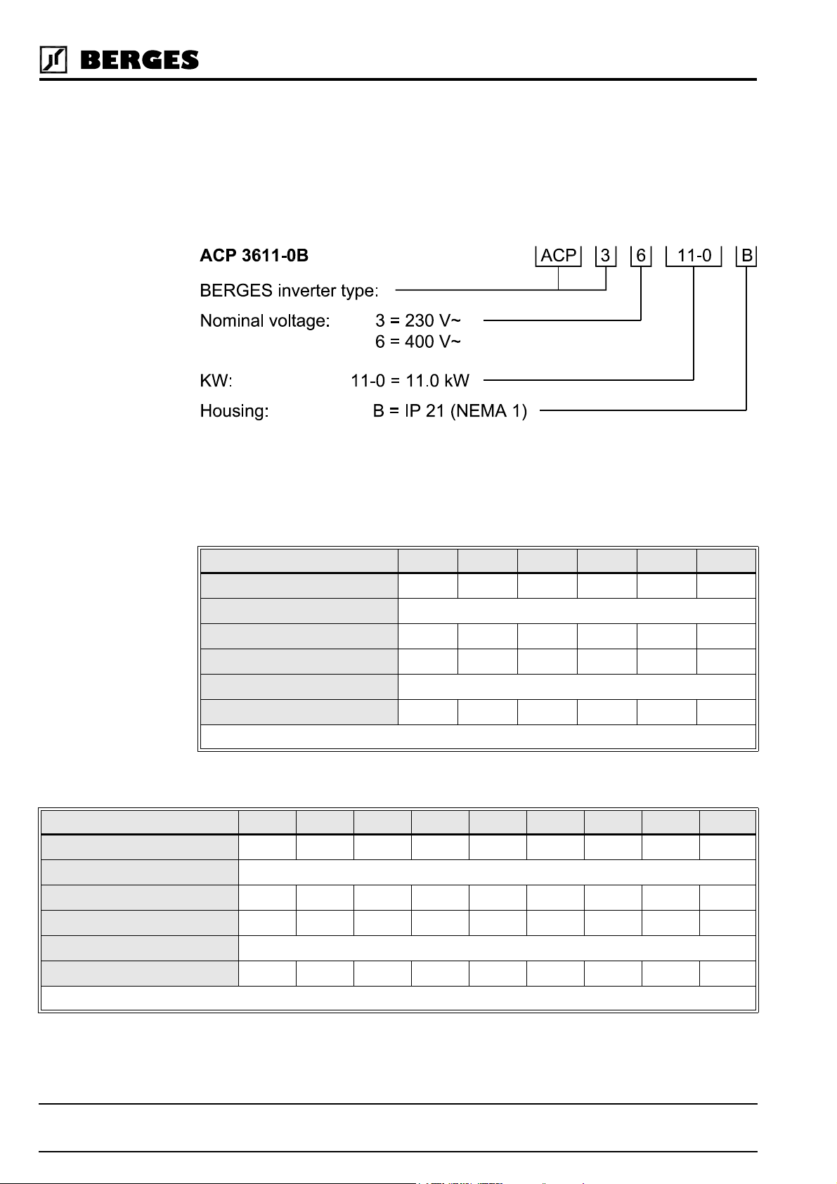
2.1 Model Identification Number
All ACP 3000 models bear a systematic identification number designating the rated input
voltage, the rated power and the housing type. This model number appears both on the
shipping carton label and the technical data label on the drive.
Example type marking
2.2 Power Specifications
Models with Supply Voltage 1 × 230 VAC
Model ACP 3300-3 3300-5 3300-7 3301-1 3301-5 3302-2
Kilowatt (kW) 0.37 kW 0.55 kW 0.75 kW 1.1 kW 1.5 kW 2.2 kW
Output Voltage Three Phase 3.5–230 VAC
Rated current 1.94 A 2.6 A 3.4 A 4.8 A 6.4 A 9.0 A
Maximum Output Current * 2.1 A 2.9 A 3.7 A 5.3 A 7.0 A 9.9 A
Input Volts (±10%) 208–230 V~
Maximum Input Current 3.1 A 4.7 A 6.4 A 9.4 A 12.7 A 18.6 A
Table 2.1
Models with Supply Voltage 3 × 400 VAC
Model ACP 3600-7 3601-5 3602-2 3603-0 3604-0 3605-5 3607-5 3611-0 3615-0
Kilowatt (kW) 0.75 kW 1.5 kW 2.2 kW 3.0 kW 4.0 kW 5.5 kW 7.5 kW 11.0 kW 15.0 kW
Output Voltage Three Phase 7.0–460 VAC
Rated current 1.95 A 3.7 A 5.2 A 6.8 A 9.2 A 13.0 A 18.0 A 24.0 A 30.0 A
Maximum Output Current * 2.1 A 4.1 A 5.7 A 7.5 A 10.1 A 14.3 A 19.8 A 26.4 A 33.0 A
Input Volts (±10%) 400–460 V~
Maximum Input Current 2.11 A 4.2 A 6.2 A 8.4 A 11.2 A 16.0 A 22.2 A 31.0 A 37.9 A
Table 2.2
6
* = Maximum inverter capacity. Value = 1.1 ×
Operating manual 21.12.98
ACP 3000 — 0.37–15.0 04_GB
03-IRAT
(see page 35).
Berges electronic • D–51709 Marienheide-Rodt • Tel. 02264/17-0 • Fax 02264/17126
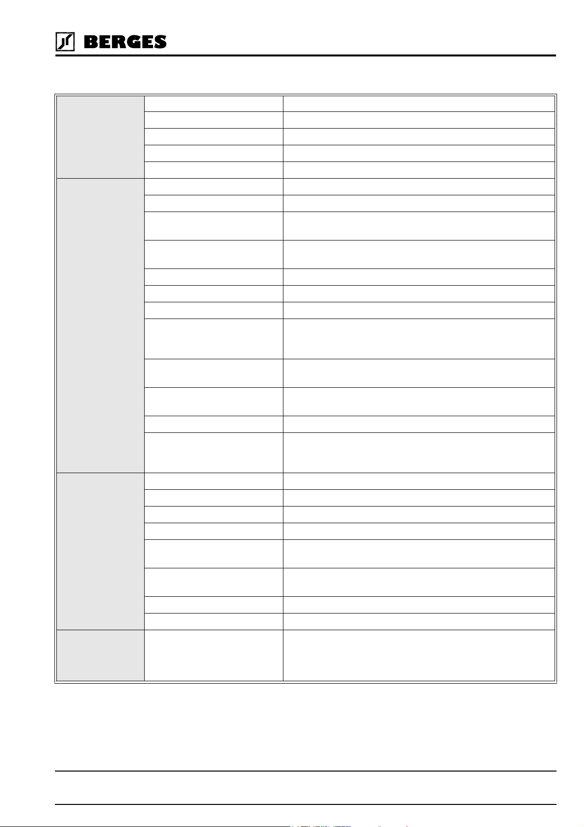
2.3 General Drive Specifications
Inverter
Power Ratings
Control
Specifications
Input Frequency 50/60 Hz (±2%)
Phase Imbalance (3 ∅ only) ±2%
Overload Capacity 150% for 60 seconds
Running Torque 100% at 3 Hz
Starting Torque Greater than 100%
Control System Sine-weighted voltage vector (PWM)
PWM Frequency 4–16 kHz (plus Autoselect feature)
Frequency Range 1.00–400.0 Hz programmable in 0.05 Hz increments
(0.1 Hz above 99.95 Hz)
Frequency resolution 0.05 Hz up 0.00 to 99.95 Hz,
0.1 Hz above 100.0 Hz
Minimum Frequency 0.00–400.0 Hz
Maximum Frequency 20.00–400.0 Hz
Preset Speeds Up to 8 available; programmable to maximum frequency
Frequency Command
Selections
Acceleration and Deceleration
Range
V/Hz Ratio 0.19–9.23 V/Hz (230 VAC models)
Torque Limit Automatic or fixed adjustment possible
0–5 VDC, 0–10 VDC, 0–20 mA, 4–20 mA, direct or inverted;
Digital Keypad; Program Memory Unit; Remote Keypad Unit;
external Potentiometer
Programmable 0.1 to 600 seconds to maximum frequency
(2 Each)
0.39–18.46 V/Hz (400 VAC models)
Protection
Features
Operating
Features
Dynamic Braking Up to 60% for 6 sec. with standard DB resistor; higher braking
power values can be achieved by means of an external braking
chopper (option)
Ground Fault Protected from damage
Short Circuit Protected from damage
Motor Overload Programmable inverse time overload trip
Torque Limit All four quadrants individually programmable
Overvoltage Short voltage peaks are bridged; an error is triggered if an ov-
ervoltage lasts for longer than 500 ms
Undervoltage Short voltage dips are bridged; a defined “Restart” is performed
if an undervoltage lasts for longer than 200 ms
Over Temperature Protected from damage, warning display
MOL Input Terminal Programmable for N.C. or N.O. contacts
Operating Controls 1. Keypad.
2. Remote keypad unit.
3. Terminal strip.
4. Program memory unit.
21.12.98 Operating manual
04_GB ACP 3000 — 0.37–15.0
7
Berges electronic • D–51709 Marienheide-Rodt • Tel. 02264/17-0 • Fax 02264/17126
®
Operating
Features
LED Indicators Red and Green for operation and fault annunciation
Keypad Display 6 digit, backlit LCD with special annunciators
and unit symbols
Auxiliary Relay Programmable analog output;
programmable status signalling relay
Programming Levels Level 1 – Operator
Level 2 – Engineer
Inputs/Outputs Inputs 6 Digital: Pull-up or pull-down logic
2 Analog: VIN1 Current or voltage;
VIN2 Voltage only
Outputs 2 Digital: 1 Open collector (internal or external power supply)
up to 24 VDC;
1 Relay (Form C)
2 Analog: MET1 (0 to 10 VDC);
MET2 (0/4 to 20 mA DC)
Ambient
Conditions
Operating Temperature 0 °C to +40 °C (IP 21 models)
0 °C to +50 °C (with detached cover)
Storage temperature -20 °C to +60 °C
Humidity 90% RH or less, non-condensing
Vibration 0.6 G Maximum
Elevation 1000 Meters (3,300 Feet) without derating
UL-/CSA-
Agency Listings
Certifications
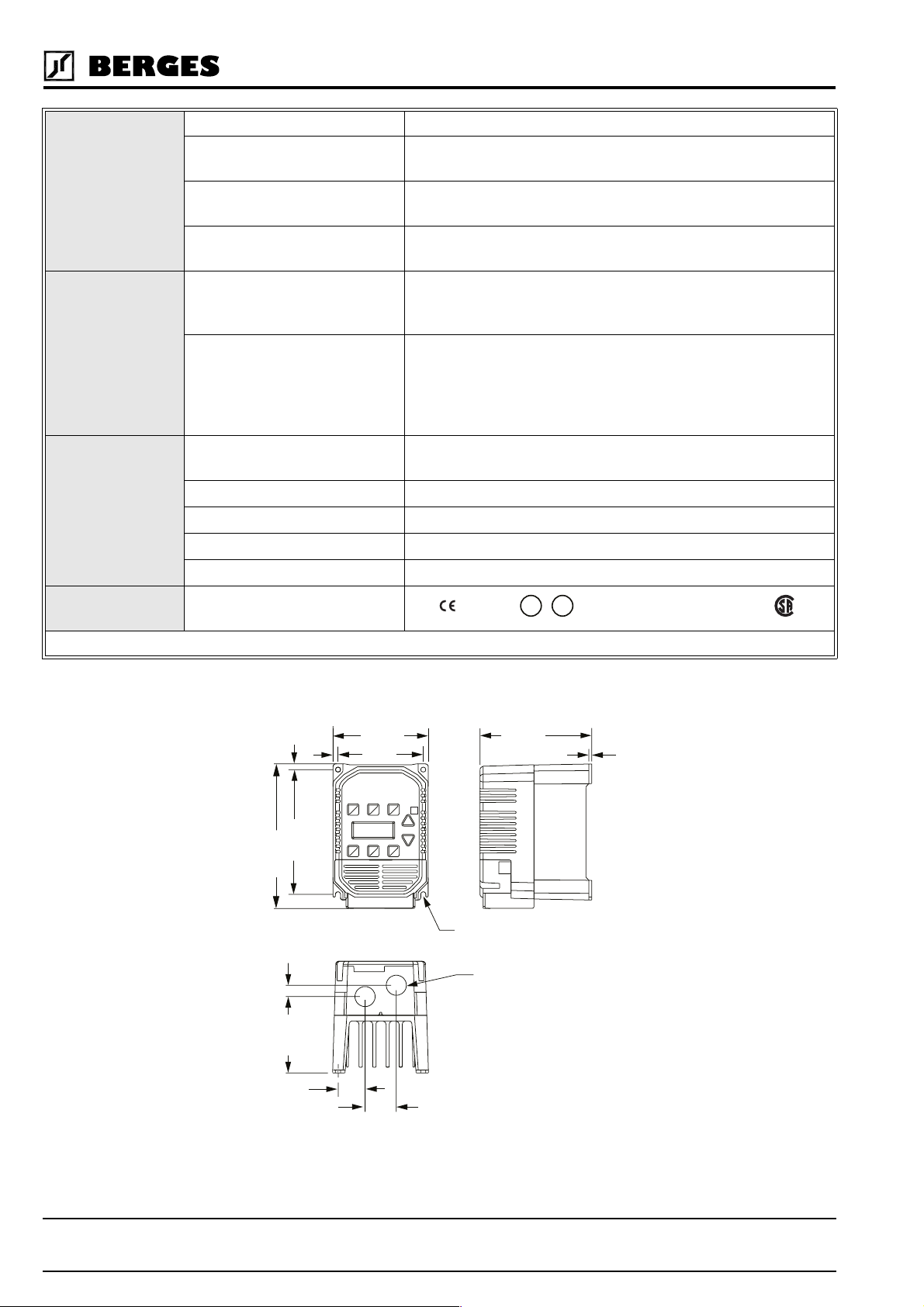
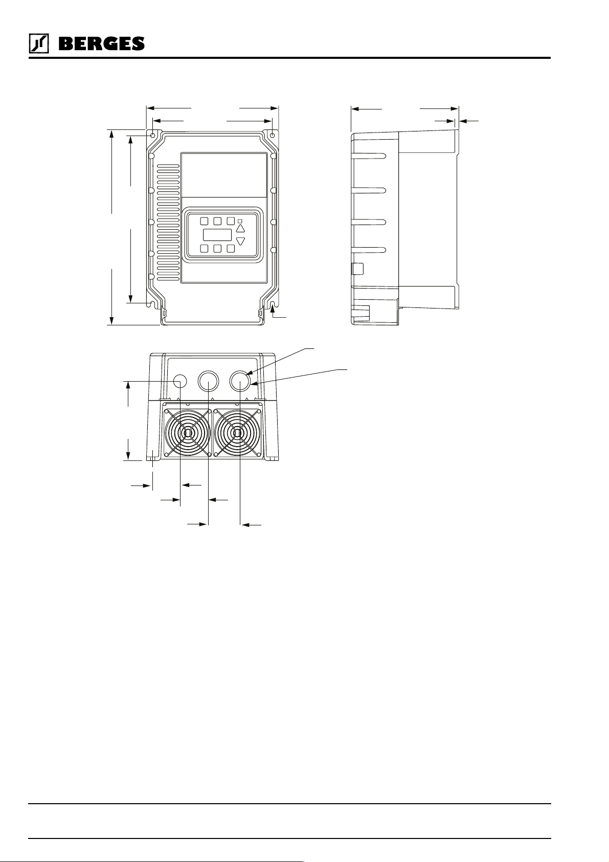
2.4 Dimensional Data (Size I)
6
137
159
12
U
Marked, UL/cUL listed, CSA-certified
U
C
®
®
L
L
Table 2.3
105
5
94
∅ 5.5
Size for devices:
123
3
∅ 22
I
84
30
ACP 3300-3 (230 V)
ACP 3300-5 (230 V)
ACP 3600-7 (400 V)
Weight: 1.4 kg
34
Operating manual 21.12.98
8
ACP 3000 — 0.37–15.0 04_GB
Berges electronic • D–51709 Marienheide-Rodt • Tel. 02264/17-0 • Fax 02264/17126
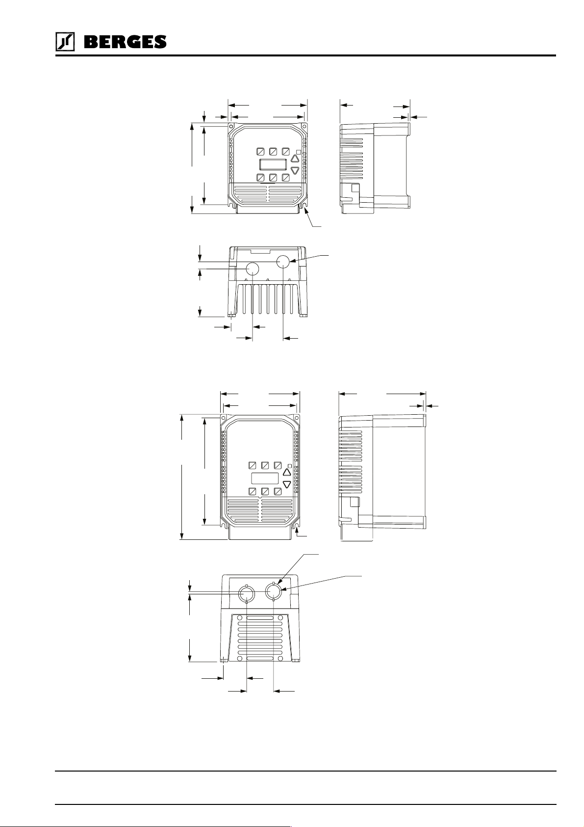
2.4.1 Dimensional Data (Size II)
6
5
137
159
12
84
38
140
129
2.4.2 Dimensional Data (Size III)
∅ 5.5
∅ 22
II
Size for devices:
ACP 3300-7 (230 V)
ACP 3301-1 (230 V)
ACP 3601-5 (400 V)
Weight: 1.9 kg
54
125
3
220
119
140
129
153
5
188
∅ 5.5
∅ 29
5
Size for devices:
∅ 22
III
ACP 3301-5 (230 V)
ACP 3302-2 (230 V)
ACP 3602-2 (400 V)
ACP 3603-0 (400 V)
ACP 3604-0 (400 V)
41
Weight: 3.45 kg
47
21.12.98 Operating manual
04_GB ACP 3000 — 0.37–15.0
9
Berges electronic • D–51709 Marienheide-Rodt • Tel. 02264/17-0 • Fax 02264/17126
2.4.3 Dimensional Data (Size IV)
327
280
221
200
∅ 5.5
∅ 29
∅ 35
Size for devices:
IV
180
6
133
46
ACP 3605-5 (400 V)
ACP 3607-5 (400 V)
ACP 3611-0 (400 V)
ACP 3615-0 (400 V)
Weight: 8.6 kg
47
53
10
Operating manual 21.12.98
ACP 3000 — 0.37–15.0 04_GB
Berges electronic • D–51709 Marienheide-Rodt • Tel. 02264/17-0 • Fax 02264/17126
3 Installation
3.1 Inspection
A. Upon receipt, unpack and carefully inspect for any damage sustained in transit (depres-
sion in the enclosure, damage to parts, missing parts).
B. Remove the cover (see page 25) and inspect the inverter for any apparent damage or
foreign objects. Ensure that all mounting hardware and terminal connection hardware is
properly seated, securely fastened, and undamaged.
C. Read the technical data label and ensure that the correct rated output and input voltage
for the application has been purchased.
D. If the inverter is to be stored for a long period of time, repack and store in a clean, dry
place, free from direct sunlight or corrosive fumes, and in a location where the ambient
temperature will not be less then -20 °C nor more than +60 °C.
3.2 General Rules for Installation
Improper installation of the inverter will greatly effect its life. Be sure to observe the following
points when selecting a mounting location. VIOLATING THE CONDITIONS LISTED BE-
LOW MAY VOID THE WARRANTY!
A. Mount the unit vertically and do not restrict the airflow to the heat sink fins on the back
of the controller. The fan and fins allow cooling of internal components. Any air restriction could greatly reduce the life of the inverter, as well as resulting in nuisance overtemperature trips.
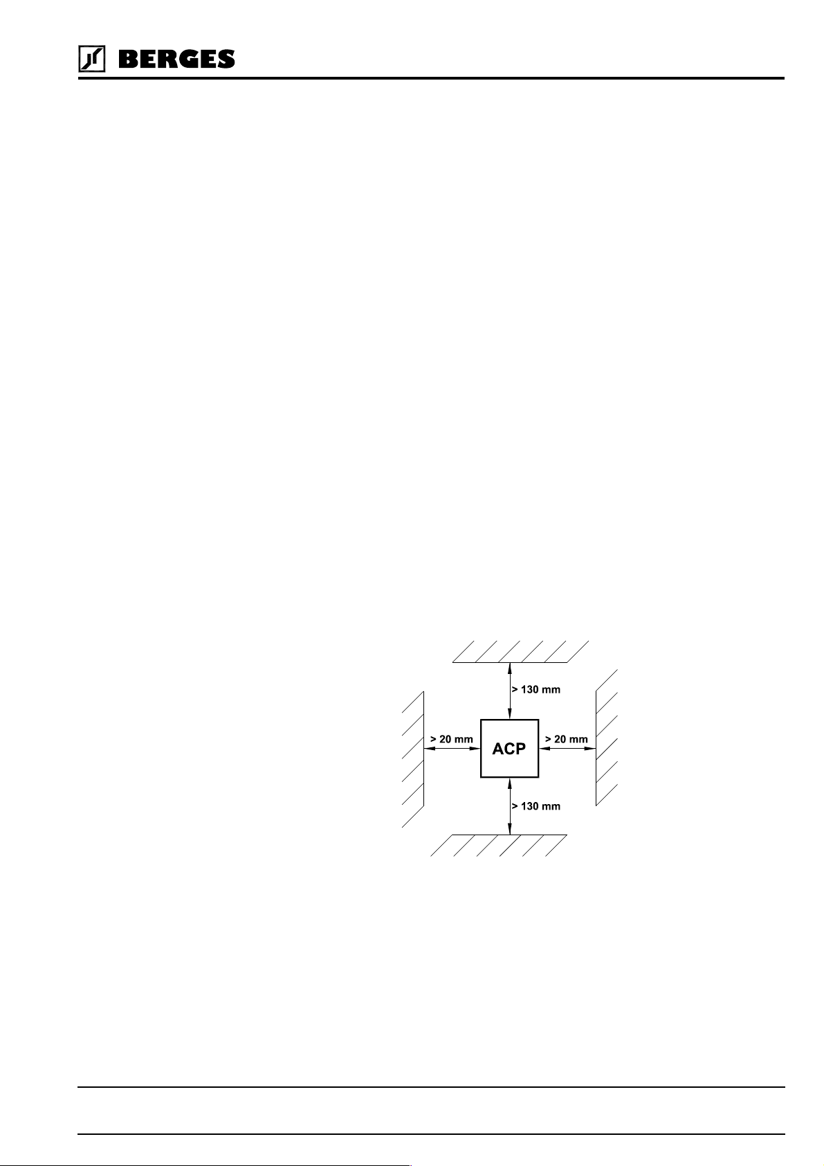
B. The ACP inverter generates heat, and therefore there must be a sufficient amount of
free space around the unit (see Figure 3.1). If the unit is accommodated in a housing
together with a different unit, the prescribed minimum distances must be observed so
that adequate ventilation can be ensured.
Figure 3.1
C. If the inverter has to be installed in a different position, external cooling is required for
full capacity utilization. In certain circumstances, the internal air circulation does not suffice when installing the unit in a control cabinet with a small volume. Therefore, when
installing the unit, you must ensure that a heat buildup is prevented.
D. Do not mount the ACP near heat generating equipment, or in direct sunlight. BERGES
inverters are generally designed so that they can be operated at ambient temperatures
of 0 °C to +50 °C (IP 00) or 0 °C to 40 °C (IP 21) and at a relative humidity of up to 90%.
The occurrence of condensate must be avoided!
21.12.98 Operating manual
04_GB ACP 3000 — 0.37–15.0
11
Berges electronic • D–51709 Marienheide-Rodt • Tel. 02264/17-0 • Fax 02264/17126
E. Do not install the inverter in a place subjected to high temperature, high humidity, or ex-
cessive vibration (see Table 2.3, “Ambient Conditions”)
F. The units should never be installed in the proximity of corrosive or flammable gases,
conductive dust or large magnetic and electric fields.
G. Pay close attention during installation to ensuring that no objects (such as drilling swarf,
wire or anything else) fall into the unit. Otherwise, a device fault cannot be excluded,
even after longer periods of operation.
ATTENTION!
H. Do not use wire end ferrules for the control terminals. The terminals are designed
so that the wires can be inserted in the terminals after twisting the individual
wires.
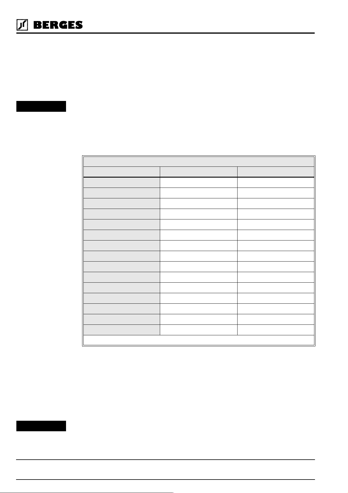
I. Table 3.1 shows the watts generated by the inverter when at full current. The heat gen-
erated is dependent on the carrier frequency used. For carrier frequencies other than
those shown in Table 3.1, consult BERGES or use the worst-case scenario (16 kHz carrier).
HEAT GENERATED BY INVERTER (IN WATTS)
Inverter Model Number @ 4 kHz Carrier @ 16 kHz Carrier
3300-3 19 27
3300-5 37 42
3300-7 66 75
3301-1 66 75
3301-5 70 79
3302-2 129 154
3600-7 40 62
3601-5 67 99
3602-2 118 186
3603-0 184 281
3604-0 184 281
3605-5 280 640
3607-5 360 790
3611-0 470 1120
3615-0 610 1400
Table 3.1
3.3 EMC (Electromagnetic Compatibility)
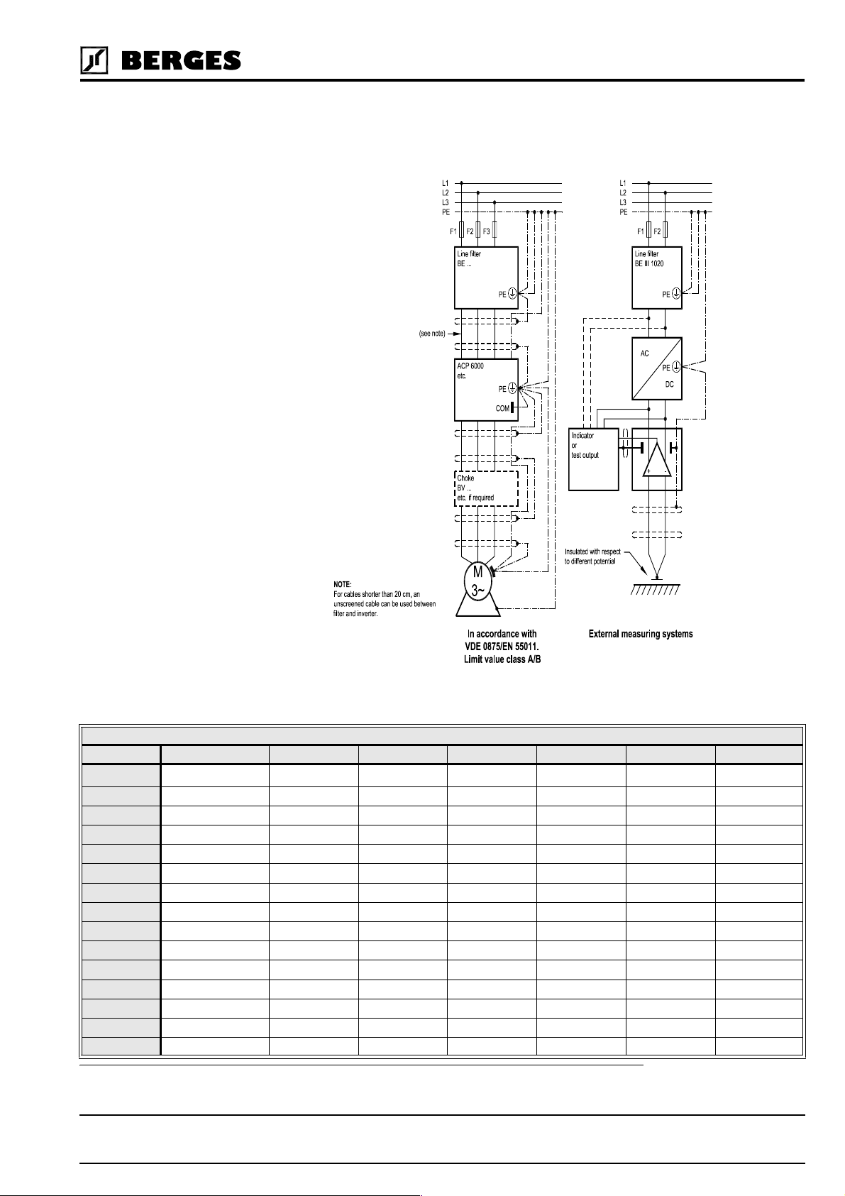
3.3.1 Suggestion on how to solve the Problem of Radio Frequency Interference
Suppression of Frequency Converters to VDE 0875/EN 55011
It is necessary to connect a mains filter type “BE/(xxx) xxxx” before every frequency converter. The size (xxx) depends on the rated current of the unit. A motor choke can be dispensed with.
HINT!
The motor choke type BV... may be necessary as from a cable length in excess of 20 m and
when operating several motors in parallel on one frequency converter output. This choke
attenuates the capacitive earth leakage currents and considerably reduces wire-borne interference voltages.
12
Operating manual 21.12.98
ACP 3000 — 0.37–15.0 04_GB
Berges electronic • D–51709 Marienheide-Rodt • Tel. 02264/17-0 • Fax 02264/17126
The converter and accessories must be wired in accordance with the following schematic.
To render the remaining interference voltage at the PE conductor potential ineffective for
“external measurement systems”, the following proposed circuit will achieve successful results if applied consistently.
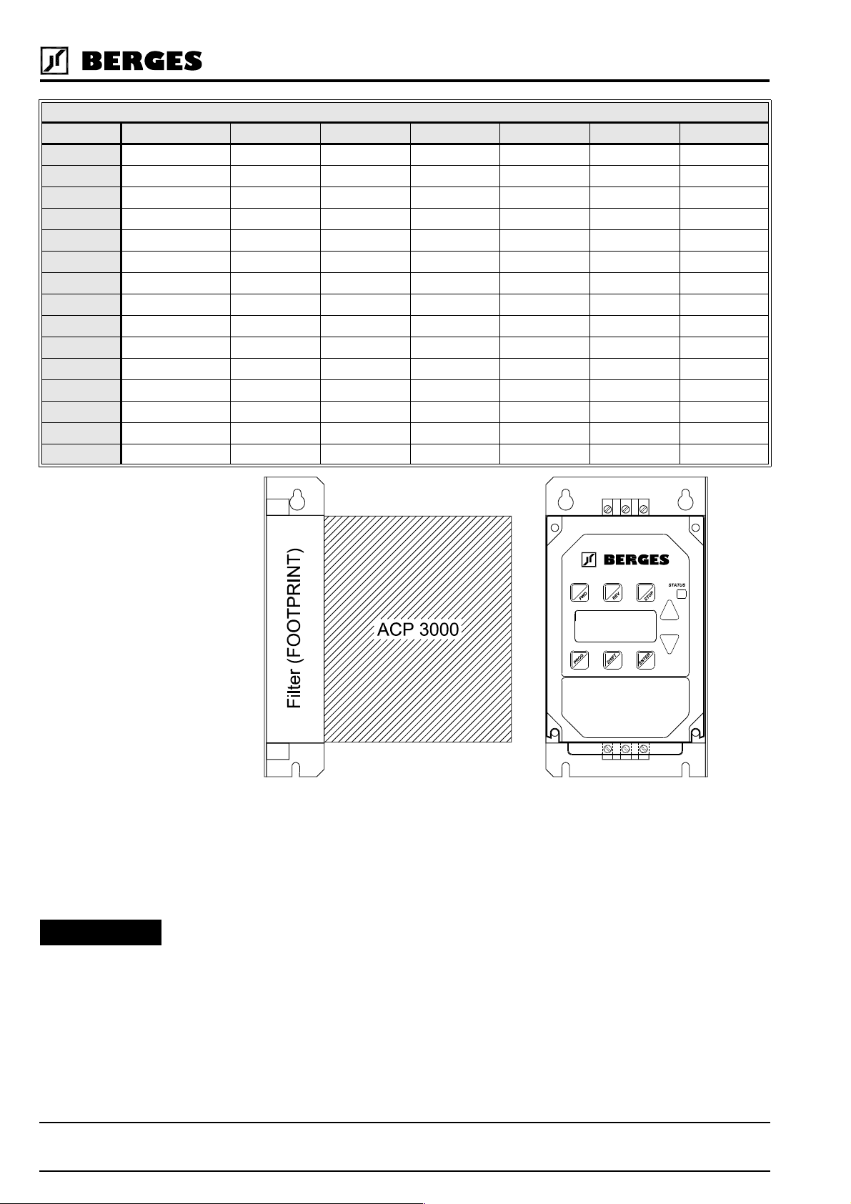
3.3.2 Mains Filters/Output Chokes
ACP 3000
DEVICE TYPE MAINS FILTER ARTICLE NO. INPUT PHASES VOLTAGE (V) CURRENT (A) WEIGHT (kg) FOOTPRINT
ACP 3300-3 BE I 1005 32501739 1~ 250 5 0.60
ACP 3300-5 BE I 1005 32501739 1~ 250 5 0.60
ACP 3300-7 BE II 1010 32501740 1~ 250 10 0.70
ACP 3301-1 BE II 1010 32501740 1~ 250 10 0.70
ACP 3301-5 BE III 1020 32501741 1~ 250 20 1.05
ACP 3302-2 BE III 1020 32501741 1~ 250 20 1.05
ACP 3600-7 BE I 3003 32501742 3~ 380/480 3 0.75
ACP 3601-5 BE II 3005 32501743 3~ 380/480 5 0.80
ACP 3602-2 BE III 3012 32501744 3~ 380/480 12 1.15
ACP 3603-0 BE III 3012 32501744 3~ 380/480 12 1.15
ACP 3604-0 BE III 3012 32501744 3~ 380/480 12 1.15
ACP 3605-5 BE IV 3038 32501745 3~ 380/480 38 1.90
ACP 3607-5 BE IV 3038 32501745 3~ 380/480 38 1.90
ACP 3611-0 BE IV 3038 32501745 3~ 380/480 38 1.90
ACP 3615-0 BE IV 3038 32501745 3~ 380/480 38 1.90
(1) FOOTPRINT means that these filters have been prepared for the installation of an ACP converter on the filter (securing).
(1)
(1)
(1)
(1)
(1)
(1)
(1)
(1)
(1)
(1)
(1)
(1)
(1)
(1)
(1)
21.12.98 Operating manual
04_GB ACP 3000 — 0.37–15.0
13
Berges electronic • D–51709 Marienheide-Rodt • Tel. 02264/17-0 • Fax 02264/17126
ACP 3000
DEVICE TYPE CHOKE ARTICLE NO. INPUT PHASES VOLTAGE (V) CURRENT (A) WEIGHT (kg) FOOTPRINT
ACP 3300-3 BV 20394/307 32501345 – 440 7 0.25 –
ACP 3300-5 BV 20394/307 32501345 – 440 7 0.25 –
ACP 3300-7 BV 20394/307 32501345 – 440 7 0.25 –
ACP 3301-1 BV 20394/307 32501345 – 440 7 0.25 –
ACP 3301-5 BV 20394/307 32501345 – 440 7 0.25 –
ACP 3302-2 BV 20394/313 32501346 – 440 13 0.70 –
ACP 3600-7 BV 20394/307 32501345 – 440 7 0.25 –
ACP 3601-5 BV 20394/307 32501345 – 440 7 0.25 –
ACP 3602-2 BV 20394/307 32501345 – 440 7 0.25 –
ACP 3603-0 BV 20394/307 32501345 – 440 7 0.25 –
ACP 3604-0 BV 20394/313 32501346 – 440 13 0.70 –
ACP 3605-5 BV 20394/313 32501346 – 440 13 0.70 –
ACP 3607-5 BV 20394/325 32501347 – 440 25 1.10 –
ACP 3611-0 BV 20394/325 32501347 – 440 25 1.10 –
ACP 3615-0 BV 20394/330 32501348 – 440 30 1.15 –
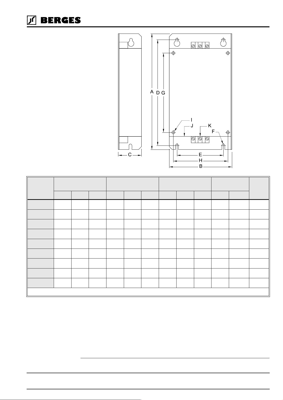
3.3.3 Filter Specifications
ATTENTION!
14
All BERGES line filters are provided in IP20 enclosures. They can operate over a temperature range of -10 to +50 °C (-23 to +122 °F). The filters can be mounted parallel or perpendicular to the control panel. The filter is supplied with the correct mounting hardware for
mounting the inverter on top of the filter enclosure (Footprint).
The mains filters and chokes must be installed and connected in conformity with the recommendations given in chapters 3.3.1 (page 12), 3.3.4 (page 15) and 3.6.3 (page 22).
Operating manual 21.12.98
ACP 3000 — 0.37–15.0 04_GB
Berges electronic • D–51709 Marienheide-Rodt • Tel. 02264/17-0 • Fax 02264/17126
TYPE OUTER DIMENSIONS SECURING SECURING ON THE
CONNECTIONS FOOT-
INVERTER
A B C D E F G H I J (PE) K
BE I 1005 200 108 40 183 80 M5 137 94 M5 M4
BE II 1010 200 145 40 183 110 M5 137 129 M5 M4
BE III 1020 250 145 45 235 110 M5 188 129 M5 M4
BE I 3003 200 108 40 183 80 M5 137 94 M5 M4
BE II 3005 200 145 40 183 110 M5 137 129 M5 M4
BE III 3012 250 145 45 235 110 M5 188 129 M5 M5
BE IV 3038 360 222 50 342 160 M6 280 200 M6 M5
BE V 3012 360 222 50 342 160 M6 280 200 M6 M5
BE VI 3040 496 232 50 478 180 M6 419 200 M6 M5
Table 3.2
NOTE: Dimensions in mm.
(1)
3.3.4 Interference Suppression Measures
2,5 mm
2,5 mm
2,5 mm
2,5 mm
2,5 mm
2,5 mm
16 mm
16 mm
16 mm
PRINT
2(1)
2(1)
2(1)
2(1)
2(1)
2(1)
2(1)
2(1)
2(1)
Electrical/electronic devices are capable of influencing or disturbing each other through
connecting cables or other metallic connections. “Electromagnetic compatibility” consists of
the factors “interference resistance” and “interference emission”. Correct installation of
the inverter in conjunction with any possible local interference suppression measures has a crucial effect on minimizing or suppressing mutual interference.
(1) FOOTPRINT means that these filters have been prepared for the installation of an ACP converter on the filter (securing).
21.12.98 Operating manual
04_GB ACP 3000 — 0.37–15.0
15
Berges electronic • D–51709 Marienheide-Rodt • Tel. 02264/17-0 • Fax 02264/17126
The scope of noise suppression measures depends on the limit value class, the local situation and the application.
The following notes refer to a mains power supply that is not “contaminated” by high frequency interference. Other measures may be necessary to reduce or suppress interference
if the mains voltage is “contaminated”. No generally valid recommendations can be given
in such cases. Please consult BERGES if all recommended interference suppression
measures should not produce the desired result.
Basically, it is not the cross section of the conductor that is important for radio-frequency
interference suppression but the surface area. Since the high-frequency interference does
not flow through the entire cross section but mainly on the outer surface of the conductor
(skin effect), braided copper tapes of corresponding cross section should be used.
All conductive housing parts must be interconnected using corresponding lines. Minimum
cross sections are prescribed for a fault case at 50 Hz (referred to the range of the safety
regulations) which must be observed under all circumstances.
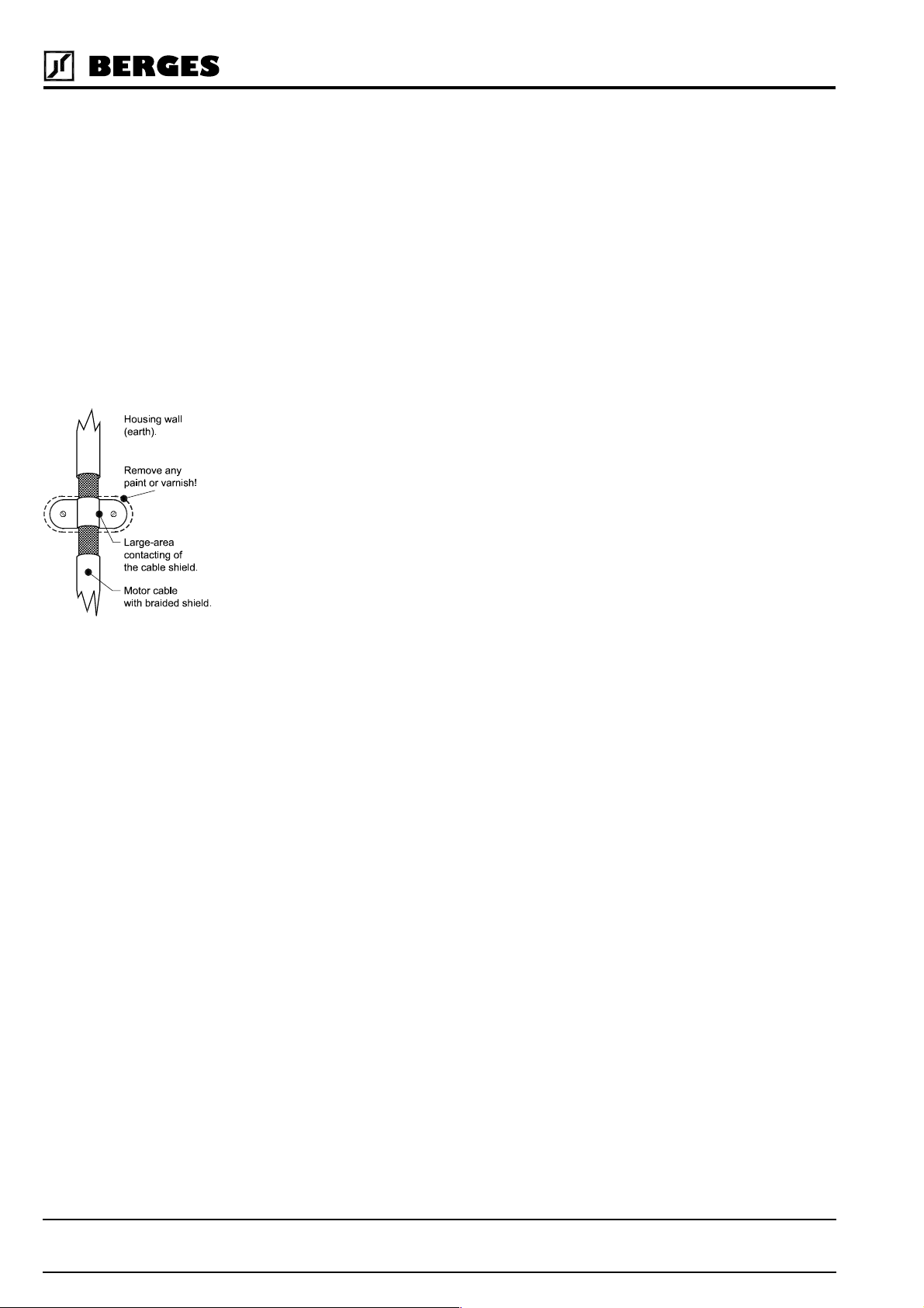
The inverter and all other components used for interference suppression (especially also
the shield of the motor cable) should be contacted over as large an area as possible when
connected to metal (control panels, switchgear cabinets and similar) (skin effect). Remove
the paint at the respective areas to ensure good contacting over a large area!
A central earthing point should be used for interference suppression (e.g. equipotential
bonding strip or centrally at an interference suppression filter). The earthing lines are routed
to the respective terminals radially from this point. Conductor loops of the earthing lines
are impermissible and can lead to unnecessary interference.
The shield cross section must not be reduced when the shield is connected to continuing
lines. This would give rise to RF resistance at a cross section reduction, and the resulting
RF energy would consequently not be discharged but radiated. Shields – particularly
shields of control lines – must not be contacted via pin contacts of plug connectors. In these
cases, the metallic hand guard of the plug connector should be used for large-area connection of the shield.
Use a shielded motor cable (earthed over a large area at both sides). The shield should be
routed uninterrupted from the PE terminal of the inverter to the PE terminal of the motor.
If a shielded motor line cannot be used, the unshielded motor line should be laid in a metal
duct. The metal duct must be uninterrupted and adequately earthed. The following points
are prescribed if radio interference suppression is to be realized in accordance with EN
55011, EN 55014 and EN 50081-1:
• Preceding the unit by a mains filter or a mains filter and a output choke (mains filter and
output choke not included in the scope of delivery).
• Laying the motor cable in a shielded configuration.
• Laying the control cable in a shielded configuration.
• Observe general RFI suppression measures (refer to the chapters 3.3.1 and 3.3.4).
Lay motor, mains power and signal cables as far away from each other as possible and separately.
If a mains filter is used, the smallest possible spatial distance from the frequency inverter
must be selected so that both units can be connected by short connection leads.
If an output choke is used (option), it must be fitted in the direct vicinity of the inverter and
connected to the inverter via screened cables earthed at both ends.
16
Shielded signal cables should be laid at a minimum distance of 10 cm from power cables
running parallel. A separate earthed metal cable duct is advisable for such signal cables. If
signal cables intercept with a power cable, they should do so at an angle of 90°.
Operating manual 21.12.98
ACP 3000 — 0.37–15.0 04_GB

Berges electronic • D–51709 Marienheide-Rodt • Tel. 02264/17-0 • Fax 02264/17126
Control lines longer than 1 m must be laid with a shield and earthed at one side on the frequency inverter. The screen is earthed via terminal “CM” in the case of pull-up logic and
pull-down logic (see “Connection Diagrams”, chapters 7.1 to 7.7). If cables have lengths in
excess of 10 m, use a 0–20 mA control signal because of the possibility of parasitics. The
inverter can be switched over to this mode of operation. See parameter
5.2, page 38).
Other loads connected to the mains may produce voltage spikes that may interfere with
functioning of the inverter or may even damage it. Chokes or mains filters can be used on
the mains side to protect the inverter against voltage spikes (resulting from switching large
loads to the mains). Such chokes and filters are available as accessories.
If inverters are operated in switchgear devices or in their close proximity (e.g. in one common control cabinet) in connection with the same power mains, we recommend the following precautionary measures to suppress interference in the switchgear:
• Wire the coils of contactors, switchgear devices and relay combinations with “RC elements” or with free-wheel diodes.
• Use shielded cables for external control and measuring cables.
• Lay disturbing cables (e.g. power and contactor control circuits) separately and at a distance from the control cables.
3.4 EMC Ordinance (EMC Directive, 89/336 EEC)
24-FSEL
(chapter
HINT!
The frequency inverters were tested in the form of a practical test set-up in a switchgear
cabinet (in accordance with our interference suppression measures in these operating instructions: “EMC (electromagnetic compatibility)”. The limit values of the standards below
were fulfilled under these conditions:
EMA (Electromagnetic Emission)
EN 50081-1 Basic specification “Emitted interference” (Limit value class A)
or
EN 50081-2 Basic specification “Emitted interference” (Limit value class B)
EN 55011 Emitted interference
EMB (Electromagnetic Interference)
EN 50082-2 Basic specification “Interference immunity”
EN 50140 Electromagnetic fields
EN 60801 Static discharge (ESD)
IEC 801-4 Burst on mains lead/data line
At least the following conditions must be fulfilled for compliance with
the limit values of the aforementioned standards:
• Installation of a mains filter or a mains filter and a motor choke (mains filter and motor
choke are not included in the scope of delivery).
• Laying the motor cable in a shielded configuration.
• Laying the control cable in a shielded configuration.
• Observe general RFI suppression measures (refer to the chapters 3.3.1 and 3.3.4).
As the aforementioned interference resistance tests are based on standardised mains conditions, in extreme cases it may happen that the function of the inverter will be lost (minimum operating quality). This malfunction can generally be remedied by a RESET of the
inverter. Refer to the chapter entitled “Resetting a Fault” and “Fault Codes” on page 63.
Detailed information and technical data relating to adapted mains filters and chokes can be
found in the chapters 3.3.2, “Mains Filters/Output Chokes” and 3.3.3, “Filter Specifications”.
21.12.98 Operating manual
04_GB ACP 3000 — 0.37–15.0
17

Berges electronic • D–51709 Marienheide-Rodt • Tel. 02264/17-0 • Fax 02264/17126
3.5 Wiring Practices
3.5.1 Applicable Codes
Pay conscientious attention to ensuring that the installation wiring is installed at least in conformity with the NEC standards. Where local codes exceed these requirements, they must
be followed.
All models are listed by the Underwriters Laboratories, Inc. (UL) and are certified by the Canadian Underwriters Laboratories (cUL) and therefore conform to the requirements of NEC
and CEC. Installations that are to meet the requirements of UL and cUL must be realised
in conformity with the UL and cUL specifications. Refer to the corresponding electrical data
on the rating plates of the ACP 3000 unit and the motor.
3.5.2 Power Wiring
Power wiring are those wires which are connected during installation to the power circuit
terminals, L1, N, L2, L3, M1, M2, and M3. Power wiring must be selected as follows:
1. Use only VDE, UL or cUL recognized wire.
2. Wire voltage rating must be a minimum of 300 V for 230 VAC systems, and 600 V for
400 VAC systems.
ATTENTION!
3.5.3 Control Wiring/Interface
ATTENTION!
3. The core cross section and the associated fuse are given in the tables in chapter 3.6.2,
page 22. The wires must consist of copper and be designed for insulation temperatures
of 60 °C or 75 °C.
4. Grounding must be in accordance with VDE, NEC and CEC.
NOTES:
Never connect input AC power to the motor output terminals M1, M2 and M3 or dam-
age to the drive will result.
The output voltage of variable-frequency controllers contains high-frequency components
that might cause disturbances in other installations. Therefore, avoid laying control cables
and mains input cables in the same cable duct or conduit together with the output cables
from the converter to the motor (see also chapter 3.3.4, “Interference Suppression Measures”).
All interfaces or control inputs and outputs possess only basic insulation by the
mains and must be incorporated in a further protective measure.
Use a dummy plug as additional protection if interface J22 is not allocated.
This is wiring connected to the control terminal strip (20 terminals). It must be selected as
follows:
1. Shielded wire is recommended to prevent electrical noise interference from causing improper operation or nuisance tripping. Only connect the screen on one end to the “CM”
terminal on the converter’s control terminal strip (see also chapter 3.3.4, “Interference
Suppression Measures”).
18
2. Use only VDE, UL or cUL recognized wire.
3. Wire voltage rating must be a minimum of 300 V for 230 VAC systems, and 600 V for
400 VAC systems. This is Class 1 wire.
4. Never run the control wiring in the same conduit or raceway with power wiring.
Operating manual 21.12.98
ACP 3000 — 0.37–15.0 04_GB
Berges electronic • D–51709 Marienheide-Rodt • Tel. 02264/17-0 • Fax 02264/17126
5. Do not use wire end ferrules for the control terminals. The terminals are designed
so that the wires can be inserted in the terminals after twisting the individual
wires.
3.6 Mains Power Connection
The frequency inverters are designed for installation in a switchgear cabinet and for
permanent connection.
To guarantee lasting operating safety and reliability, the inverter must be connected expertly in accordance with the valid electrical standards. Attention must be paid to good insulation from earth potential on the power terminals.
An AC system with a nominal voltage of 230 V (50/60 Hz) must be connected to mains terminals L1, N and PE or a three-phase system with a nominal voltage of 400 V (50/60 Hz)
to terminals L1, L2, L3 and PE (pay attention to rating plate). The neutral point must be
earthed (TN-C system).
Ensure a voltage balanced to earth or phase to phase when feeding in the mains power
through an isolating transformer (star point must be earthed).
Frequency inverters must not be connected via a residual-current-
operated circuit-breaker as the sole protective measure!
The single exception below permits connection of a frequency inverter via a residual-current-operated circuit-breaker as the sole protective measure:
• Installation of a residual-current-operated circuit-breaker of the newest design for fre-
quency inverters up to 4 kVA (input voltage 1 × 230 V) with MOBILE connection.
This residual current-operated circuit breaker must be suitable for alternating and pulsating DC leakage current. Residual-current-operated circuit-breakers of this type bear
the symbol .
Reliable tripping of the residual-current-operated circuit-breaker is not ensured in
the case of frequency inverters up to 4 kVA (input voltage 3 × 400 V) with MOBILE
connection; an additional protective measure must be used for this reason. Also see
the diagram below.
In the case of frequency inverters with PERMANENT connection (input voltage 1 ×
230 V and 3 × 400 V), another protective measure must always be used in addition to
the residual-current-operated protective device. Also see the diagram below.
The protective function of the residual-current-operated circuit-breaker is no longer ensured
due to leakage currents from interference suppression capacitors in the inverter and DC
components in the fault current. All devices connected to this residual-current-operated circuit-breaker (and persons touching them) are no longer protected in the event of a fault.
21.12.98 Operating manual
04_GB ACP 3000 — 0.37–15.0
19

Berges electronic • D–51709 Marienheide-Rodt • Tel. 02264/17-0 • Fax 02264/17126
Flow diagram of the requirements relating to the combination of frequency inverter
and residual-current-operated protective device
The inverter will be destroyed if the mains feeder is confused with the motor cable.
The DC link capacitors must be reformed if the inverter you wish to connect has been out
of operation for more than a year. To do this, connect the inverter to voltage for approx. 30
minutes. The inverter should not be loaded by connected motors during forming.
3.6.1 Mains Conditions
Permissible fluctuation of the mains voltage amounts to around ±10% of the rated
voltage. If the mains voltage should exceed or fall below these limits, the inverter will
be deactivated automatically as the result of the undervoltage or overvoltage.
When applying the inverter to line voltages other than the factory default values (230 VAC
or 460 VAC), be sure to set parameter
Adaptation to rated line voltages outside the permissible range is possible by means of autotransformers. Calculation according to the formula below is recommend:
U
P
T
P
D
NOTE:
Exercise caution when using the ACP 3000 under the conditions of a low-voltage network.
An inverter from the ACP 3000 series is fully functional when connected to an alternating
current of 370 V, for example. However, the maximum output voltage is limited to 370 VAC.
If the motor is rated for a mains voltage of 400 VAC, this can lead to higher motor currents
and overheating of the motor. It must be ensured that the connected mains voltage cor-
responds to the rated voltage of the motor.
PD 1
=
U2I2× 3×=
------ -–
U
59-MVOLT
P
2
1
= Equivalent two-winding kVA rating (kVA)
T
P
= Continuous output (kVA)
D
= Rated line voltage (V)
U
1
U
= Rated voltage, frequency inverter (V)
2
= Input current (A) as per table 2.1 and 2.2
I
2
to the proper value. Refer to page 42.
20
If other than 50 Hz output can be tolerated, proper volts/hertz can be programmed into the
inverter by the
53-FKNEE
and
32-FMAX
parameters. If you are unsure about this feature,
consult section 5.2 or BERGES.
Phase voltage imbalance of the input AC source can cause unbalanced currents and ex-
cessive heat in the input rectifier diodes and in the DC bus capacitors of the ACP. Phase
imbalance is calculated by the following method:
Operating manual 21.12.98
ACP 3000 — 0.37–15.0 04_GB

Berges electronic • D–51709 Marienheide-Rodt • Tel. 02264/17-0 • Fax 02264/17126
Assume:
The voltage from L1 to L2 = L
The voltage from L2 to L3 = L
The voltage from L3 to L1 = L
The average line voltage = L
LaLbL
L
avg
++
------------------------------ -
c
3
a
b
c
avg
395 400 405++
------------------------------------------ 400== =
3
ATTENTION!
3.6.2 Line Protection
Determine the absolute value of the difference between each of the line voltages (La, L
and Lc) and L
the results of this calculation to be L
Phase Imbalance
. (Subtract the two values and disregard the sign of the result.) Consider
avg
, Lba, and Lca.
aa
++
L
aaLbaLca
--------------------------------------- -
()
2 L
avg
100%×
505++
----------------------
2 400×
100%× 1.25%===
Example: Measured phase voltages of 395, 400, and 405 would result in a calculated
phase imbalance of 1.25%.
If the resulting phase imbalance exceeds 2%, consult your local power company or plant
maintenance personnel and ask them to investigate this problem and recommend methods
of correcting this condition.
Phase imbalance can also cause damage to motors running direct on line. A 2% imbalance
requires a 5% derating factor on the motor, 3% imbalance requires a 10% derating. 4% requires an 18% derating.
NEVER USE POWER-FACTOR IMPROVEMENT CAPACITORS ON THE ACP MOTOR
TERMINALS, M1, M2, AND M3, OR DAMAGE TO THE INVERTER'S SEMICONDUCTORS WILL RESULT!
It is necessary to provide either a circuit breaker or a fused disconnect switch on the input
AC line in accordance with all applicable electrical codes. The following rules should be
used to select the correct size of the input line fuses or circuit breaker.
b
A. Sizing
The ACP inverter is able to withstand a 150% overload for 60 seconds. Minimum voltage
rating for the protection device should be 250 VAC for models 3300-3 to 3302-2, and 600
VAC for models 3600-7 to 3615-0.
B. Fuse Type
To guarantee a maximum protection of the inverter fuses should be used for current Limitation. These fuses should have a breaking capacity of 200,000 A
shows the recommended values in amps for all ACP-inverters.
ATTENTION!
21.12.98 Operating manual
04_GB ACP 3000 — 0.37–15.0
For 230/400 V mains supplies we recommend time-lag type NEOZED-fuses.
. The following tables
eff
21

Berges electronic • D–51709 Marienheide-Rodt • Tel. 02264/17-0 • Fax 02264/17126
SUPPLY VOLTAGE 1 × 230 VAC
Type 3300-3 3300-5 3300-7 3301-1 3301-5 3302-2
Inverter power (kW) 0.37 0.55 0.75 1.1 1.5 2.2
Rated current, fuse (A) 4 6 6 10 10 16
Cable cross section, mains lead (mm2)
Cable cross section, motor lead (mm2)
Type 3600-7 3601-5 3602-2 3603-0 3604-0 3605-5 3607-5 3611-0 3615-0
Inverter power (kW) 0.75 1.5 2.2 3.0 4.0 5.5 7.5 11.0 15.0
Rated current, fuse (A) 2 4 6 6 10 16 16 25 32
Cable cross section, mains lead (mm2)
Cable cross section, motor lead (mm2)
For mains supplies with rated voltage exceeding 415 V the semi-lag fuses type “Bussmann
FRS-R” are recommended. The typical disconnection times are 150–250 sec. for 2 times
the overcurrent and 180–1500 msec. for 10 times the overcurrent.
1.5 1.5 1.5 1.5 1.5 2.5
1.5 1.5 1.5 1.5 1.5 1.5
SUPPLY VOLTAGE 3 × 400 VAC
1.5 1.5 1.5 1.5 1.5 2.5 2.5 4 6
1.5 1.5 1.5 1.5 1.5 1.5 2.5 4 6
3.6.3 Using Mains Filters
Special protective measures must be observed when using mains filters:
Owing to the leakage current involved (>3.5 mA), attention must be paid to EN 50178 when
using BERGES mains filters. One of the following protective measures must be taken:
ATTENTION!
• The mains filter must be connected separately by laying a second cable that is electrically parallel with the PE conductor; this conductor must meet the requirements of IEC
364-5-543 on its own.
2
• The PE conductor must have a cross section of at least 10 mm
diagrams).
• The PE conductor must be monitored by a facility that isolates the inverter from the
mains in the event of a fault (PE conductor monitoring).
The inverter must always be connected permanently (EN 50178) when using mains
filters (leakage current >3.5 mA).
Mains filter connection with a second
parallel PE conductor
Mains filter connection with at least
2
10 mm
PE conductor cross section
(refer to the following
22
Operating manual 21.12.98
ACP 3000 — 0.37–15.0 04_GB

Berges electronic • D–51709 Marienheide-Rodt • Tel. 02264/17-0 • Fax 02264/17126
3.6.4 Line Starting
ACP 3000 is designed to provide controlled starting and stopping of AC motors by use of
the keypad or external contacts connected to the control terminal strip. The drive may also
be started by using a maintained contact (2-wire operation). To prevent accidental starting
of the motor, the inverter has linestart-lockout as a standard feature. This provision can be
defeated by programming
The inverter may be started once every two (2) minutes in this mode.
3.7 Motor Connection
Connect the motor cable to the “M1, M2, M3” and “PE” terminals.
The inverter will be deactivated if shorted to the motor terminals.
82-START
(see page 48).
ATTENTION!
The output of the drive will always be three phase. Do not connect single-phase motors to the inverter output terminals M1, M2 or M3.
Never use power factor correction capacitors on the motor terminals M1, M2 and M3,
or damage to the semi-conductors will result.
We recommend PTC evaluation using commercially available devices to achieve effective
protection of the motor.
If interrupting contacts (e.g. contactors or motor protection switches etc.) have to be installed between the motor and inverter, the circuit must be configured so as to ensure that
the “Enable” signal (terminals V+ and FWD/REV by pull-up logic, terminals CM and FWD/
REV by pull-down logic) is deactivated before separation of the inverter/motor connection.
A relay switching time of approx. 30 ms suffices.
In the case of special motors, the corresponding Volt/Hz values can be programmed on the
inverter by means of the parameters
contact BERGES or refer to chapters 5.2 and 9.1.
53-FKNEE
3.8 Reducing Current Surges and Voltage Transients
Voltage spikes caused by coils (inductors operated on the same mains as the inverter) can
lead to malfunctions of the inverter. In cases of this kind, the affected windings of contactors
and relays operated on the 230 VAC mains must be damped by fuses in the form of an RC
series circuit:
• Main Circuit Contactors and Solenoids: C = 0.2 MFD, 500 VDC; R = 500 W, 5 Watts.
• Auxiliary Control Circuit Relays: C = 0.1 MFD, 500 VDC; R = 200 W, 2 Watts.
and
32-FMAX
. In cases of doubt, please
Connection Diagram for AC and DC Relay Coils and Solenoids:
Figure 3.2
21.12.98 Operating manual
04_GB ACP 3000 — 0.37–15.0
23

Berges electronic • D–51709 Marienheide-Rodt • Tel. 02264/17-0 • Fax 02264/17126
Free-wheeling diodes must be used on contactors, relays and solenoid coils operated with
direct current. The diodes in question should be fast types with short recovery time. The
diode must be connected in blocking direction in parallel with the winding (see Figure 3.2).
The rated current and voltage of the diode can be calculated using the formulae below:
Diode Current Rating (A)
Diode Voltage Rating (V) Rated Voltage of Coil (V) 2×≥
≥
3.9 Function and Use of Terminals
Refer to section 7.1 to 7.7 – Connection Diagrams for power and control wiring examples.
A. Power Circuit Terminals
Power terminals are located on the power module of the ACP 3000 inverter. They are labelled L1, L2, and L3 for incoming three phase AC line power (L1 and N for incoming singlephase AC line power), and M1, M2, and M3 for the motor connections.
Two ground connections (GND) are provided on the end plate of 0.37 to 4.0 kW IP 21 models (see Figures 3.4 and 3.5), and along the power terminal strip of 5.5 to 15.0 kW IP 21
models (Figure 3.6). Ground connections can be made to the heat sink on chassis models.
The ground screws must be connected to earth ground in accordance with the NEC.
Coil Capacity (VA)
------------------------------------------------------------------
Rated Voltage of Coil (V)
5.5 to 15.0 kW inverters also have two terminals, B+ and B-, that provide access to the DC
bus rails for the addition of external dynamic braking kits, or extra bus capacitors for custom
applications.
B. Control Terminals
The control terminals are located on the bottom edge of the inverter's control board. See
Figures 3.4 to 3.6, page 26/27 and chapter 3.15. These terminals are available for use with
external devices.
The 20-pole control terminal strip of the units, 0.37–4.0 kW, is plugged in and can be removed in the upward direction to connect the control cables. To do this, place a flat screwdriver on the metal tabs of the cover securing element and carefully lever off the terminal
strip in the upward direction.
NOTE:
Control input signals must not exceed 24 VDC ±20% potential to ground.
Logic Input Levels:
LOGIC TYPE PULL-UP PULL-DOWN
Active 10–24 VDC 0–3 VDC
Inactive 0–3 VDC 10–24 VDC
The input logic is compatible with either 12 or 24 VDC logic. J20 selects active High or Low
control inputs.
24
Operating manual 21.12.98
ACP 3000 — 0.37–15.0 04_GB

Berges electronic • D–51709 Marienheide-Rodt • Tel. 02264/17-0 • Fax 02264/17126
3.10 Terminal Access Cover Removal Hazard of electrical shock.
Disconnect power before working on this drive.
Dangerous voltages exist until the STATUS Indicator is off.
A. IP 21 Enclosures
IP 21 versions of the ACP 3000 inverter are designed to prevent accidental removal of the
terminal access cover. The cover mounting meets UL and NEC specifications for safety.
To remove the access cover from 0.37 to 4.0 kW inverters, loosen the two screws mounted
at the lower corners of the cover (see Figure 3.3). When replacing the cover, a snug fit only
is required. Do not torque the screws or damage to the cover may result.
To remove the access cover from 5.5 to 15.0 kW inverters, insert a small blade screwdriver
into the slots located on the lower left and right corners of the cover. Use a slight twisting
motion while lifting upward to loosen one side then the other, and then lift the cover off the
inverter. To replace, hook the cover onto the two retainers on top of the inverter base and
snap the cover into place.
Figure 3.3
Access Cover
Access Cover
Mounting Screw
(Not Shown)
Conduit Entry
Plate
Access Cover
Mounting Screws (2)
21.12.98 Operating manual
04_GB ACP 3000 — 0.37–15.0
25

Berges electronic • D–51709 Marienheide-Rodt • Tel. 02264/17-0 • Fax 02264/17126
3.11 Terminal Assignment (Mains supply 1 × 230 VAC, 0.37–4.0 kW)
CM
MET2
MET1
CM
VIN2
VIN1
REF
CM
FWD
REV
PS3
PS2
PS1
V+
V+
MOL
ST1
NO
RCM
NC
J20
L1
AC Line
L1, N
Motor
N
M1 M2 M3
Control
Terminals
J22
M1, M2, M3
Figure 3.4
(1)
3.12 Terminal Assignment (Mains supply 3 × 400 VAC, 0.37–4.0 kW)
V+
V+
CM
MET2
MET1
CM
VIN2
VIN1
REF
CM
FWD
REV
PS3
PS2
PS1
MOL
ST1
NO
RCM
NC
26
J20
L1
AC Line
L1, L2, L3
Motor
L2 L3
M1 M2 M3
Control
Terminals
J22
M1, M2, M3
Figure 3.5
(1) Power Terminals torque to 3.4 Nm max.
Control Terminals torque to 0.28 Nm max.
(1)
Operating manual 21.12.98
ACP 3000 — 0.37–15.0 04_GB

Berges electronic • D–51709 Marienheide-Rodt • Tel. 02264/17-0 • Fax 02264/17126
3.13 Terminal Assignment (Mains supply 3 × 400 VAC, 5.5–15.0 kW)
J20
Control Terminals
CM
MET2
MET1
CM
VIN2
B- B+ GND GND L3 M1 M2 M3L1 L2
AC Line
L1, L2, L3
Figure 3.6
FWD
REV
CM
VIN1
REF
Motor
M1, M2, M3
(1)
PS3
PS2
PS1
J22
NO
MOL
V+
RCM
ST1
NC
V+
(1) Power Terminals torque to 3.4 Nm max.
Control Terminals torque to 0.28 Nm max.
3.14 Remote Keypad/Program Memory Unit Connector (J22)
Connector J22, located on the right side of the ACP 3000 micro-inverter, is used with either
the Remote Keypad Unit (XRK01) or Program Memory Unit (XPM01), both sold separately.
Both options are battery or AC line adapter powered and can be used with any ACP 3000
model to allow remote programming and control of the inverter. The Remote Keypad Unit
can be mounted on another enclosure up to 100 m from the inverter. Programmer options
allow storage of up to ten separate parameter sets.
3.15 Control Terminal Description
The ACP 3000 series micro-inverter has a 20 position control terminal block. Some functions are defined by the setting of jumper J20, while others are defined by programming.
Refer to section 7.1 to 7.7 and Figures 3.4 to 3.6.
DESCRIPTION OF TERMINALS
CM Circuit Common, isolated from ground.
MET1 Analog meter output 1. Provides a 0 to 10 VDC (1 mA maximum) signal proportional to output frequency,
load, or current through setting of
70-MCAL
(page 45). Output impedance is 475 Ω.
MET2 Analog meter output 2. Provides a 0 to 20 mA or 4–20 mA signal proportional to output frequency, load, or
current through setting of
79-MET2
(page 47). Output impedance is 10 Ω.
71-METER
. May be calibrated while inverter is running by programming
. May be calibrated while inverter is running by programming
78-MCAL2
21.12.98 Operating manual
04_GB ACP 3000 — 0.37–15.0
27

Berges electronic • D–51709 Marienheide-Rodt • Tel. 02264/17-0 • Fax 02264/17126
DESCRIPTION OF TERMINALS
VIN1 Analog speed input 1. Selectable through jumper J20 for 0–5 VDC, 0–10 VDC, or 0/4–20 mA DC. A 4 mA
offset is programmed by
selected, the reference value is the sum of the two analog inputs or, if
24-FSEL
. Only VIN1 is active with functions 0–4. If a function between 4 and 7
24-FSEL
has been programmed
accordingly (page 38), it is the difference between VIN1 and VIN2 (functions 8–11). Functions 12–15
switch between VIN1 and VIN2. VIN1/VIN2 changeover via PS3.
VIN2 Analog speed input 2. Selectable through jumper J20 for 0–5 VDC or 0–10 VDC. Only VIN1 is active with
functions 0–4. If a function between 4 and 7 selected, the reference value is the sum of the two analog inputs or, if
24-FSEL
has been programmed accordingly (page 38), it is the difference between VIN1 and
VIN2 (functions 8–11). Functions 12–15 switch between VIN1 and VIN2. VIN1/VIN2 changeover via PS3.
REF 5.2 VDC reference voltage, 3 mA maximum load. USE ONLY FOR A FREQUENCY CONTROL POTEN-
TIOMETER (5 kΩ recommend).
FWD Digital input for Forward operation. May be programmed for maintained (standard) or momentary contacts
21-MODE
by
. See page 36.
REV Digital input for Reverse operation. May be programmed for maintained (standard) or momentary contacts
by
21-MODE
. See page 36.
V+ Positive nominal 12 VDC voltage. Only for use with digital inputs (see pages 59 to 61). NO OTHER USE IS
ALLOWED.
MOL Motor Overload relay input. May be configured to generate a fault on opening or closing. May also be con-
PS1
PS2
PS3
figured to command a Coast-to-Stop on opening or closing. See page 47,
77-MOL
Digital inputs normally used for preset speed selection. Jumper J20 selects pull-up or pull-down logic (see
page 29). PS3 can be defined as a Run/Jog selector or VIN1/VIN2 switch by
as the ART selector by
41-RSEL
(see page 39), unless the PI Regulator is enabled and PS3 is used as an
.
21-MODE
(see page 36), or
ON/OFF switch. Eight preset speeds are available if all 3 inputs are used, and four are available if PS3 is
redefined via
21-MODE
or
41-RSEL
.
PS1 PS2 PS3 Effective Speed Reference
0 0 0 Basic speed setpoint (keypad or terminals)
100 33-F2
010 34-F3
110 35-F4
001 36-F5
101 37-F6
011 38-F7
111 32-FMAX
PS1 PS2 PS3 Effective Speed Reference
PS1
PS2
(1)
0 0 N/A Basic speed setpoint (keypad or terminals)
10N/A 33-F2
01N/A 34-F3
11N/A 35-F4
ST1 Digital output (open collector transistor). May be set to activate under one of ten conditions. See
72-ST1
(page 46). Maximal load: 24 VDC, 50 mA.
NO Normally open contact for the Auxiliary Relay. Will close when the relay is activated. Rating is 115/240 VAC
at 1 Ampere.
RCM Auxiliary relay common terminal. May release by appropriate adjustment at one of ten preset conditions.
See page 46,
75-STR
.
NC Normally closed contact for the Auxiliary Relay. Will open when the relay is activated. Rating is 115/240
VAC at 1 Ampere.
Table 3.3
28
(1) These settings will be utilized when PS3 is redefined via parameter
PS3 is used as an ON/OFF switch.
Operating manual 21.12.98
ACP 3000 — 0.37–15.0 04_GB
21-MODE
or
41-RSEL
, or when the PI Regulator is enabled and

Berges electronic • D–51709 Marienheide-Rodt • Tel. 02264/17-0 • Fax 02264/17126
3.16 J20 Configuration
Jumpers J20, on the bottom left edge of the control module (see Figures 3.4–3.6), enable
changeover of analog value specification and the switching logic of the digital control inputs.
It has seven (7) positions and two movable shorting jumpers. One jumper selects the analog speed reference used and the second jumper selects the active state (High or Low) of
the digital inputs. A pair of small needle nose pliers will prove useful for moving these jumpers. REMOVE AC POWER AND WAIT FOR ALL INDICATORS TO GO OUT BEFORE
CHANGING THIS JUMPERS.
JUMPER
SETTINGS
FUNCTION DESCRIPTION
VIN1: 0–10 VDC Terminal input VIN1:
This configures the drive to accept an external 0–10 VDC speed reference sig-
24-FSEL
nal.
VIN1: 0–20 mA
or 4–20 mA
VIN1: 0–5 VDC Terminal input VIN1:
VIN2: 0–10 VDC Terminal input VIN2:
VIN2: 0–5 VDC Terminal input VIN2:
Pull-Down Logic This configures the digital inputs for pull-down logic. That is, active when con-
Terminal input VIN1:
This configures the drive for either a 0–20 mA or a 4–20 mA input from an external source. 0–20 mA or 4–20 mA is selected by
250 kΩ.
(DEFAULT SETTING) This configures the drive for an external 0–5 VDC signal,
or a speed potentiometer powered from the REF terminal on the control terminal
24-FSEL
strip.
This configures the drive to accept an external 0–10 VDC speed reference signal.
24-FSEL
This configures the drive for an external 0–5 VDC signal, or a speed potentiometer powered from the REF terminal on the control terminal strip.
lects direct or inverse operation. Input impedance is 48 kΩ.
nected to terminal CM. Inputs are high, and are pulled low to activate.
selects direct or inverse operation. Input impedance is 95 kΩ.
24-FSEL
selects direct or inverse operation. Input impedance is 48 kΩ.
selects direct or inverse operation. Input impedance is 95 kΩ.
. Input impedance is
24-FSEL
se-
Pull-Up Logic (DEFAULT SETTING)
This configures the digital inputs for pull-up logic. That is, active when connected
to terminal V+, or to an external power supply with it's common connected to CM.
Inputs are low and require a positive voltage to activate them. 0 to 3 VDC is INACTIVE, 10 to 24 VDC is ACTIVE.
21.12.98 Operating manual
04_GB ACP 3000 — 0.37–15.0
29

4 Getting Started
4.1 General Information
Some ACP 3000 Series micro-inverters do not have a digital keypad as standard equipment. These models are programmed to operate via the control terminal strip. Use either
option XRK01 (Remote Keypad Unit) or XPM01 (Program Memory Unit) to re-program the
inverter.
Your ACP 3000 micro-inverter is pre-programmed to run a standard 4-pole AC induction
motor; in many cases no additional programming is required.
The advanced digital keypad controls all operations of the inverter. The eight input keys allow “Press and Run” operation of the motor and straight forward programming of the parameters. To simplify the programming further, the parameters are separated into two
Program Levels:
LEVEL 1 Easily entered by pressing the PROG key at any time. Limits access to the
LEVEL 2 Accesses all parameters including those in Level 1. Used when the more ad-
Berges electronic • D–51709 Marienheide-Rodt • Tel. 02264/17-0 • Fax 02264/17126
most commonly used parameters for operator convenience.
vanced features are needed. It is entered by pressing and holding the SHIFT
key then pressing the PROG key.
Parameters may be only be programmed when the drive is stopped, with the exception of
70-MCAL
4.2 Digital Keypad
and
78-MCAL2
which may be programmed at any time (see section 5.2).
Figure 4.1
30
4.3 Keypad Operation
When
21-MODE
keypad. The keys are used to operate the inverter as described in section 4.4.
is set to 0 or 10, start/stop and speed commands are accepted from the
Operating manual 21.12.98
ACP 3000 — 0.37–15.0 04_GB

Berges electronic • D–51709 Marienheide-Rodt • Tel. 02264/17-0 • Fax 02264/17126
4.4 Operation Mode (RUN and STOP Modes)
KEY FUNCTION
Initiates forward run when pressed momentarily. If the drive is running in reverse when FWD is pressed, it
will decelerate to zero speed, change direction, and accelerate to the set speed.
Initiates reverse run when pressed momentarily. If the drive is running in forward when REV is pressed, it
will decelerate to zero speed, change direction, and accelerate to the set speed.
Causes Ramp-To-Stop. Programmable to Coast-To-Stop by
In the Stop mode, pressing this key increases the desired running speed of the drive. In the Run mode,
pressing this key increases the actual running speed of the drive. Setting resolution is 0.05 Hz up to 99.95
Hz and 0.1 Hz above this frequency. The display will scroll at an increased rate after holding the key for
five seconds. Pressing SHIFT while holding the UP Arrow bypasses the delay.
In the Stop mode, pressing this key decreases the desired running speed of the drive. In the Run mode,
pressing this key decreases the actual running speed of the drive. Setting resolution is 0.05 Hz up to 99.95
Hz and 0.1 Hz above this frequency. The display will scroll at an increased rate after holding the key for
five seconds. Pressing SHIFT while holding the DOWN Arrow bypasses the delay.
In the Stop or Run modes, pressing this key will store the selected frequency as the initial operating frequency when the inverter is powered up. The frequency is maintained until another frequency is entered.
When the inverter is running, pressing this key accesses the Level 1 parameters for viewing only. Holding
SHIFT and then pressing PROG accesses the Level 2 parameters for viewing. Any attempt to program
(other than
is allowed in both Level 1 and Level 2. See section 4.5, page 31.
70-MCAL
and
78-MCAL2
) results in a display that shows “– – – –”. In Stop mode, programming
Table 4.1
4.5 Program Mode
KEY FUNCTION
When in Stop mode, pressing this key will enter the Program mode at Level 1. Pressing the key at any time
while in the Program mode will return the unit to the Operation mode. Pressing and holding SHIFT while
pressing PROG will access Level 2. If an Access Code has been invoked, it must be entered to change
Data Code. See page 50,
In the Program mode, pressing this key will move forward through the successive parameters. If the PRG
indicator is flashing it increases the Data Code. The ENTER key must be pressed to store the Data Code.
87-ACODE
.
41-RSEL
.
In the Program mode, pressing this key will move backward through the successive parameter addresses.
If the PRG indicator is flashing it decreases the Data Code. The ENTER key must be pressed to store the
Data Code.
NOTE:
If the PRG indicator is flashing, momentarily pressing and releasing both the UP and DOWN arrows simultaneously will return the Data Code to factory defaults. Press ENTER to store the new code.
Pressing this key while a parameter is displayed will allow that parameter to have its Data Code changed
by use of the UP and DOWN arrow keys. The PRG indicator flashes to show that the parameter can be
programmed.
This key must be pressed after the Data Code has been changed to store the new code. The display will
show STOred for one second indicating that the Data Code has been entered into memory.
Table 4.2
21.12.98 Operating manual
04_GB ACP 3000 — 0.37–15.0
31

Berges electronic • D–51709 Marienheide-Rodt • Tel. 02264/17-0 • Fax 02264/17126
4.6 Status Indicator
The STATUS indicator consists of two LEDs, one green and one red located in the upper
right corner of the control board. They are visible through a lens in the upper right corner of
the keypad on IP 21 models. The following table defines the STATUS indicator state for the
various operating conditions of the inverter:
STATUS INDICATION OPERATING CONDITION
COLOUR DURATION
Green and Red Continuous Power on, restart (2 Seconds)
Red Continuous Stop, running in torque limit
Green Continuous Run
Green and Red Flashing Running in and out of torque limit
Red Flashing Fault condition, Emergency Stop, line start lock-out, or low-
Green Flashing Running in and out of an overvoltage or undervoltage con-
voltage
dition
Table 4.3
4.7 Description of Displays
The back-lit, LCD display provides information on drive operation and programming. The
four large 7-segment displays show drive output and programming data. The two smaller
digits are used to indicate parameter numbers in the Program mode. Special symbols and
displays provide further clarification of drive operation. Figure 4.2 shows all segments displayed. In normal operation only those segments that are active are displayed.
Table 4.4 lists the special annunciators and their meaning:
SYMBOL DESCRIPTION
FWD Forward direction commanded
Figure 4.2
32
REV Reverse direction commanded
PRG Continuous: Program mode selected.
Flashing: Data Code may be changed
SET Inverter is stopped, or is having the running frequency set
OV Inverter is in an overvoltage condition
UV Inverter is in an undervoltage condition
Operating manual 21.12.98
ACP 3000 — 0.37–15.0 04_GB

Berges electronic • D–51709 Marienheide-Rodt • Tel. 02264/17-0 • Fax 02264/17126
SYMBOL DESCRIPTION
LIM Inverter is running in torque limit
OC Continuous: Inverter has tripped due to an overcurrent condition.
Flashing: Inverter is in an overcurrent condition
TEMP Continuous: Inverter has tripped due to an overtemperature condition.
Flashing: Inverter is near an overtemperature condition
DB The standard Dynamic Brake circuit is active
rpm Revolutions per minute indication
Hz Frequency in Hertz
h Time in hours
s Time in seconds
A Output current indication in Amperes
V Output voltage indication in Volts
% Display is in percent of units
C Degrees centigrade
4.8 Programming Tips
Accessing Parameters
• When the PROG (or SHIFT-PROG) key is pressed after the application of power or a
fault reset,
• If a different parameter is accessed and the Program mode is exited, that parameter is
the first one displayed the next time Program mode is entered.
• The inverter remembers a different “last parameter accessed” for Levels 1 and 2.
• If no key is pressed for 10 minutes while in the Program mode, the drive will automatically revert back to the operating mode.
Changing Display Scroll Rate
Three scroll rates are used to speed data entry.
• If either the UP or DOWN arrow is pressed and held for five seconds, the scroll rate will
increase.
• If the SHIFT key is momentarily pressed while pressing one of the arrow keys, the five
second delay will be bypassed.
21-MODE
Table 4.4
will always be the first parameter displayed.
• If the SHIFT key is pressed a second time while pressing an arrow key the display will
scroll at the fastest rate.
Restoring Factory Settings
• Whenever a parameter Data Code is being changed (noted by PRG blinking) the original
factory setting for that parameter can be restored by pressing and releasing both the UP
and DOWN arrows simultaneously and then pressing the ENTER key.
• To restore all parameters to factory settings, or to recall a previously stored parameter
set, see page 48,
21.12.98 Operating manual
04_GB ACP 3000 — 0.37–15.0
81-PRGNO
.
33

Help
• For Application Assistance, call BERGES electronic at 02264/17-160, 02264/17-102
4.9 Quick Start
This section is for operators with simple applications who would like to get up and running
quickly and with a minimum amount of reading of the manual. Be sure to read sections 4.1
through 4.8 before proceeding. In many cases your ACP 3000 will perform perfectly without
making any changes to the factory settings.
A. Perform all procedures for installation as specified in section 3 – Installation.
B. Apply AC power to the input terminals. For about two seconds the display will show all
Berges electronic • D–51709 Marienheide-Rodt • Tel. 02264/17-0 • Fax 02264/17126
and 02264/17-109.
RE-VERIFY THAT THE PROPER VOLTAGE IS CONNECTED TO THE INVERTER
BEFORE APPLYING POWER. FAILURE TO DO THIS CAN RESULT IN PERSONAL
INJURY AND EQUIPMENT FAILURE!
segments active (see Figure 4.2). The STATUS indicator will then turn red (indicating a
Stop condition) and the display will change to:
Figure 4.3
C. The factory settings correspond to control via the analog input VIN1. Activate terminal
FWD or REV. The FWD and REV keys are thus ineffective. The display will e.g. change
to:
Figure 4.4
D. Control the VIN1 terminal with 0–5/10 V or 0/4–20 mA. When the display gets to 0.1 Hz,
the inverter will start to produce an output. The motor will already begin to run with a correspondingly low load. When the motor starts to turn, check the rotation. If the motor is
turning in the wrong direction, PRESS STOP, REMOVE AC POWER AND WAIT FOR
ALL INDICATORS TO GO OUT. After the STATUS indicator has gone out, reverse any
two of the motor leads at M1, M2 or M3.
E. The inverter is preset to run a standard 4-pole AC induction motor to a maximum speed
of 50.00 Hz with both Acceleration and Deceleration times set to 3.0 seconds. See section 9.1, “Parameter Code Summary” for a complete list of all factory settings.
34
Operating manual 21.12.98
ACP 3000 — 0.37–15.0 04_GB

Berges electronic • D–51709 Marienheide-Rodt • Tel. 02264/17-0 • Fax 02264/17126
5 Parameter Configuration and Description
Level 1 – Accesses only basic operator parameters.
Level 2 – Accesses all parameters including those in Level 1.
5.1 Programming
Refer to Figures 4.1 and 5.1. To change the default Data Code in a given parameter:
A. Press the STOP key to stop the inverter if running.
B. Press the PROGram key to enter Level 1 Program mode. To enter Level 2 press and
hold the SHIFT key and then the PROGram key. The PRG indicator will turn on.
C. Press the UP/DOWN arrow keys to access the desired parameter. The parameter
number will be displayed in the upper left corner of the digital display.
D. Press the SHIFT key to allow the Data Code to be changed. PRG will starts to blink.
E. Press the UP/DOWN arrows to select the new Data Code.
F. Press the ENTER key to store the new Data Code. The display shows STOred for one
second.
G. Press the PROGram key to exit the Program mode or the UP/DOWN arrows to select a
new parameter.
Figure 5.1
5.2 Parameter Descriptions
The following section contains functional descriptions of all parameters. The number in the
“LEVEL” column indicates the programming level in which access to the parameter in question is possible. Access to all parameters is possible in level 2 (also to parameter in level
1). A “V” means that this parameter only has a view function, while “P” stands for program-
mable.
PARAMETER DESCRIPTION UNIT LEVEL
02-RVLVL – Software Revision 2V
This parameter holds the identification code of the Read Only Memory.
03-IRAT – Inverter Rated Current [A] 2V
This defines the nominal output current of the inverter and serves as the 100% reference
for all current measurements. Continuous drive capacity is 1.1 times 03-IRAT. Your ACP
3000 inverter can provide 110% of this rating continuously without damage or tripping.
21.12.98 Operating manual
04_GB ACP 3000 — 0.37–15.0
35

Berges electronic • D–51709 Marienheide-Rodt • Tel. 02264/17-0 • Fax 02264/17126
MODEL
NUMBER
3300-3 2.0 A 3602-2 5.5 A
3300-5 3.6 A 3603-0 9.0 A
3300-7 6.8 A 3604-0 9.0 A
3301-1 6.8 A 3605-5 13.0 A
3301-5 9.6 A 3607-5 18.0 A
3302-2 15.2 A 3611-0 24.0 A
3600-7 2.0 A 3615-0 30.0 A
3601-5 3.7 A
07-FLT3 – Last Fault 1V
This defines the most recent faults. The two left most digits are the fault code, and the right
most is elapsed time in 0.1 hr increments since the last restart of the drive, 0.9 hours max.
See chapter 8.2, page 62.
08-FLT2 – Second Fault 2V
09-FLT1 – First Fault 2V
VALUE OF
03-IRAT
MODEL
NUMBER
Table 5.1
VALUE OF
03-IRAT
12-FOUT – Motor Output Frequency [Hz] 1V
Inverter output frequency (Hz) applied to the motor.
◊ Value range: 0.00–400.0 Hz
13-VOUT – Motor Output Voltage [%] 1V
Motor output voltage calculated as a percent of applied line input voltage.
◊ Value range: 0–100% of the mains voltage
14-IOUT – Motor Output Current [A] 1V
Motor phase current computed to an accuracy of ±20%.
◊ Value range: 0.00–60.00 A
15-LOAD – Inverter Load [%] 1V
True part of motor current. Output current measurement with motor power factor applied.
Accuracy is ±20%. Load reading is positive in motoring mode, and negative in regenerative
mode.
◊ Value range: 0–200% of
17-TEMP – Inverter Temperature [°C] 1V
Inverter heatsink temperature. The inverter will turn off when this temperature exceeds its
maximum allowed temperature. Accuracy is ±3 °C.
03-IRAT
36
◊ Value range: 0.00–110.0 °C
21-MODE – Input Mode 1P
The
put.
21-MODE
parameter defines the source for speed reference and Run/Stop control in-
Operating manual 21.12.98
ACP 3000 — 0.37–15.0 04_GB

Berges electronic • D–51709 Marienheide-Rodt • Tel. 02264/17-0 • Fax 02264/17126
DATA
SPEED CONTROL START/STOP CONTROL
CODE
0 Keypad Keypad (FWD only)
1
VIN Terminals
1)
Keypad (FWD only)
2 Keypad Terminals (2-Wire Maintained Contact)
3
VIN Terminals
1)
Terminals (2-Wire Maintained Contact)
4 Keypad Terminals
(3-Wire Momentary, RUN/JOG via PS3)
5 VIN Terminals Terminals
(3-Wire Momentary, RUN/JOG via PS3)
6
EMOP
2)
Terminals
(Electronic motor potentiometer)
(2-Wire, see section 7.7, page 61 and table below)
7
EMOP
2)
Terminals
(Electronic motor potentiometer)
(3-Wire, see section 7.7, page 61 and table below)
8
EMOP1
2)
Terminals
(Electronic motor potentiometer)
(2-Wire, see section 7.7, page 61 and table below)
9
EMOP1
2)
Terminals
(Electronic motor potentiometer)
(3-Wire, see section 7.7, page 61 and table below)
10 Keypad Keypad (FWD and REV)
11
VIN Terminals
1)
Keypad (FWD and REV)
NOTES:
1) VIN1/VIN2 changeover via PS3.
2) Data codes 6 up to 9 select the ACP EMOP control programs. With codes 6 or 7 (EMOP)
selected, commanded output frequency returns to
31-FMIN
when the drive is stopped.
With codes 8 or 9 (EMOP1) selected, commanded output frequency remains at the previous setpoint. See table above for proper usage.
◊ Value range: 0–11 Default: 3
EMOP/EMOP1 Control Terminal Logic Table
(Electronic Motor Potentiometer)
DESCRIPTION FWD REV PS1 PS2
STOP 00XX
Speed = 0 11XX
FWD Decrease 101X
FWD Hold 1000
FWD Increase 1001
REV Decrease 011X
REV Hold 0100
REV Increase 0101
0 = inactive 1 = active X = ignored
21.12.98 Operating manual
04_GB ACP 3000 — 0.37–15.0
37

Berges electronic • D–51709 Marienheide-Rodt • Tel. 02264/17-0 • Fax 02264/17126
24-FSEL – Speed Setpoint Selector 2P
DATA
RANGE
0–3 With these settings, only VIN1 is active. Selects the speed setpoint charac-
teristics and the offset if required (see following table). See chapter 3.16, “J20
Configuration”, page 29.
4–7 Defines reference as VIN1 plus VIN2. VIN1 can be adapted to suit customer
requirements (see following table).
8–11 Defines reference as VIN1 minus VIN2. VIN1 can be adapted to suit custom-
er requirements (see following table).
12–15 Changeover for VIN1/VIN2:
PS3 = 0 ⇒ VIN1 active.
PS3 = 1 ⇒ VIN2 active.
VIN1 can be adapted to suit customer requirements (see following table).
VIN1 ADJUSTMENT
DATA CODES OPERATION OFFSET INPUT SIGNAL VIN1
0, 4, 8, 12 DIRECT None 0–10 VDC, 0–5 VDC, 0–20 mA
1, 5, 9, 13 INVERSE None 0–10 VDC, 0–5 VDC, 0–20 mA
2, 6, 10, 14 DIRECT 20% 4–20 mA
3, 7, 11, 15 INVERSE 20% 4–20 mA
NOTE:
DESCRIPTION
DIRECT = Maximum output (
INVERSE= Minimum output (
◊ Value range: 0–19 Default: 0
31-FMIN – Minimum Frequency [Hz] 1P
Sets the minimum frequency to the motor. Programmable from 0.00 to 99.95 Hz in 0.05 Hz
increments and 0.1 Hz above this frequency. Minimum programmable output frequency is
0.00 Hz.
◊ Value range: 0.00–400.0 Hz Default: 0.00 Hz
32-FMAX – Maximum Frequency [Hz] 1P
Sets the maximum frequency to the motor. Programmable from 20.00 to 99.95 Hz in 0.05
Hz increments and 0.1 Hz above this frequency. Consult motor manufacturer if frequency
is in excess of motor nameplate rating.
◊ Value range: 20.00–400.0 Hz Default: 50.00 Hz
33-F2 to 38-F7 – Preset Frequencies [Hz] 2P
Programmable from 0.00 to 99.95 Hz in 0.05 Hz increments and 0.1 Hz above this frequency. Selected with input terminals PS1, PS2 and PS3 (see section 3.15 and 7.7, page 27 and
61). May be set to a frequency greater than
FMAX
when running. Consult motor manufacturer if frequency is in excess of motor name-
plate rating.
32-FMAX
31-FMIN
) at maximum input.
) at maximum input.
32-FMAX
, but the output will not exceed
32-
38
◊
33-F2
34-F3
35-F4
36-F5
37-F6
38-F7
Value range: 0.00–400.0 Hz Default: 5.00 Hz
Value range: 0.00–400.0 Hz Default: 20.00 Hz
Value range: 0.00–400.0 Hz Default: 40.00 Hz
Value range: 0.00–400.0 Hz Default: 50.00 Hz
Value range: 0.00–400.0 Hz Default: 0.00 Hz
Value range: 0.00–400.0 Hz Default: 0.00 Hz
Operating manual 21.12.98
ACP 3000 — 0.37–15.0 04_GB

Berges electronic • D–51709 Marienheide-Rodt • Tel. 02264/17-0 • Fax 02264/17126
39-FTL – Minimum Frequency in Torque Limit [Hz] 2P
This parameter sets the lowest frequency that the drive will decelerate to when in torque
limit. If the load is large enough to drive the inverter below this threshold, the drive will trip
on overcurrent. The rate of deceleration is set by
400.00 Hz. Factory set for 10.00 Hz. To disable Torque Limit, set this to a Data Code greater than
◊ Value range: 0.00–400.0 Hz Default: 10.00 Hz
41-RSEL – Ramp Selector 2P
Selects the Acceleration and Deceleration ramps that control the motor and also enables
the coast-to-stop function.
32-FMAX
.
46-DECTL
. Programmable from 0.00 to
DATA
CODE
0 Ramp-to-stop with 42-ACC1 and
1
42-ACC1/43-DEC1
2
42-ACC1/43-DEC1
quency
greater than
3 When
Time (ART) selector, unless the PI Controller is utilized. When this terminal is active,
set speed selector when
and PS3 is used as an ON/OFF switch. (See Table 3.3 on page 28; also see
MODE
4 Same as 0, except coast-to-stop is selected when stopping.
5 Same as 1, except coast-to-stop is selected when stopping.
6 Same as 2, except coast-to-stop is selected when stopping.
7 Same as 3, except coast-to-stop is selected when stopping.
◊ Value range: 0–7 Default: 0
42-ACC1 – Acceleration Time 1 [s] 1P
37-F6, 44-ACC2/45-DEC2
21-MODE
44-ACC2
on page 36.)
active in Forward,
active when the output frequency is less than preset fre-
37-F6
.
is set to 2, 3, or 6, PS3 is re-defined as the Alternate Ramp
and
45-DEC2
41-RSEL
DEFINITION
43-DEC1
active when output frequency is equal to or
are active. Note that PS3 cannot be used as a pre-
is set to 3 or when the PI Controller is enabled
active.
44-ACC2/45-DEC2
active in Reverse.
21-
Sets the length of time to accelerate from 0 Hz to
from 0.05 seconds to 99,95 seconds and, in excess of this amount, in steps of 0.1 second.
Extremely short acceleration times may result in nuisance fault trips (see
39).
◊ Value range: 0.10–600.0 s Default: 3.00 s
43-DEC1 – Deceleration Time 1 [s] 1P
Sets the length of time to decelerate from
from 0.05 seconds to 99,95 seconds and, in excess of this amount, in steps of 0.1 second.
Extremely short deceleration times may result in nuisance fault trips (see
39). Higher braking performance can be achieved with an additional external braking chopper (option BC6000).
◊ Value range: 0.10–600.0 s Default: 3.00 s
21.12.98 Operating manual
04_GB ACP 3000 — 0.37–15.0
32-FMAX
32-FMAX
to 0 Hz. To be programmed in steps
. To be programmed in steps
41-RSEL
41-RSEL
, page
, page
39

Berges electronic • D–51709 Marienheide-Rodt • Tel. 02264/17-0 • Fax 02264/17126
44-ACC2 – Acceleration Time 2 [s] 2P
Alternate Acceleration Ramp. Same adjustment range as of
39).
◊ Value range: 0.10–600.0 s Default: 1.00 s
45-DEC2 – Deceleration Time 2 [s] 2P
Alternate Deceleration Ramp. Same adjustment range as of
39).
◊ Value range: 0.10–600.0 s Default: 1.00 s
46-DECTL – Deceleration Time in Torque Limit [s] 2P
This parameter sets the deceleration rate when the drive is operating in torque limit mode.
Programmable from 0.10 to 30.00 seconds. It also serves as the acceleration rate when the
drive is in torque limit due to a regenerative condition (see also
◊ Value range: 0.10–30.00 s Default: 1.00 s
47-DCBRK – DC Brake Time [s] 2P
This is the time in seconds that DC current will be applied to the motor windings with the
following conditions:
Data Code = 0.00 s:
DC braking disabled in all modes.
Data Code = 0.05–4.95 s (Timed DC braking):
42-ACC1
43-DEC1
39-FTL
(see
41-RSEL
(see
41-RSEL
, page 39.
, page
, page
48-DCVLT – DC Brake Voltage [%] 2P
ATTENTION!
51-VSEL – V/Hz Characteristic Selector 2P
1. In terminal strip Stop/Start, when both FWD and REV terminals are active.
2. In FWD or REV run mode and the speed reference is reduced to less than 0.1 Hz.
3. A Stop command is given and the output frequency decelerates to less than 0.1 Hz.
Data Code = 5.00 s (Continuous DC braking):
1. In terminal strip Start/Stop, as long as both FWD and REV terminals are held active.
2. In FWD or REV run mode and the speed reference is reduced to less than 0.1 Hz.
3. There is no DC braking after a normal decelerate to stop.
◊ Value range: 0.00–5.00 s Default: 0.20 s
This controls the amount of DC voltage applied to the motor windings by
grammable from 0.00 to 15.00% of the setting of
If DC Braking is used as a holding brake, excessive motor heating may result.
◊ Value range: 0.00–15.00% Default: 2/3 of
Three V/Hz characteristics (constant torque, pump and fan curves) and two starting torque
boost features may be selected.
52-BOOST
.
47-DCBRK
52-BOOST
. Pro-
(%)
40
DATA
CODE
0 Linear V/Hz, with Auto-Boost, used with constant torque applications. With Auto-
Boost, the optimum boost will be selected depending on load and motor conditions, parameter
ACP 3000 — 0.37–15.0 04_GB
52-BOOST
Operating manual 21.12.98
DESCRIPTION
sets the maximum boost applied.

Berges electronic • D–51709 Marienheide-Rodt • Tel. 02264/17-0 • Fax 02264/17126
DATA
CODE
1 Linear V/Hz, with constant boost fixed by
2 Mixed (linear/quadratic) V/Hz, with Auto-Boost, typical of pumping applications.
3 Mixed V/Hz, with constant boost fixed by
4 Quadratic V/Hz, with Auto-Boost, for fan-law applications.
5 Quadratic V/Hz, with constant boost fixed by
◊ Value range: 0–5 Default: 0
DESCRIPTION
52-BOOST
52-BOOST
52-BOOST
.
.
.
Figure 5.2
52-BOOST – Voltage Boost [%] 1P
This parameter increases motor voltage at low speed as a percent of nominal voltage to
increase the starting torque of the motor. Voltage boost will linearly decrease with increasing speed. Default Boost settings vary between models.
ATTENTION!
21.12.98 Operating manual
04_GB ACP 3000 — 0.37–15.0
Care must be exercised with this adjustment. Too much boost may cause excessive
motor currents and motor heating. Use only as much boost as is necessary to start
the motor. AUTO-BOOST may be selected at parameter
mum value of boost to suit the load automatically. Some 2-pole (3000 RPM synchronous speed) have proven to require less than the default value of
◊ Value range: 0.00–25.00% Default: 8.00%
51-VSEL
to provide the opti-
52-BOOST
.
41

Berges electronic • D–51709 Marienheide-Rodt • Tel. 02264/17-0 • Fax 02264/17126
53-FKNEE – V/Hz Knee Frequency [Hz] 2P
This parameter is used to set the frequency at which full voltage is delivered to the motor.
Thereby, the output volts/hertz ratio of the inverter is adjusted. Programmable from 26.00
to 400.0 Hz. It is factory set to the base frequency of the motor, which is 50 Hz for most
European made induction motors. Setting FKNEE to a higher value can reduce motor losses at low frequencies.
◊ Value range: 26.00–400.0 Hz Default: 50.00 Hz
54-SKBND – Skip Frequency Hysteresis Band [Hz] 2P
This parameter sets the range of frequencies (above and below) associated with each of
the skip frequencies. Skip bands are used to avoid mechanical resonances in a drive system. The deviation is adjustable in 0.05 Hz increments from 0.20 Hz to 20.00 Hz. The factory setting is 1.00 Hz equating to an overall 2 Hz band.
◊ Value range: 0.20–20.00 Hz Default: 1.00 Hz
55-SK1 – Skip Frequency 1 [Hz] 2P
56-SK2 – Skip Frequency 2 [Hz] 2P
57-SK3 – Skip Frequency 3 [Hz] 2P
These three (3) parameters set the center frequency of the skip bands over which normal
operation will not be allowed. The inverter will ramp through these frequencies, but not settle on them. Programmable from 0.00 to 99.95 Hz in 0.05 Hz increments and 0.1 Hz above
this frequency.
◊ Value range: 0.00–400.0 Hz Default: 0.00 Hz
59-MVOLT – Rated Motor Voltage [V] 2P
This sets the voltage the inverter delivers to the motor terminals at the setting of
230 V models are programmable from 185 to 240 volts, and 400 V models from 370 to 480
volts. The inverter attempts to regulate the output voltage with a changing input voltage to
better than 5%.
◊ Value ranges: 185–240 V; 370–480 V Default: 230 or 400 V
5B-MSAT – Motor Saturation Level [%] 2P
-If the inverter is used to control a motor that is significantly smaller than the drive rating,
the motor may draw excessive current in an unloaded condition. This will be evident by a
15-LOAD
plied. If this condition occurs, adjust parameter
percentage until parameter
BERGES for more information.
◊ Value range: 15–80% Default: 47%
reading that is high when the motor is unloaded and reduces when a load is ap-
15-LOAD
5B-MSAT
reads 30–45% in an unloaded condition. Consult
, in small increments, to a lower
53-FKNEE
.
42
61-LTLF – Load Torque Limit Forward [%] 2P
62-LTLR – Load Torque Limit Reverse [%] 2P
63-RTLF – Regenerative Torque Limit Forward [%] 2P
64-RTLR – Regenerative Torque Limit Reverse [%] 2P
Operating manual 21.12.98
ACP 3000 — 0.37–15.0 04_GB

Berges electronic • D–51709 Marienheide-Rodt • Tel. 02264/17-0 • Fax 02264/17126
These four parameters set the torque limiting points for the inverter in both motoring and
regenerative modes with individual settings for forward and reverse operation. Programmable from 10–150% in steps of 1% (110% in the case of regenerative operation). In order to
deactivate the torque limit, define a data code for
disable torque limiting set
◊
61-LTLF
62-LTLR
63-RTLF
64-RTLR
65-SLIP – Slip Compensation [%] 1P
The slip of standard asynchronous motors ca be compensated for using this parameter.
Programmable from 0.00 to 12.00%. This function is automatically disabled when the PI
Regulator is enabled.
Value range: 10–150% Default: 150%
Value range: 10–150% Default: 150%
Value range: 10–110% Default: 80%
Value range: 10–110% Default: 80%
39-FTL
to a value greater than
39-FTL
that is larger than
32-FMAX
.
32-FMAX
. To
ATTENTION!
66-STAB – Current Stability Adjustment 2P
67-TOL – Timed Overload Trip Point [%] 1P
DO NOT USE THIS FUNCTION WITH SYNCHRONOUS MOTORS, AS GROSS INSTABILITY MAY OCCUR.
Slip compensation is calculated as follows:
IRAT
65-SLIP SLIP
Where:
IRAT = Data Code in
FLA = Motor Nameplate Current.
Sync. Speed Nameplate Speed–
SLIP =
This parameter is inactive for 65-SLIP = 0.
◊ Value range: 0.00–12.00% Default: 0.00%
Lightly loaded motors may oscillate and become unstable due to electromechanical relationships in the motor. This may be more prevalent when the inverter capacity is larger than
the motor. Current Stability adjustment stabilizes the motor current in these conditions. The
value of
◊ Value range: 0–4 Default: 3
--------------------------------------------------------------------------------------- -
66-STAB
--------------
× 100×=
FLA
03-IRAT
Sync. Speed
is adjustable between 0 and 4, with the factory default being 3.
.
67-TOL
a timed electronic overload trip can occur. The trip time depends on the amount of overload
and is 1 minute for 150% of the setting, longer for lesser degrees of overload. A 10% overload will not cause the drive to trip. Parameter
5 to 100% of drive capacity. The factory setting is 0, inactive.
The action of
parameter
The proper setting of parameter
and the motor nameplate current (Im) according to the following formula:
67-TOL
21.12.98 Operating manual
04_GB ACP 3000 — 0.37–15.0
is the timed overload trip point. This parameter defines the load point beyond which
67-TOL
6A-TOLC
I
m
--------------
IRAT
is presented graphically in the Trip Time chart to the follow. See also
for information on setting timed overload appropriately for your motor.
67-TOL
100×=
is calculated by using the value stored at
67-TOL
is adjustable in 1% increments from
03-IRAT
43

Berges electronic • D–51709 Marienheide-Rodt • Tel. 02264/17-0 • Fax 02264/17126
Figure 5.3
Percent Load
ATTENTION!
68-NRST – Trip Restart Number 2P
Motor protection by means of the parameter
drives.
When operating multiple motors from a single inverter, use a separate external motor
protection device on each motor and set parameter 67-TOL to it's factory setting of
0 (disabled).
◊ Value range: 0–100% Default: 0%
THIS FUNCTION REQUIRES MAINTAINED CONTACT RUN/STOP CONTROL TO
FUNCTION.
IF THE SETTING OF
PLAYED, RESETTING THE FAULT WILL RESULT IN AN IMMEDIATE START. ENSURE
THAT AUTOMATIC RESTARTING WILL NOT CAUSE INJURY TO PERSONNEL OR
DAMAGE TO EQUIPMENT.
The inverter will automatically perform a reset, after delay set by
when any fault trip with a code of F11 and greater has occurred. If the FWD or REV terminal
is still active (2-wire operation) the inverter will attempt a restart (see
7.2). The count will reset if a another fault is not incurred within 10 minutes. If the programmed count is exceeded within 10 minutes, the inverter will not restart, but will display
a fault trip message F10. RESETTING THE FAULT CAN RESULT IN INSTANT START-
ING. SEE WARNING ABOVE.
This function is inactive for 68-NRST = 0.
68-NRST
HAS BEEN EXCEEDED AND FAULT F10 IS DIS-
67-TOL
is recommended for single motor
69-DRST
, from 1 to 8 times
21-MODE
and section
44
◊ Value range: 0–8 Default: 0
69-DRST – Restart Delay Time [s] 2P
After a fault trip of F11 or greater has occurred, and
verter will wait for the specified number of seconds before attempting a restart. Programmable from 0.00 to 60.00 seconds in 0.05 second increments. Restart will be controlled by
the setting of
◊ Value range: 0.00–60.00 s Default: 0.00 s
82-START
.
Operating manual 21.12.98
ACP 3000 — 0.37–15.0 04_GB
68-NRST
is greater than zero, the in-

Berges electronic • D–51709 Marienheide-Rodt • Tel. 02264/17-0 • Fax 02264/17126
6A-TOLC – Timed Overload Characteristic 2P
6A-TOLC
inverter to the driven motor. Refer to the graphic presented with parameter 67 for a more
in-depth understanding of this parameter.
Data codes “0” through “3” provide for the use of a “standard” motor that typically has a limited continuous constant torque operating speed range. With these data codes, the degree
of overload permitted by the drive depends on the output frequency. Lesser degrees of
overload are permitted at lower speeds.
Data codes “4” through “7” provide for the use of an “inverter duty” motor that has a more
extensive continuous constant torque operating speed range. With these data codes, the
overload performance follows the curve designated “>40 Hz” regardless of operating frequency.
As you adjust between “0” & “3” and “4” & “7”, you get various inverse time characteristics.
Data codes “0” and “4” give you the characteristic depicted by the scale designated “C”.
Data codes “1” and “5” work on scale “B” and codes “2” and “6” on scale “A”. With data
codes “3” and “7”, the parameter
no inverse time characteristic.
DATA
CODE
0 Normal – Reduced threshold below 40 Hz * 60 C Standard Induction
1 Medium – Reduced threshold below 40 Hz * 30 B Standard Induction
2 Fast – Reduced threshold below 40 Hz * 6 A Standard Induction
TRIPPING CHARACTERISTIC TRIP TIME (s) SCALE
works in conjunction with
67-TOL
67-TOL
to customize the overload characteristics of the
works as an adjustable electronic “shear pin” with
MOTOR TYPE
(Fig. 5.3)
3 “Shear Pin” – Reduced threshold below 40 Hz ** 0 – Standard Induction
4 Normal – Constant torque * 60 C Inverter Duty
5 Medium – Constant torque * 30 B Inverter Duty
6 Fast – Constant torque * 6 A Inverter Duty
7 “Shear Pin” – Constant torque ** 0 – Inverter Duty
* Trip time is at 150% of
** Trip time is at 110% of
◊ Value range: 0–7 Default: 0
70-MCAL – Analog Meter Output Calibration MET1 1P
This parameter adjusts the meter output value at terminal MET1. The setting range is 0–
255.
70-MCAL
Factory default is for 10 VDC at terminal MET1, at nominal full scale output.
◊ Value range: 0–255 Default: 210
71-METER – Analog Meter Output Selector MET1 1P
This parameter selects the analog output signal to be indicated at terminal MET1. The factory full scale setting is 10 VDC but can be changed using parameter
DATA
CODE
can be programmed while the inverter is running.
67-TOL
67-TOL
setting.
setting.
DESCRIPTION
70-MCAL
.
0 Output off.
1 Output proportional to output frequency (
2 Output proportional to output current (
current.
21.12.98 Operating manual
04_GB ACP 3000 — 0.37–15.0
12-FOUT
14-IOUT
), with full scale at
), with full scale at 200% of rated
32-FMAX
45
.

Berges electronic • D–51709 Marienheide-Rodt • Tel. 02264/17-0 • Fax 02264/17126
DATA
CODE
3 Output proportional to inverter load (
load.
4 Output proportional to output voltage (
voltage.
◊ Value range: 0–5 Default: 1
72-ST1 – Open Collector Output ST1 1P
By means of appropriate programming, the open collector output is capable of reacting to
one of the 10 conditions listed below.
DATA
CODE
0 Off.
1 Ready. The output becomes active when the inverter is ready. It is inactive in
Fault, Low Voltage, Idle and Program modes.
2 Fault. The output becomes active on Fault. See Note below.
3 Motor running Forward or Reverse, and output frequency above 0.5 Hz.
4 Motor running Reverse, and output frequency above 0.5 Hz.
5 Motor running Forward, and output frequency above 0.5 Hz.
DESCRIPTION
15-LOAD
13-VOUT
DESCRIPTION
), with full scale at 200% of rated
), with full scale at 100% of input
6 Motor Speed = less than 0.5 Hz.
7 Motor at commanded speed.
8 Motor speed greater than preset speed
9 In Torque Limit.
10 Over temperature warning. Temperature is within 10 °C of maximum tempera-
ture.
NOTE: When automatic fault reset and restart are used (
will not be indicated until
Maximal load: 24 VDC, 50 mA.
◊ Value range: 0–10 Default: 7
75-STR – Auxiliary Relay Output 1P
The relay furnished with the inverter may be programmed to respond to any of the 10 conditions listed below:
DATA
CODE
0 Off.
1 Ready. The relay becomes active when the inverter is ready. It is inactive in
Fault, Low Voltage, Idle and Program modes.
69-DRST
has been exceeded.
DESCRIPTION
36-F5
.
68-NRST
), a fault greater than F10
46
2 Fault. The relay becomes active on Fault. See Note below.
3 Motor running Forward or Reverse, and output frequency above 0.5 Hz.
4 Motor running Reverse, and output frequency above 0.5 Hz.
5 Motor running Forward, and output frequency above 0.5 Hz.
6 Motor Speed = less than 0.5 Hz.
Operating manual 21.12.98
ACP 3000 — 0.37–15.0 04_GB

Berges electronic • D–51709 Marienheide-Rodt • Tel. 02264/17-0 • Fax 02264/17126
DATA
CODE
7 Motor at commanded speed.
8 Motor speed greater than preset speed
9 In Torque Limit.
10 Over temperature warning. Temperature is within 10 °C of maximum tempera-
ture.
NOTE: When automatic fault reset and restart are used (
will not be indicated until
◊ Value range: 0–10 Default: 1
77-MOL – Motor Overload Input 2P
Sets motor overload input function and polarity. This parameter, along with J20 jumper selection, define the function of the MOL input terminal. It can be defined to generate an F07
fault or a Coast-to-Stop condition using either normally open or normally closed contacts.
J20 sets the input terminals for pull-up or pull-down logic (see section 3.16, page 29).
J20 DATA CODE DESCRIPTION (MOL CONNECTION)
69-DRST
0 High input (V+) or external signal (max. +24 VDC referenced
1 Removal of high input (V+) or external signal will generate
2 High input (V+) or external signal (max. +24 VDC referenced
3 Removal of high input (V+) or external signal will generate a
0 Connecting MOL to CM will generate an F07 Fault (N.O. op-
1 Opening MOL-CM connection will generate an F07 Fault
2 Connecting MOL to CM will generate a Coast-to-Stop (N.O.
3 Opening MOL-CM connection will generate a Coast-to-Stop
has been exceeded.
to CM) will generate an F07 Fault (N.O. operation).
an F07 Fault (N.C. operation).
to CM) will generate a Coast-to-Stop (N.O. operation).
Coast-to-STOP (N.C. operation).
eration).
(N.C. operation).
operation).
(N.C. Operation).
DESCRIPTION
36-F5
68-NRST
.
), a fault greater than F10
NOTE:
External thermal overload relay rating = 1.1 × motor continuous nameplate amps.
◊ Value range: 0–3 Default: 2
78-MCAL2 – Analog Meter Output Calibration MET2 1P
This parameter adjusts the meter output value at terminal MET2. The setting range is 0–
78-MCAL2
255.
selection.
Factory default is for 20 mA at terminal MET2, at nominal full scale output.
◊ Value range: 0–255 Default: 210
79-MET2 – Analog Meter Output Selector MET2 1P
This parameter selects the analog output signal to be indicated at terminal MET2. The factory full scale setting is 0–20 mA but can be changed using parameter
21.12.98 Operating manual
04_GB ACP 3000 — 0.37–15.0
can be programmed while the inverter is running. See
79-MET2
for MET2
78-MCAL2.
47

Berges electronic • D–51709 Marienheide-Rodt • Tel. 02264/17-0 • Fax 02264/17126
DATA
CODE
0 – Output off.
1 0–20 mA DC Output proportional to output frequency (
2 0–20 mA DC Output proportional to output current (
3 0–20 mA DC Output proportional to inverter load (
4 – Output proportional to output voltage; full scale = input line volt-
11 4–20 mA DC Output proportional to output frequency (
12 4–20 mA DC Output proportional to output current (
13 4–20 mA DC Output proportional to inverter load (
14 – Output proportional to output voltage; full scale input line voltage.
◊ Value range: 0–15 Default: 3
OUTPUT
RANGE
DESCRIPTION
12-FOUT
scale at
32-FMAX
.
14-IOUT
200% of rated current.
15-LOAD
200% of rated load.
age. Meter calibration must be set to 189 for this option.
12-FOUT
scale at
32-FMAX
.
14-IOUT
200% of rated current.
15-LOAD
200% of rated load.
), with full
), with full scale at
), with full scale at
), with full
), with full scale at
), with full scale at
81-PRGNO – Special Program 2P
82-START – Start Options 2P
ATTENTION!
This parameter allows for storing and resetting parameters and activating special functions.
The function will be executed upon exiting the Program mode:
DATA
CODE
0 Standard Program
1 Reset parameters to factory settings (Display = SETP)
2 Store customer parameter settings (Display = STOC)
3 Recall customer parameter settings (Display = SETC)
80–95 Enables the PI Controller; see chapter 6 on page 51 for further information.
◊ Value range: 0–9999 Default: 0
Controls the operation of line start lock-out and/or Auto-Start into a rotating motor. Additionally enables or disables both the STOP key as an E-Stop when operating from the terminal
strip and the Stop function due to a disconnection of a remote device connected to the drive
through connector J22. See section 8.1 for special display indications used with this parameter.
NOTE: STARTING INTO A ROTATING MOTOR.
When this function is selected, the inverter will attempt to run the motor at 50 Hz output and
reduced voltage. It then lowers that frequency until output current is minimized and the motor and frequency are synchronized.
DESCRIPTION
48
ENSURE THAT THIS OPERATION WILL NOT CAUSE INJURY TO PERSONNEL OR
DAMAGE TO EQUIPMENT.
◊ Value range: 0–11 Default: 1
Operating manual 21.12.98
ACP 3000 — 0.37–15.0 04_GB

Berges electronic • D–51709 Marienheide-Rodt • Tel. 02264/17-0 • Fax 02264/17126
DATA
CODE
0 Line Start Lock-out. If maintained contact run operators are used, they must be
opened and then re-closed for the drive to start after application of AC power.
STOP key active as Emergency, Coast-To-Stop, for
an E-Stop, press the STOP key again. No Stop with signal loss at connector J22.
1 Auto-Start. Will start on power-up if direction connection is made at the control
terminals after application of AC power. STOP key active as Emergency, CoastTo-Stop, for
Stop with signal loss at connector J22.
2 Start into a rotating motor with Line Start Lock-out. (See Note on starting into
a rotating motor). STOP key active as Emergency, Coast-To-Stop, for
= 2–9. To reset an E-Stop, press the STOP key again. No Stop with signal loss
at connector J22.
3 Start into a rotating motor with Auto-Start. STOP key active as Emergency,
Coast-To-Stop, for
again. No Stop with signal loss at connector J22.
4–7 Same Start functions as Data Codes 1–3, but Keypad STOP key will be disabled
if Start/Stop is defined as terminals by
nector J22.
8–11 Same Start functions as Data Codes 1–3, but drive will initiate a Stop function
(as defined by
and then lost.
21-MODE
21-MODE
41-RSEL
= 2–9. To reset an E-Stop, press the STOP key again. No
) if a remote device signal is sensed at connector J22
DESCRIPTION
21-MODE
= 2–9. To reset
21-MODE
= 2–9. To reset an E-Stop, press the STOP key
21-MODE
. No Stop with signal loss at con-
83-PWM – PWM Carrier Frequency Selector 2P
This parameter sets the carrier frequency of the Pulse-Width-Modulation wave form supplied to the motor. Low carrier frequencies provide better low end torque but produce some
audible noise from the motor. Higher carrier frequencies produce less audible noise but
cause more heating in the inverter. The ACP 3000 is rated to produce continuous full load
current at rated ambient temperatures when parameter
cies of 4, 6 or 8 kHz.
NOTE:
12 and 16 kHz levels automatically shift to 6 and 8 kHz respectively in the event of low output voltage or if derating is exceeded. In Autoselect, the inverter runs at 16 kHz then automatically shifts to 8 kHz in the event of low output voltage, if the derating is exceeded, or if
inverter temperature exceeds 70 °C. If inverter temperature further exceeds 85 °C, the inverter shifts to 4 kHz. Upshifting occurs if the temperatures drop below these thresholds.
DATA
CODE
0 Autoselect 3 8
* 1 4 4 12
2 6 5 16
* = Factory Setting.
◊ Value range: 0–5 Default: 1
CARRIER FREQUENCY (KHZ) DATA
CODE
83-PWM
CARRIER FREQUENCY (KHZ)
is set to carrier frequen-
84-DISP – Display Option Setting 2P
This parameter determines information displayed on the LCD readout during Run operation. The display will always show frequency in the Stop mode and while the speed is being
set.
21.12.98 Operating manual
04_GB ACP 3000 — 0.37–15.0
49

Berges electronic • D–51709 Marienheide-Rodt • Tel. 02264/17-0 • Fax 02264/17126
DATA
CODE
0 Output Frequency in Hz (value of
1 Output Current in Amps (value of
2 Drive Load in percent (value of
3 FSTAT (stator frequency); see
3–3000 Display indicates rpm. The rated speed of the motor is multiplied by 20 and di-
vided by the rated frequency for calculation. The result is the data code to be
set, e.g.:
1500 rpm 20×
-------------------------------------- 600=
50 Hz
NOTE: Data Code must be rounded to nearest whole number.
◊ Value range: 0–3000 Default: 0
87-ACODE – Security Access Code 2P
Entering a number between 1 and 999 provides controlled access to program parameters
(both Level 1 and Level 2). After an access code has been entered, the initial display will
indicate:
BESCHREIBUNG
12-FOUT
14-IOUT
15-LOAD
71-METER
).
).
).
for definition.
After an access code has been entered, the user must enter that number to be allowed to
re-program any parameter. If the wrong number is entered, all parameters can be viewed
but not changed. Consult factory for over-ride code if access code has been lost. Access is
allowed for 10 minutes after the last keystroke or until the drive goes through a restart sequence. Press the PROG key twice within two seconds after programming to immediately
re-instate the access code.
◊ Value range: 0–999 Default: 0
97-RVLVL2– Software Revision Level 2 2V
This parameter displays the secondary software revision level.
◊ Value range: 0.00–12.75
50
Operating manual 21.12.98
ACP 3000 — 0.37–15.0 04_GB

Berges electronic • D–51709 Marienheide-Rodt • Tel. 02264/17-0 • Fax 02264/17126
6PI Controller
6.1 Introduction
ACP 3000 inverters have a built-in PI (Proportional-Integral) Controller that makes it possible to control a process by adjusting motor speed using a reference input and a feedback
input. When PI control is enabled, several new parameters (as well as new data codes for
some existing parameters) become available to support PI control.
This section first provides an overview of how PI control operates. Following this discussion, the new parameters and data codes are described.
6.2 Overview of PI Control
Figure 6.1 on the next page provides a flowchart of PI control. The characteristics of PI control are set with the
81-PRGNO
Direct- or Reverse-Acting Loop
• In a direct-acting loop, a positive error will cause an increase in output frequency. Conversely, in a reverse-acting loop, a positive error will cause a decrease in output frequency.
81-PRGNO
allow you to select:
parameter (see page 56). The data codes for parameter
Slow or Fast Rate of Integration
• A slow rate of integration is usually selected for processes with long time constraints (for
example, thermal and fluid level controls). On the other hand, a fast integration rate is
utilized for processes with short time constraints (such as mechanical systems and pressure loops).
Whether Feed-Forward is Active
• Feed-forward is useful in situations where the reference value has a direct relation to the
feedback signal, such as controlling motor speed in a closed loop. Note that feed-forward should be enabled when attempting to close a speed loop.
Whether the PI Controller is turned on and off via the PS3 input.
Separate parameters are also available for adjusting proportional gain (parameter
B4-KI
integral gain (parameter
). These parameters may be adjusted while the inverter is operating.
KIN
), and scaling for the feedback terminal VIN1 (parameter
B3-KP
B5-
),
21.12.98 Operating manual
04_GB ACP 3000 — 0.37–15.0
51

Berges electronic • D–51709 Marienheide-Rodt • Tel. 02264/17-0 • Fax 02264/17126
52
Figure 6.1
PI Controller Functional Diagram
Operating manual 21.12.98
ACP 3000 — 0.37–15.0 04_GB

Berges electronic • D–51709 Marienheide-Rodt • Tel. 02264/17-0 • Fax 02264/17126
The PI Controller operates within the limits set by parameter
establishes the frequency band across which the value of the integrator and the output of
the PI Controller may vary. If Feed-Forward is active, the output of the PI Controller is the
reference frequency
Note that the final output of the PI Controller cannot be less than 0.00 Hz nor greater than
400.00 Hz.
The output of the PI Controller is sent to the ASIC after the proper frequency conversion.
The controller works in one direction of rotation which must be set by FWD and REV commands. A change in direction while the controller is active yields unpredictable results.
The PI controller is limited in its application by the minimum resolution available through the
feedback terminal. Since the feedback terminal voltage is scaled through an 8-bit analogto-digital converter, the reaction of the PI loop is reduced.
For example, if the inverter is set to run from 0.00 to 60.00 Hz and the feedback is coming
from a tachometer rated at 50 V/1000 rpm and conditioned to be between 0–10 V with 2000
RPM being full scale, then the minimum change that the 8-bit A/D converter can register is
8 rpm. This means that, worst case, the speed can drop by 8 rpm when a load is applied,
but typical accuracy is ±2%.
Input CTS or a STOP command (or inputs FWD and REV active at the same time) stops
the inverter and resets the integrator part (sIPart) of the PI Controller when the value of
falls below 0.10 Hz.
FOUT
12-FOUT
6.3 Reference and Feedback Inputs
±
A1-FCORR
A1-FCORR
, and the integrator's value is ±
, the value of which
A1-FCORR
12-
.
A. Configuration of Inputs
The PI reference value is input from either the keypad or the VIN2 terminal. The PI feedback
value is input from the VIN1 terminal. An error signal is calculated by the microprocessor
which adjusts the speed of the inverter within a range limited by the
The PI feedback input (VIN1) is selectable through J20 as 0 to5 VDC, 0-10 VDC, 0 to 20
mA, or 4 to 20 mA. The PI reference input (VIN2) is selectable through J20 as 0 to 5 VDC
or 0 to 10 VDC.
Parameter
from the minimum. This parameter must also be set to 16, 17, 18, or 19 to use VIN2 as the
reference input. Enabling the PI Controller without properly setting
the use of a combination of VIN1 and VIN2 as the reference signal which will give unpredictable results.
B. Scaling the Feedback Input
The feedback input (VIN1) is scaled between 0.00 Hz and 1.125 times FMAX. For example,
if VIN1 is set to “direct” and FMAX is 60.00 Hz, then a full scale feedback signal will correspond to 67.50 Hz.
This feedback input can also be scaled, via
range of 0 to 1.99. For example, if B5-KIN = 64, then a full scale feedback signal would correspond to 33.75 Hz.
The function of scaling is to compensate the input for conditioning difficulties of the feedback signal. For instance, if the feedback is from an analog tachometer that gives a 50 V /
1000 rpm signal and the inverter is set up to have an FMAX of 60.0 Hz (which means that
VIN1 needs to read a signal of 67.5 Hz), then the maximum voltage from the tachometer
will be 101.25 V.
24-FSEL
is used to set the feedback input to be direct, inverted, or a 20% offset
B5-KIN
, from 0 to 255 which corresponds to a
A1-FCORR
24-FSEL
could result in
parameter.
21.12.98 Operating manual
04_GB ACP 3000 — 0.37–15.0
53

Berges electronic • D–51709 Marienheide-Rodt • Tel. 02264/17-0 • Fax 02264/17126
This means that a voltage divider scaled to 0.0987 must be used if a maximum input voltage
of 10 V is desired. Since voltage dividers are rarely exact, parameter
B5-KIN
can be used
to compensate. In this case, the divider gain was actually 0.100. This means that the input
will be off scale by a factor of 1.01 which can be compensated by scaling to 0.987 or
set to 126. See page 54 for an equation for calculating
KIN
B5-KIN
.
B5-
NOTE: Setting
B5-KIN
less than 128 or a scale less than 1 will limit the maximum speed
that the feedback terminal can read and therefore could cause unpredictable results. See
page 54 for an equation for calculating the maximum feedback terminal.
6.4 Calculating PI Controller Values
The integral part of the PI controller output is calculated as follows:
kI e×
sIPart: sIPart
N = 1 for fast integrator, 64 for slow integrator.
e = Fout-Feedback (error signal calculated by PI Controller).
kP, kI, kIN = 0–255.
Actual output speed of PI controller is calculated as follows:
Actual Output Speed sIPart
To calculate maximum feedback:
Maximum Feedback
To calculate actual feedback:
-----------------------
+=
8192 N×
kIN
--------- -
128
kP e×
---------------- -
+=
128
9FMAX×
-------------------------- -
×=
8
Actual Feedback Fin
FIN is % of full scale voltage or current.
To calculate
A
DIV
K
IN
P
V
V
MAX
A
DIVA
B5-KIN
V
----------------
×=
V
A
DIV
DIVA
MAX
---------------------------------------------------------=
33.75 FMAX× PV×[]
128
= Process Parameter in Volts/RPM.
= Maximum input Voltage (5 V or 10 V).
= Actual Voltage Divider Ratio.
6.5 Parameters for PI Control
A. Additional Parameters for PI Control
The following parameters become available when PI control is enabled; they are not available when PI control is not utilized.
kIN
--------- -
×
128
9FMAX×
-------------------------- -
×=
8
(calculated voltage scaling ratio of feedback signal):
54
Operating manual 21.12.98
ACP 3000 — 0.37–15.0 04_GB

Berges electronic • D–51709 Marienheide-Rodt • Tel. 02264/17-0 • Fax 02264/17126
PARAMETER RANGE
OR UNITS
1A-FSTAT Stator Frequency – 2 Shows the stator frequency; the value may only be
A1-FCORR Frequency
Correction
A6-ERROR2 Final Error – 2 This parameter is the Final Error of the PI Regulator.
A7-ERROR1 Initial Error – 2 This parameter is the Initial Error of the PI Regulator.
A8-SIPART Integral Sum – 2 This parameter is the sum of the integral term of the
B3-KP Proportional Gain 0–255 2 This parameter sets the proportional gain.
B4-KI Integral Gain 0–255 2 This parameter sets the integral gain.
B5-KIN VIN1 Scaling 0–255 2 This parameter sets the scaling for feedback termi-
B. Parameters Re-Defined for PI Control
HINT!
This section describes amendments to existing parameters when the PI Controller is utilized.
0.00–400.0 Hz 2 Used to limit the variation of the PI Regulator around
LEVEL DESCRIPTION
read; it cannot be altered.
the value of parameter
It is calculated from PI output minus the value of
FOUT
. The value may only be read.
It is calculated from
value may only be read.
PI Regulator. The value may only be read.
nal VIN1.
12-FOUT
12-FOUT
minus feedback. The
.
12-
21-MODE – Input Mode 1P
This parameter defines the source for speed reference and Run/Stop control input. The values shown below replace those given on page 36.
DATA
CODE
0 Keypad Keypad (Forward only)
1 VIN2 Terminals Keypad (Forward only)
2 Keypad Terminals (2-wire maintained contact)
3 VIN2 Terminals Terminals (2-wire maintained contact)
◊ Value range: 0–11 Default: 3
24-FSEL – Speed Setpoint Selector 2P
This parameter defines the speed setpoint selector. The values shown below are in addition
to those given on page 38.
DATA
CODE
16 Both VIN1 and VIN2 are direct.
17 VIN1 is inverted and VIN2 is direct.
18 VIN1 is direct with a 20% offset and VIN2 is direct.
19 VIN1 is inverted with a 20% offset and VIN2 is direct.
SPEED CONTROL SOURCE RUN/STOP CONTROL
DESCRIPTION
NOTE:
DIRECT = Maximum output (
INVERSE= Minimum output (
◊ Value range: 0–19 Default: 0
21.12.98 Operating manual
04_GB ACP 3000 — 0.37–15.0
32-FMAX
31-FMIN
) at maximum input.
) at maximum input.
55

Berges electronic • D–51709 Marienheide-Rodt • Tel. 02264/17-0 • Fax 02264/17126
41-RSEL – Ramp Selector 2P
This parameter selects the acceleration and deceleration ramps that control the motor and
whether Ramp-to-Stop or Coast-to-Stop is utilized. When PS3 is used as an ON/OFF
switch for the PI Regulator, it cannot be used for the Alternate Ramp Time (ART) configured
by data codes 3 and 7. See page 39 for the other data codes that may be assigned to parameter
41-RSEL
.
DATA
CODE
3 Not available.
7 Not available.
◊ Value range: 0–7 Default: 0
65-SLIP – Slip Compensation [%] 1P
When the PI Regulator is enabled, slip compensation is automatically disabled. See page
43 for further information about this parameter.
◊ Value range: 0.00–12.00% Default: 0.00%
71-METER – Analog Meter Output Selector MET1 1P
This parameter selects the analog output signal to be indicated at terminal MET1. The factory full scale setting is 10 VDC, but can be changed using parameter 70-MCAL. In addition
to the values shown on page 45, the following data codes are added when the PI Regulator
is enabled.
DATA
CODE
5 The output is proportional to actual stator frequency (
scale at
32-FMAX
.
DEFINITION
DESCRIPTION
1A-FSTATOR
), with full
◊ Value range: 0–5 Default: 1
79-MET2 – Analog Meter Output Selector MET2 1P
This parameter selects the analog output signal to be indicated at terminal MET2. The factory full scale setting is 0–20 mA, but can be changed using parameter
DATA
CODE
5 0–20 mA DC The output is proportional to actual stator frequency (
15 4–20 mA DC The output is proportional to actual stator frequency (
◊ Value range: 0–15 Default: 3
81-PRGNO – PI Control Characteristics 1P
This parameter selects the characteristics of the PI Controller. By selecting the appropriate
data code, you may select direct- or reverse-acting loop, slow or fast rate of integration,
whether feed-forward is active, and whether on/off control is via PS3 (see page 51 for more
information). The values shown here replace those given on page 48.
OUTPUT
RANGE
), with full scale at
TOR
), with full scale at
TOR
DESCRIPTION
32-FMAX
32-FMAX
.
.
78-MCAL2
.
1A-FSTA-
1A-FSTA-
56
Operating manual 21.12.98
ACP 3000 — 0.37–15.0 04_GB

Berges electronic • D–51709 Marienheide-Rodt • Tel. 02264/17-0 • Fax 02264/17126
DATENCODE TYPE OF
LOOP
80 Direct Slow Active No
81 Direct Fast Active No
82 Reverse Slow Active No
83 Reverse Fast Active No
84 Direct Slow Active Yes
85 Direct Fast Active Yes
86 Reverse Slow Active Yes
87 Reverse Fast Active Yes
88 Direct Slow Inactive No
89 Direct Fast Inactive No
90 Reverse Slow Inactive No
91 Reverse Fast Inactive No
92 Direct Slow Inactive Yes
93 Direct Fast Inactive Yes
94 Reverse Slow Inactive Yes
INTEGRATION
RATE
FEED-
FORWARD
PI ENABLED
BY PS3?
95 Reverse Fast Inactive Yes
◊ Value range: 0–9999 Default: 0
21.12.98 Operating manual
04_GB ACP 3000 — 0.37–15.0
57

Berges electronic • D–51709 Marienheide-Rodt • Tel. 02264/17-0 • Fax 02264/17126
7 Connection Diagrams
The following show some of the commonly used connections for operating the ACP 3000 from external devices. Refer
to section 3.15, page 27 for more information on the control input terminals.
7.1 AC Line and Motor Connections (Mains supply 1 × 230 VAC and 3 × 400 VAC)
Figure 7.1 Figure 7.2
Figure 7.3 Figure 7.4
NOTES (FIGURES 7.1 UP TO 7.4):
1) See section 7.4, “Auxiliary Relay Output and Digital Output ST1” and 7.5, “MOL Terminal Connections” for other
connection schemes.
2) See parameter
3) Motor protection by external PTC evaluation.
4) Motor protection by means of the parameter
5) Motor protection by temperature switch (Klixon).
67-TOL
.
67-TOL
is recommended for single motor drives (STANDARD).
ATTENTION!
58
Frequency inverters must not be connected via a residual-current-operated circuit-breaker as the sole protective measure! (refer to chapter
3.6, page 19)
Operating manual 21.12.98
ACP 3000 — 0.37–15.0 04_GB

Berges electronic • D–51709 Marienheide-Rodt • Tel. 02264/17-0 • Fax 02264/17126
7.2 2-Wire Run/Stop Connections
Figure 7.5
7.3 3-Wire Run/Stop Connections
Figure 7.6
7.4 Auxiliary Relay Output and Digital Output ST1
Figure 7.7 Figure 7.8
21.12.98 Operating manual
04_GB ACP 3000 — 0.37–15.0
59

Berges electronic • D–51709 Marienheide-Rodt • Tel. 02264/17-0 • Fax 02264/17126
7.5 MOL Terminal Connections
Figure 7.9
7.6 Analog Speed Input Connections (VIN1/VIN2)
60
Figure 7.10
Operating manual 21.12.98
ACP 3000 — 0.37–15.0 04_GB

Berges electronic • D–51709 Marienheide-Rodt • Tel. 02264/17-0 • Fax 02264/17126
7.7 Optional Connections
21.12.98 Operating manual
04_GB ACP 3000 — 0.37–15.0
61

Berges electronic • D–51709 Marienheide-Rodt • Tel. 02264/17-0 • Fax 02264/17126
8 Troubleshooting
8.1 Special Indications
In addition to the standard operation and programming displays several special displays
may appear:
Figure 8.1
Figure 8.2
Line Start Lockout.
See
82-START
Emergency Stop.
82-START
See
, page 48.
, page 48.
Figure 8.3
8.2 Fault Trip Indications
In the event of a fault trip, the STATUS indicator will begin to blink red (See section 4.6,
page 32 and the display will show the fault code and cause as shown in Figure 8.4.
Figure 8.4
Pressing the UP arrow before the fault is reset will display the status of the drive at the time
of the fault as shown in Figure 8.5. Note that more than one annunciator may be displayed
to better define the cause of the fault. Additional information concerning the drive status at
the time of the fault is available by pressing the PRG key and viewing parameters 12
through 17.
Low Voltage.
AC line voltage is too low.
62
Figure 8.5
Operating manual 21.12.98
ACP 3000 — 0.37–15.0 04_GB

Berges electronic • D–51709 Marienheide-Rodt • Tel. 02264/17-0 • Fax 02264/17126
8.3 Resetting a Fault
Faults can be reset in any one of four (4) ways:
A. Pressing the STOP key on the keypad.
B. Activating and then deactivating both the FWD and REV terminals simultaneously.
C. Removing and restoring AC power.
D. Using the automatic restart function
68-NRST
, see page 44.
8.4 Fault Codes
FAULT CAUSE REMEDY
F01 Computer Malfunction 1. Reset the drive using the stop key for longer than 1 second.
0. If the problem persists, consult BERGES.
F02 Parameter Block Fault 1. Restore all parameters to factory settings by entering
0. If the problem persists, consult BERGES.
F03 Bus Current Measurement
Fault
F04 Power Supply Overload 1. Check for excessive loading on control terminals REF and V+ (see
F05 No DC Bus Voltage 1. Check for proper source voltage.
F06 Output Short Circuit 1. Check motor wiring.
F07 External Fault Mechanism
(i.e. Motor Overload Relay)
tripped
1. Reset the fault by pressing the stop key for longer than 1 second.
0. If the problem persists, consult BERGES.
section 3.15, page 27.
0. Check for DB component or output transistor failure.
0. Check for shorted DC bus.
0. Reduce
0. Extend
1. Check motor temperature.
0. Verify the sizing of MOL.
52-BOOST
42-ACC1
.
accel. ramp.
81-PROG
= 1.
F09 Loss of Communication with
Control Terminal Strip
F10 Auto-Restart (
number exceeded
F11 Ground Fault 1. Check motor wiring.
F13 Overvoltage on DC Bus 1. Verify line voltage.
F15 DB Overload 1. Reduce braking duty cycle.
F16 Acceleration Overcurrent 1. Increase acceleration ramp time.
68-NRST
1. Reset the inverter using the stop key for longer than 1 second.
0. If the problem persists, consult BERGES.
)
1. Check the fault log (
0. Initiate corrective action for those faults.
NOTE:
RESETTING THIS FAULT MAY CAUSE INSTANT STARTING. ENSURE THAT DOING SO WILL NOT CAUSE HARM TO PERSONNEL
OR DAMAGE TO EQUIPMENT.
0. Check for and remove any capacitive load.
0. Check for excessive regenerative load.
0. Increase deceleration time.
0. Install perhaps optional external DB package.
0. Install optional external DB package.
0. Verify line voltage.
0. Check motor wiring for short circuit.
0. Check for “normal” operation with motor disconnected.
07-FLT3, 08-FLT2
, and
09-FLT1
).
21.12.98 Operating manual
04_GB ACP 3000 — 0.37–15.0
63

Berges electronic • D–51709 Marienheide-Rodt • Tel. 02264/17-0 • Fax 02264/17126
FAULT CAUSE REMEDY
F17 Deceleration Overcurrent 1. Increase deceleration ramp time.
0. Install perhaps optional external DB package.
F18 Running Overcurrent 1. Locate cause of mechanical overload on the motor.
F19 Heat sink Over Tempera-
ture
F20 Timed Overload 1. Check programming of
NOTES:
1. Faults F01–F11 are checked during the power-up sequence.
F02 is also checked during programming.
2. Faults F11-F20 will be reset and the inverter restarted if the Auto-Restart function is selected (see
PROBLEM CHECK POINT CORRECTIVE ACTION
Incorrect wiring 1. Check all power and control wiring.
External frequency
command (if used)
Motor is not run-
ning
Programming selections
Fault 1. Verify that the inverter has not shutdown due to a fault condition.
Motor stall 1. Release any overload on the motor.
1. Check for excessive overload.
0. Verify the proper sizing of the drive for the application.
0. Locate the drive in a cooler location, out of direct sunlight.
67-TOL
0. Check for overload on the motor.
68-NRST
1. Verify that the external frequency control signal is properly connected.
0. Verify the integrity of the frequency control potentiometer (if used).
1. Verify that the proper programming selections have been made for the
0. Consult section 8.4, page 63.
0. Verify that adequate torque boost is available.
).
application.
.
Motor speed
fluctuation
Motor speed too
high or too low
Loose terminal connection
Frequency control
potentiometer erratic
Frequency profile 1. Verify that the setting of
Frequency control
signal
Motor nameplate
specifications
1. Stop the inverter, turn off power, and tighten all terminal screws.
0. Check for tightness of all connections within the drive.
1. Replace frequency control potentiometer.
rect for the motor specification and application.
1. Verify the input signal level.
1. Verify that the motor selection is proper for the application.
31-FMIN, 32-FMAX
, and
53-FKNEE
are cor-
64
Operating manual 21.12.98
ACP 3000 — 0.37–15.0 04_GB

Berges electronic • D–51709 Marienheide-Rodt • Tel. 02264/17-0 • Fax 02264/17126
9 Appendix
9.1 Parameter Code Summary
PARA-
METER
02-RVLVL Software Revision 35
03-IRAT Inverter Rated Current A 35
07-FLT3 Last Fault 36
08-FLT2 Second Fault 36
09-FLT1 First Fault 36
12-FOUT Motor Output Frequency 0.00–400.0 Hz 36
13-VOUT Motor Output Voltage 0–100%
14-IOUT Motor Output Current 0.00–60.00 A 36
15-LOAD Inverter Load 0–200%
17-TEMP Inverter Temperature 0.00–110.0 °C 36
1A-FSTAT Stator-Frequency
21-MODE Input Mode 3
24-FSEL Speed Setpoint Selector 0
31-FMIN Minimum Frequency 0.00 Hz 0.00–400.0 Hz 38
32-FMAX Maximum Frequency 50.00 Hz 20.00–400.0 Hz 38
33-F2 Preset Frequency 2 5.00 Hz 0.00–400.0 Hz 38
34-F3 Preset Frequency 3 20.00 Hz 0.00–400.0 Hz 38
35-F4 Preset Frequency 4 40.00 Hz 0.00–400.0 Hz 38
36-F5 Preset Frequency 5 50.00 Hz 0.00–400.0 Hz 38
37-F6 Preset Frequency 6 0.00 Hz 0.00–400.0 Hz 38
38-F7 Preset Frequency 7 0.00 Hz 0.00–400.0 Hz 38
39-FTL Minimum Frequency in Torque Limit 10.00 Hz 0.00–400.0 Hz 39
41-RSEL Ramp Selector 0
42-ACC1 Acceleration Time 1 3.00 s 0.10–600.0 s 39
43-DEC1 Deceleration Time 1 3.00 s 0.10–600.0 s 39
44-ACC2 Acceleration Time 2 1.00 s 0.10–600.0 s 40
45-DEC2 Deceleration Time 2 1.00 s 0.10–600.0 s 40
46-DECTL Deceleration Time in Torque Limit 1.00 s 0.10–30.00 s 40
47-DCBRK DC Brake Time 0.20 s 0.00–5.00 s 40
48-DCVLT DC Brake Voltage 2/3 of
51-VSEL V/Hz Characteristic Selector 0 0–5 40
52-BOOST Voltage Boost 8.00% 0.00–25.00% 41
53-FKNEE V/Hz Knee Frequency 50.00 Hz 26.00–400.0 Hz 42
54-SKBND Skip Frequency Hysteresis Band 1.00 Hz 0.20–20.00 Hz 42
55-SK1 Skip Frequency 1 0.00 Hz 0.00–400.0 Hz 42
56-SK2 Skip Frequency 2 0.00 Hz 0.00–400.0 Hz 42
57-SK3 Skip Frequency 3 0.00 Hz 0.00–400.0 Hz 42
59-MVOLT Rated Motor Voltage 230/400 V 185–240 V;
DESCRIPTION FACTORY
SETTING
52-BOOST
RANGE PAGE CUSTOMER
36
of line voltage
of
03-IRAT
(1)
Hz
(2)
0–11
(2)
0–19
(2)
0–7
0–15% 40
370–480 V
36
55 Read-only
36/55
38/55
39/56
42
SETTING
21.12.98 Operating manual
04_GB ACP 3000 — 0.37–15.0
65

Berges electronic • D–51709 Marienheide-Rodt • Tel. 02264/17-0 • Fax 02264/17126
PARA-
METER
5B-MSAT Motor Saturation Level 47% 15–80% 42
61-LTLF Load Torque Limit Forward 150% 10–150% 42
62-LTLR Load Torque Limit Reverse 150% 10–150% 42
63-RTLF Regenerative Torque Limit Forward 80% 10–110% 42
64-RTLR Regenerative Torque Limit Reverse 80% 10–110% 42
65-SLIP Slip Compensation 0.00%
66-STAB Current Stability Adjustment 3 0–4 43
67-TOL Timed Overload Trip Point 0% 0–100% 43
68-NRST Trip Restart Number 0 0–8 44
69-DRST Restart Delay Time 0.00 s 0.00–60.00 s 44
6A-TOLC Timed Overload Characteristic 0 0–7 45
70-MCAL Analog Meter Output Calibration MET1 Set for10 VDC 0–255 45
71-METER Analog Meter Output Selector MET1 1
72-ST1 Open Collector Output 1 7 0–10 46
75-STR Auxiliary Relay Output 1 0–10 46
77-MOL Motor Overload Input 2 0–3 47
78-MCAL2 Analog Meter Output Calibration MET2 0–20 mA or 4–20 mA;
79-MET2 Analog Meter Output Selector MET2 3
81-PRGNO Special Program/PI Control Characteristics 0 0–9999 48/56
82-START Start Options 1 0–11 48
83-PWM PWM Carrier Frequency Selector 1 0–5 49
84-DISP Display Option Setting 0 0–3000 49
87-ACODE Security Access Code 0 0–999 50
97-RVLVL2 Software Revision Level 2 0.00–12.75 50 Read-only
A1-FCORR Frequency Correction
A6-ERROR2 Final Error
A7-ERROR1 Initial Error
A8-SIPART Integral Sum
B3-KP Proportional Gain
B4-KI Integral Gain
B5-KIN VIN1 Scaling
DESCRIPTION FACTORY
SETTING
set for 20 mA
RANGE PAGE CUSTOMER
(2)
0.00–12.00%
(2)
0–5
0–255 47
(2)
0–15
(1)
0.00–400.0 Hz
(1)
–
(1)
–
(1)
–
(1)
0–255
(1)
0–255
(1)
0–255
43/56
45/56
47/56
55
55 Read-only
55 Read-only
55 Read-only
55
55
55
SETTING
NOTES:
66
Level 1 Parameters shown shaded.
(1) Additional parameters that are only available when using the PI controller and when
81-PRGNO
the
parameter is set to a value between 80 and 95 (see page 56). See
chapter 6, from page 51 on, for further information about the PI controller.
(2) Extended parameters when using the PI controller. For further information about the
PI controller, see chapter 6, as from page 51.
Operating manual 21.12.98
ACP 3000 — 0.37–15.0 04_GB

Berges electronic • D–51709 Marienheide-Rodt • Tel. 02264/17-0 • Fax 02264/17126
9.2 Parameters Added or Amended when PI Control is Utilized
The following table lists the parameters that become available when PI control is enabled
by setting parameter
those parameters where data codes change due to the enabling of P1 control. For further
information on PI control, see section 6 starting on page 51.
PARAMETER LEVEL RANGE (DEFAULT) USER SETTING SEE
Parameters That Are Added When PI Control Is Enabled:
1A-FSTAT Stator Frequency 2 – Read-only 55
A1-FCORR Frequency Correction 2 0.00–400.0 Hz 55
A6-ERROR2 Final Error 2 – Read-only 55
A7-ERROR1 Initial Error 2 – Read-only 55
A8-SIPART Integral Sum 2 – Read-only 55
B3-KP Proportional Gain 2 0–255 55
B4-KI Integral Gain 2 0–255 55
81-PRGNO
to a value between 80 and 95 (see page 56). It also lists
PAGE
B5-KIN VIN1 Scaling 2 0–255 55
Parameters That Are Amended When PI Control Is Enabled:
21-MODE Input Mode 1 If PS3 is used for on/off control, preset speed
switch and jog/run are not available.
24-FSEL Speed Setpoint Selector 2 Four data codes area added; range is now 0–3
and 16–19.
41-RSEL Ramp Selector 2 If PS3 is used for on/off control, Alternate Ramp
Time (ART) is not available. Range is now 0–2
and 4–6 (data codes 3 & 7 are disabled).
65-SLIP Slip Compensation 1 This parameter is disabled. 56
71-METER Analog Meter Output Selector
MET1
79-MET2 Analog Meter Output Selector
MET2
81-PRGNO Special Program 2 Data codes 80–95 added to select type of PI con-
1 Data codes 5 is added; the range is now 0–5. 56
1 Two data codes are added; the range is now 0–5
and 11–15.
trol desired.
55
55
56
56
56
9.3 Options
A. XRK01 – Remote Keypad Unit
The XRK01 – Remote Keypad Unit (RKU) is a portable, hand held accessory. When connected to an ACP 3000-inverter, it will function in parallel with an existing keypad or allow
a chassis model to be controlled and programmed. The RKU is powered by a 9 V alkaline
battery (supplied) or an optional AC adapter (PA24DC). Auto Power Down and backlight
control features conserve battery life by automatically turning the RKU off after a specified
time period and allowing selected use of the display backlight.
21.12.98 Operating manual
04_GB ACP 3000 — 0.37–15.0
67

Berges electronic • D–51709 Marienheide-Rodt • Tel. 02264/17-0 • Fax 02264/17126
B. XPM01 – Program Memory Unit
The XPM01 – Program Memory Unit (PMU) is another portable, handheld accessory. When
connected to an ACP 3000-inverter with software revision 13.1 or greater, it allows operation and programming like the RKU. In addition, it allows up to ten different parameter sets
to be stored internally. Any one can be downloaded to the inverter's active memory or customer parameter set. Uploading parameter sets from an inverter to a PMU memory location
is also possible. The PMU is powered by a 9 V alkaline battery or the AC adapter (both supplied). Auto Power Down and backlight control features conserve battery life by automatically turning the PMU off after a specified time period and allowing selected use of the
display backlight.
C. XRP01 – Remote Panel Keypad
The XRP01 Remote Panel Keypad is a IP 54 rated, panel mountable accessory. When
properly installed, the XRP01 seals into the host enclosure, assuring that the IP 54 integrity
is preserved. When connected to an ACP 3000 Series inverter, it will function in parallel with
the existing keypad to allow the inverter to be controlled and programmed. The XRP01 is
self powered and can be powered by an optional external AC adapter (PA24DC) or a customer supplied +24 VDC source.
D. XRP02 – Remote Panel Programmer
The XRP02 Remote Panel Programmer is a IP 54 rated, panel-mountable accessory.
When properly installed, the XRP02 seals into the host enclosure, assuring that the IP 54
integrity is preserved. When connected to an ACP 3000 Series inverter with software revision 13.1 or greater, it allows operation and programming like the XRP01. In addition, it allows up to ten different parameter sets to be stored internally. Any one can be downloaded
to the inverter's active memory or customer parameter set. Uploading parameter sets from
an inverter to an on board memory location is also possible. The XRP02 is self powered
and can be powered by an optional external AC adapter (PA24DC) or a customer supplied
+24 VDC source.
68
Operating manual 21.12.98
ACP 3000 — 0.37–15.0 04_GB

Berges electronic • D–51709 Marienheide-Rodt • Tel. 02264/17-0 • Fax 02264/17126
21.12.98 Operating manual
04_GB ACP 3000 — 0.37–15.0

Berges electronic • D–51709 Marienheide-Rodt • Tel. 02264/17-0 • Fax 02264/17126
Operating manual 21.12.98
ACP 3000 — 0.37–15.0 04_GB


BERGES electronic GmbH
Industriestraße 13 • D–51709 Marienheide-Rodt
Postfach 1140 • D–51703 Marienheide
Tel. (0 22 64) 17-0 • Fax (0 22 64) 1 71 26
http://www.berges.de • e-mail: Info_BEL@berges.de
 Loading...