


FCC_E.fm Page 1 Friday, August 9, 2002 5:33 PM
FCC Warning
This equipment has been tested and found to comply with the limits for Class A & Class B digital device, pursuant to Part 15 of the FCC rules. These limits are designed to provide reasonable protection against harmful interference when the equipment is operated in a residential environment. This equipment generates, uses, and can radiate radio frequency energy and, if not installed and used in accordance with this user's guide, may cause harmful interference to radio communications. However, there is no guarantee that interference will not occur in a particular installation.
CE Mark Warning
This device complies with requirements of EN50081-1 and EN50082-1 under the scope of EMC Directive EEC.
Trademarks
Copyright ©2002 BenQ Corporation.
Contents subject to change without prior notice. BenQ is a registered trademark of BenQ Corporation. All other trademarks belong to their respective proprietors.
Copyright Statement
No part of this publication may be reproduced in any form or by any means or used to make any derivative such as translation, transformation, or adaptation without permission from BenQ Corporation.
8PUG.book Page i Friday, August 9, 2002 5:32 PM
|
Table of Contents |
|
1. |
Introduction ......................................................................... |
1 |
|
1.1. Product Overview ......................................................................... |
1 |
|
1.2. Features & Specifications .............................................................. |
2 |
|
1.2.1. Features .............................................................................................. |
2 |
|
1.2.2. Technical Specifications ................................................................... |
2 |
|
1.2.3. Physical Specifications ...................................................................... |
3 |
|
1.3. Terminology .................................................................................... |
3 |
|
1.4. Package contents ............................................................................ |
3 |
2. |
Installation ............................................................................. |
4 |
|
2.1. Operating Environment ................................................................ |
4 |
|
2.2. Connecting to network devices ................................................. |
4 |
|
2.3. Connecting the power .................................................................. |
4 |
3. |
Trouble Shooting ................................................................ |
5 |
i
8PUG.book Page 1 Friday, August 9, 2002 5:32 PM
1.Introduction
1.1. Product Overview
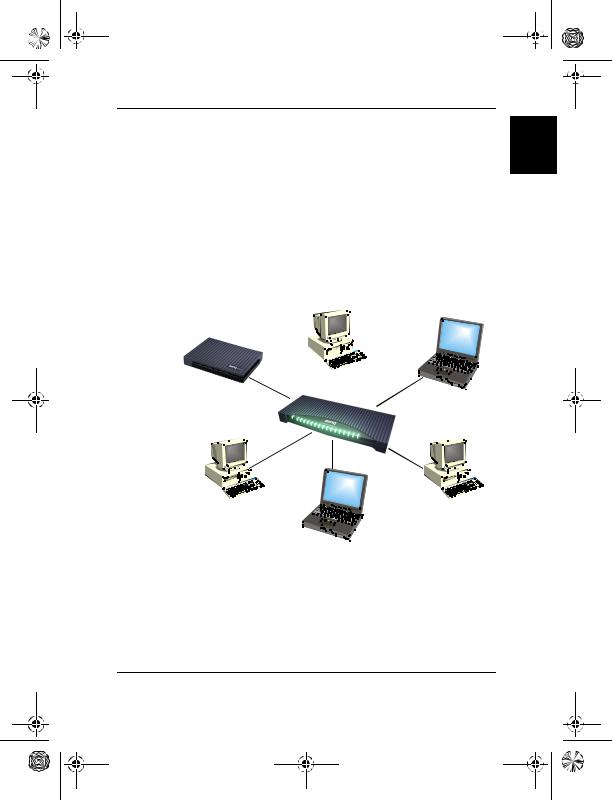
This SP0005/SP0008/SP0016 high performance Fast Ethernet switch provides five/eight/sixteen Fast Ethernet ports to segment network traffic, extend Fast Ethernet connection distance, and convert data packets between different transmission speeds. This Fast Ethernet Switch provides shielded RJ-45 ports both with 10Base-T and 100Base-TX Autonegotiation capability and MDI/MDI-X auto crossover. All ports in this switch support Full-Duplex and Half-Duplex operation modes. The Fast Ethernet Switch is typically used to segment network traffic that can improve the network performance by increasing the total bandwidth as illustrated in Figure 1-1.
Windows 98/95/2000
ADSL/Cable modem |
|
Windows Me/XP/NT |
|
English
Linux OS |
Server |
|
Mac OS |
Figure 1-1
This Fast Ethernet Switch utilizes stored-and-forward switching architecture that filters and forwards data after the complete data packet is received and examined to be free of errors. With one set of status LEDs for each individual port, the switch operation status can be easily monitored. Their slim and compact design allows direct placing on the desktop or conveniently mounted on the wall or the side of a desk to accommodate cabling consideration.
1. Introduction - 1

8PUG.book Page 2 Friday, August 9, 2002 5:32 PM
English
1.2. Features & Specifications
1.2.1. Features
•Compliant with IEEE 802.3 10Base-T Ethernet and 802.3u 100Base-TX Fast Ethernet Standards.
•Provides 5/8/16 ports for 10Base-T/100Base-TX, standard RJ-45 connectors.
•All RJ-45 ports supports 10Base-T/100Base-TX and Full-Duplex/Half- Duplex Auto-negotiation function.
•Supports MDI/MDI-X auto crossover.
•Supports store-and-forward switching mechanism.
•Plug-and-Play.
•Performs non-blocking full wire speed rate.
•Supports up to 4K/2K/8K (5/8/16 ports) MAC addresses table / hashing algorithm on address learning.
•Supports Aging function and 802.3x flow control for full Duplex and collision-based backpressure function for half duplex operation.
•128K/128K/512K (5/8/16 ports) Bytes buffer memory.
•Automatic address learning, address aging and address migration.
•Simple and economical way to bridge 10Base-T network and 100BaseTX network.
•Front panel status LEDs.
•Desktop size.
•Wall mountable.
1.2.2. Technical Specifications
Ethernet Standards |
IEEE 802.3 10Base-T, 802.3u 100Base-TX |
|||
|
|
|
|
|
|
Power |
Steady |
Power On |
|
|
|
|
||
|
Off |
Power Off |
||
|
|
|||
|
|
|
|
|
LED report |
100 M |
Steady (LNK) |
A valid network connection established |
|
(Green) |
Flashing (ACT) |
Transmitting or receiving data |
||
|
||||
|
|
|
|
|
|
10 M |
Steady (LNK) |
A valid network connection established |
|
|
(Yellow) |
Flashing (ACT) |
Transmitting or receiving data |
|
|
|
|
|
|
Cable |
10Base-T: 2-pair UTP Cat. 3,4,5, up to 100m (328 ft) |
|||
100Base-TX: 2-pair UTP Cat. 5, up to 100m (328 ft) |
||||
|
||||
|
|
|
||
Switching Method |
Store-and-forward |
|
||
|
|
|||
Forwarding Rate |
14,880pps for 10Mbps; 148,800pps for 100Mbps |
|||
|
|
|
|
|
1. Introduction - 2

8PUG.book Page 3 Friday, August 9, 2002 5:32 PM
1.2.3. Physical Specifications
|
|
English |
|
AC Input |
50-60Hz, External power adapter |
||
|
|||
|
|
|
|
Operating Temperature |
0°C ~ 50°C (32°F ~ 122°F ) |
|
|
|
|
|
|
Storage Temperature |
-20°C ~ 70°C (-4°F ~ 158°F ) |
|
|
|
|
|
|
Humidity |
10% ~ 90% non-condensing |
|
|
|
|
|
|
|
FCC part 15 Class B, CE Mark, VCCI Class B, C-TICK |
|
|
Emission Compliance |
for SP0005 & SP0008 |
|
|
FCC Class A, CE Mark, VCCI Class A, C-TICK |
|
||
|
|
||
|
for SP0016 |
|
|
|
|
|
|
Safety |
UL/CSA |
|
|
|
|
|
|
|
162mm x 103mm x 32mm (SP0005) |
|
|
Dimension |
162mm x 103mm x 32mm (SP0008) |
|
|
|
301mm x 125mm x 32mm (SP0016) |
|
|
|
|
|
|
Net Weight |
250g (SP0005); 250g (SP0008); 540g (SP0016) |
|
|
|
|
|
1.3. Terminology
PWR:
This Green LED lights when the power adapter is mounted.
LINK/ACT 10/100:
The Yellow LED lights when there is a valid 10-Base data linked on the port. And Green LED lights for 100-Base data linked. LED lights blinking when either 10-Base or 100-Base data is transmitted.
1.4. Package contents
The package should contain the following items:
SP0005/SP0008/SP0016 x 1
AC power adapter x 1
This User’s Guide
IF any item is found missing or damaged, please contact your local BenQ reseller for replacement.
1. Introduction - 3
8PUG.book Page 4 Friday, August 9, 2002 5:32 PM
English
2.Installation
2.1. Operating Environment
This switch must be installed and operated within the limits of specified operating temperature and humidity (see previous section under Specifications).
•Do not place objects on top of the unit.
•Do not obstruct any vents at the sides of the unit.
•Do not position the unit near any heating source such as heater, radiator, or direct exposure to sun.
•Prevent entering of water and moisture into the unit.
•If necessary, use dehumidifier to reduce humidity.
•Always avoid dust and dirt.
•Allow some space between the product and the surroundings to facilitate dissipation of heat generated inside the switch.
2.2.Connecting to network devices
The RJ-45 ports on the switch are designed as MDI/MDI-X auto crossover ports which allow using straight-through cables to connect any port on this switch to network device.
Connect one end of the network cable to the RJ-45 port on the rear panel, and then connect the other end of the network cable to the RJ-45 port on the network device. Follow the same procedure to connect all the RJ-45 ports of the switch. The UTP network cables must comply with EIA/TIA 568 specifications and Category 5 standard for 100Mbps data transmission and Category 3, 4, 5 for 10Mbps connection. Maximum length, using UTP cable, between the switch and connected device is 100 meters (328ft). Once the network cable is connected to both ends and the attached network device is powered on, the green LINK/ACT 10/100 LED should be lit (for 100-Base data linked by auto-negotiation).
2.3. Connecting the power
Connect the output end of the power adapter to the power connector on the rear panel of the unit. Connect the power adapter to the power outlet. The green Power LED on the front panel should be lit.
2. Installation - 4
8PUG.book Page 5 Friday, August 9, 2002 5:32 PM
3. Trouble Shooting
The SP0005/SP0008/SP0016 can be easily monitored by its LED indicators. Please follow the troubleshooting steps below to solve any problem you may encounter during installation or implementation of the SP0005/ SP0008/SP0016.
1. Power LED is not lit
Check if the power cord is properly connected to the external power adapter and the power outlet. Make sure the DC power jack is firmly plugged into the power socket of the switch.
2.100M Link/Activity(Green) is not lit when connect to
100 Mbps device
•Check the power switch of the network device attached to the switch; make sure it is turned ON.
•Check the network cable; make sure it is properly connected to the switch and the network device.
•Check the network cable; make sure the UTP cables comply with EIA/ TIA 568 and Category 5 specification.
Please perform the following tests
•Please check whether the RJ-45 cable is functional. Replace with another working cable and see whether the condition can be improved.
•Use another port on the SP0005/SP0008/SP0016. If a link can be established this way, the first port is faulty. Please contact your local BenQ dealer for assistant.
•Make sure that all devices are connected to the network.
•Please ensure that the network adapter cards installed in the workstation or other devices to the switch are in well working condition.
[!] Contact your dealer if problem persists.
3. Trouble Shooting - 5
English

8PUG.book Page i Wednesday, July 31, 2002 10:31 PM
|
Inhalt |
|
1. |
Einführung ............................................................................. |
1 |
|
1.1. Produktübersicht ........................................................................... |
1 |
|
1.2. Features & technische Daten ...................................................... |
2 |
|
1.2.1. Features .............................................................................................. |
2 |
|
1.2.2. Technische Daten ............................................................................. |
2 |
|
1.2.3. Technische Daten ............................................................................. |
3 |
|
1.3. Beschreibung ................................................................................... |
3 |
|
1.4. Packungsinhalt ................................................................................. |
3 |
2. |
Installation ............................................................................. |
4 |
|
2.1. Betriebsumgebung ......................................................................... |
4 |
|
2.2. Anschluss an Netzwerkgeräte .................................................... |
4 |
|
2.3. Stromanschluss ............................................................................... |
4 |
3. |
Problembehebung ............................................................... |
5 |
i

8PUG.book Page 1 Wednesday, July 31, 2002 10:31 PM
1.Einführung
1.1. Produktübersicht
Dieser SP0005/SP0008/SP0016 High Performance Fast Ethernet Switch bietet 5/8/16 Fast Ethernet-Schnittstellen für das Segmentieren von Netzwerkverkehr, für das Erweitern der Fast EthernetVerbindungsentfernung und für das Umwandeln von Datenpaketen in unterschiedlichen Übertragungsgeschwindigkeiten. Dieser Fast Ethernet Switch bietet abgeschirmte RJ-45-Schnittstellen mit sowohl 10Base-T als auch 100Base-TX Auto-Negotiation-Kapazitäten und MDI/MDI-X-Auto- Crossover. Alle Schnittstellen des Switches unterstützen die Betriebsmodi Full-Duplex und Half-Duplex. Der Fast Ethernet Switch wird normalerweise benutzt, um Netzwerkverkehr zu segmentieren und so die Netzwerkleistung zu verbessern, indem die gesamte Bandbreite erhöht wird. Siehe Abb. 1-1.
Windows 98/95/2000
ADSL-/Kabelmodem |
Windows Me/XP/NT |
|
Deutsch
Betriebssystem Linux |
Server |
|
|
|
Betriebssystem Mac |
Abb. 1-1
Der Fast Ethernet Switch benutzt einen "Stored-and-Forward"- Umschaltmechanismus, der Daten filtert und weiter sendet, nachdem das komplette Datenpaket empfangen und auf Fehler überprüft wurde. Jede individuelle Schnittstelle besitzt einen eigenen Satz von Status-LEDs, so dass der Status der Umschaltoperation leicht erkannt werden kann. Das schmale und kompakte Gerät lässt sich direkt auf dem Schreibtisch benutzen oder, abhängig von den Kabelanschlüssen, an einer Wand oder der Seite eines Tisches anbringen.
1. Einführung - 1
8PUG.book Page 2 Wednesday, July 31, 2002 10:31 PM
Deutsch
1.2. Features & technische Daten
1.2.1. Features
•Kompatibel mit IEEE 802.3 10Base-T Ethernet und 802.3u 100Base-TX Fast Ethernet Standards.
•Bietet 5/8/16 Schnittstellen für 10Base-T/100Base-TX, Standard RJ-45 Anschlüsse.
•Alle RJ-45-Schnittstellen unterstützen 10Base-T/100Base-TX und Full- Duplex/Half-Duplex Auto-Negotiation-Funktion.
•Unterstützt MDI/MDI-X Auto-Crossover.
•nterstützt "Store-and-Forward"-Umschaltmechanismus.
•Plug-and-Play
•Ermöglicht nicht blockierte volle Kabelgeschwindigkeiten.
•Unterstützt bis zu 4K/2K/8K (5/8/16 Schnittsellen) MACAdressentabelle / Hashing-Algorithmus bei Adressen-Lernen.
•Unterstützt Aging-Funktion und 802.3x Flusskontrolle für Full-Duplex und Kollision-basierte Backpressure-Funktion für Half-Duplex- Operation.
•128K/128K/512K (5/8/16 Schnittstellen) Bytes-Puffer-Speicher.
•Automatisches Adressen-Lernen, Adressen-Aging und AdressenMigration.
•Einfache und und sparsame Weise zum Überbrücken von 10Base-T- Netzwerk und 100Base-TX-Netzwerk.
•Status-LEDs auf Vorderseite
•Schreibtischgröße.
•An Wand montierbar.
1.2.2. Technische Daten
Ethernet-Standards |
IEEE 802.3 10Base-T, 802.3u 100Base-TX |
|||
|
|
|
|
|
|
Strom |
Ständig |
Strom ein |
|
|
|
|
||
|
Aus |
Strom aus |
||
|
|
|||
|
|
|
|
|
|
100 M |
Ständig (LNK) |
Eine gültige Netzwerkverbindung wurde |
|
|
erstellt |
|||
LED-Anzeige |
(Grün) |
|
||
|
|
|||
Aufblinkend (ACT) |
Daten werden übertragen oder empfangen |
|||
|
|
|||
|
|
|
|
|
|
10 M |
Ständig (LNK) |
Eine gültige Netzwerkverbindung wurde |
|
|
erstellt |
|||
|
(Gelb) |
|
||
|
|
|
||
|
Aufblinkend (ACT) |
Daten werden übertragen oder empfangen |
||
|
|
|||
|
|
|
|
|
Kabel |
10Base-T: 2-pair UTP Cat. 3,4,5, bis zu 100m (328 ft) |
|||
100Base-TX: 2-pair UTP Cat. 5, bis zu 100m (328 ft) |
||||
|
||||
|
|
|
||
Umschaltmethode |
Store-and-Forward |
|
||
|
|
|||
Forwarding-Rate |
14,880pps für 10Mbps; 148,800pps für 100Mbps |
|||
|
|
|
|
|
1. Einführung - 2
8PUG.book Page 3 Wednesday, July 31, 2002 10:31 PM
1.2.3. Technische Daten
Wechselstromeingabe |
50-60Hz, Externes Netzteil |
|
|
|
|
|
|
|
|
Betriebstemperatur |
0°C ~ 50°C (32°F ~ 122°F ) |
|
|
|
|
|
|
|
|
Lagertemperatur |
-20°C ~ 70°C (-4°F ~ 158°F ) |
|
|
|
|
|
|
|
|
Luftfeuchtigkeit |
10% ~ 90% nicht kondensierend |
|
|
|
Deutsch |
||||
|
|
|
||
|
FCC Teil 15 Klasse B, CE Mark, VCCI Klasse B, C-TICK |
|
||
Emissionsrichtlinien |
für SP0005 & SP0008 |
|
||
|
|
|||
FCC Klasse A, CE Mark, VCCI Klasse A, C-TICK |
|
|
||
|
|
|
||
|
für SP0016 |
|
|
|
|
|
|
|
|
Sicherheit |
UL/CSA |
|
|
|
|
|
|
|
|
|
162mm x 103mm x 32mm (SP0005) |
|
|
|
Abmessungen |
162mm x 103mm x 32mm (SP0008) |
|
|
|
|
301mm x 125mm x 32mm (SP00016) |
|
|
|
|
|
|
|
|
Nettogewicht |
250g (SP0005); 250g (SP0008); 540g (SP0016) |
|
|
|
|
|
|
|
1.3. Beschreibung
PWR:
Diese grüne LED leuchtet auf, wenn das Netzteil angeschlossen ist.
LINK/ACT 10/100:
Diese gelbe LED leuchtet auf, wenn gültige 10-Base-Daten an die Schnittstelle angeschlossen sind. Die grüne LED leuchtet für angeschlossene 100-Base-Daten auf. LED blinkt, wenn entweder 10-Base- oder 100-Base-Daten übertragen werden.
1.4. Packungsinhalt
Die Packung sollte die folgenden Einzelteile enthalten: SP0005/SP0008/SP0016 x 1
1 Netzteil
Dieses Benutzerhandbuch
Wenn ein Teil fehlen oder beschädigt sein sollte, kontaktieren Sie bitte
Ihren örtlichen BenQ-Händler, um Ersatz zu erhalten.
1. Einführung - 3

8PUG.book Page 4 Wednesday, July 31, 2002 10:31 PM
Deutsch
2.Installation
2.1. Betriebsumgebung
Der Switch muss in einer Umgebung installiert und betrieben werden, in der die Grenzwerte für Betriebstemperatur und Feuchtigkeit eingehalten werden (siehe Technische Daten).
•Stellen Sie keine Gegenstände auf die Einheit.
•Verdecken Sie nicht die Lüftungsschlitze auf den Seiten der Einheit.
•Stellen Sie die Einheit nicht in die Nähe einer Hitzequelle, z. B. einen Heizkörper, oder in direktes Sonnenlicht.
•Vermeiden Sie, dass Wasser oder Feuchtigkeit in die Einheit eindringt
•Benutzen Sie, falls nötig, einen Entfeuchter, um die Luftfeuchtigkeit zu reduzieren.
•Vermeiden Sie Staub und Schmutz.
•Sorgen Sie für Abstand zwischen dem Gerät und seiner Umgebung, um die Wärmeableitung vom Inneren des Switches zu erleichtern.
2.2.Anschluss an Netzwerkgeräte
Die RJ-45-Schnittstellen des Switches wurden als MDI/MDI-X-Auto- Crossover-Schnittstellen entworfen, die das Benutzen von Straight- Through-Kabeln ermöglichen, um eine beliebige Schnittstelle des Switches mit einem Netzwerkgerät zu verbinden.
Schließen Sie das eine Ende des Netzwerkkabels an die RJ-45-Schnittstelle auf der Rückseite an. Schließen Sie dann das andere Ende des Netzwerkkabels and die RJ-45-Schnittstelle des Netzwerkgeräts an. Gehen Sie auf die gleiche Weise vor, um alle RJ-45-Schnittstellen des Switches anzuschließen. Die UTP-Netzwerkkabel müssen mit den EIA/ TIA 568-Werten und dem Kategorie-5-Standard für 100MbpsDatenübertragung sowie Kategorie 3, 4, 5 für 10Mbps-Verbindung übereinstimmen. Die maximale Länge beim Benutzen eines UTP-Kabels zwischen dem Switch und angeschlossenem Gerät ist 100 Meter (328ft). Sobald das Netzwerkkabel an beiden Enden angeschlossen und das angeschlossene Netzwerkgerät eingeschaltet ist, sollte die grüne LINK/ ACT 10/100 LED (für mit Auto-Negotiation verbundene100-Base-Daten) aufleuchten.
2.3. Stromanschluss
Schließen Sie das Ausgabeende des Netzteils an den Stromanschluss auf der Rückseite der Einheit an. Schließen Sie das Netzteil an eine Netzquelle an. Die grüne Strom-LED auf der Vorderseite sollte aufleuchten.
2. Installation - 4
8PUG.book Page 5 Wednesday, July 31, 2002 10:31 PM
3. Problembehebung
SP0005/SP0008/SP0016 kann mit Hilfe der LED-Anzeigen einfach überwacht werden. Gehen Sie bitte wie unten angegeben vor, um Probleme zu beheben, auf die Sie während der Installation oder des Benutzens von SP0005/SP0008/SP0016 stoßen.
1. Strom-LED leuchtet nicht auf
Überprüfen Sie, ob das Netzkabel korrekt an das externe Netzteil und die Netzquelle angeschlossen ist. Gehen Sie sicher, dass der Gleichstromstecker fest in die Buchse des Switches eingesteckt ist.
2.100M Link/Aktivität (Grün) leuchtet bei Verbindung zu
100 Mbps-Gerät nicht auf
•Überprüfen Sie, ob der Stromschalter des an den Switch angeschlossen Netzwerkgeräts eingeschaltet ist.
•Überprüfen Sie das Netzwerkkabel; gehen Sie sicher, dass es ordnungsgemäß an den Switch und das Netzwerkgerät angeschlossen ist.
•Überprüfen Sie das Netzwerkkabel; gehen Sie sicher, dass die UTPKabel mit den Werten für EIA/TIA 568 und Kategorie 5 übereinstimmen.
Führen Sie bitte die folgenden Tests durch
•Überprüfen Sie, ob das RJ-45-Kabel funktionsfähig ist. Ersetzen Sie es durch ein anderes funktionierendes Kabel und sehen, ob sich der Zustand verbessert.
•Benutzen Sie eine andere Schnittstelle von SP0005/SP0008/SP0016. Wenn eine Verbindung auf diese Weise hergestellt werden kann, ist die erste Schnittstelle fehlerhaft. Kontaktieren Sie bitte Ihren örtlichen BenQ-Händler für Hilfe.
•Gehen Sie sicher, das alle Geräte an das Netzwerk angeschlossen sind.
•Gehen Sie sicher, dass die Netzwerk-Adapterkarten, die in die Workstation installiert sind, oder andere Geräte, die an den Switch angeschlossen sind, einwandfrei funktionieren.
[!]Kontaktieren Sie Ihren Händler, wenn das Problem weiterhin besteht.
3.Problembehebung - 5
Deutsch

8PUG.book Page i Wednesday, July 31, 2002 10:29 PM
|
Sommarie |
|
1. |
Introduction ......................................................................... |
1 |
|
1.1. Présentation .................................................................................... |
1 |
|
1.2. Fonctionnalités & Caractéristiques ............................................ |
2 |
|
1.2.1. Fonctionnalités .................................................................................. |
2 |
|
1.2.2. Caractéristiques techniques ........................................................... |
2 |
|
1.2.3. Caractéristiques physiques ............................................................. |
3 |
|
1.3. Terminologie ................................................................................... |
3 |
|
1.4. Contenu de l’emballage ................................................................ |
3 |
2. |
Installation ............................................................................. |
4 |
|
2.1. Environnement d’exploitation ..................................................... |
4 |
|
2.2. Connexion aux périphériques de réseau ................................. |
4 |
|
2.3. Connexion de l’alimentation ....................................................... |
4 |
3. |
Dépannage ............................................................................ |
5 |
i
 Loading...