


FCC_E.fm Page 1 Friday, August 9, 2002 5:28 PM
FCC Warning
The equipment has been tested and found to comply with the limits for a Class A digital device, pursuant to Part 15 of the FCC rules. These limits are designed to provide reasonable protection against harmful interference when the equipment is operated in a commercial environment. This equipment generate, uses, and can radiate radio frequency energy and, if not installed and used in accordance with this user's guide, may cause harmful interference to radio communications. Operation of this equipment in a residential area is likely to cause harmful interference in which case the user will be required to correct the interference at his own expense.
CE Mark Warning
This is a Class A product. In a domestic environment, this product may cause radio interference, in which case the user may be required to take adequate measures.
Trademarks
Copyright ©2002 BenQ Corporation.
Contents subject to change without prior notice. BenQ is a registered trademark of BenQ Corporation. All other trademarks belong to their respective proprietors.
Copyright Statement
No part of this publication may be reproduced in any form or by any means or used to make any derivative such as translation, transformation, or adaptation without permission from BenQ Corporation.

FCC_E.fm Page 2 Friday, August 9, 2002 5:28 PM
SE&SS0116.book Page i Friday, August 9, 2002 5:28 PM
Table of Contents |
|
1. Introduction ............................................................................................ |
1 |
1.1. Product Overview ................................................................................................ |
1 |
1.2. Features & Specifications ..................................................................................... |
1 |
1.2.1. Features ....................................................................................................................... |
1 |
1.2.2. Technical Specifications ............................................................................................ |
1 |
1.2.3. Physical Specifications .............................................................................................. |
2 |
1.3. Product outlook and LED Display .................................................................... |
2 |
1.3.1. Product outlook ........................................................................................................ |
2 |
1.3.2. LED Display ................................................................................................................ |
3 |
1.4. Package contents ................................................................................................... |
3 |
2. Installation ................................................................................................ |
3 |
2.1. Operating Environment ....................................................................................... |
3 |
2.2. Connecting to network devices ........................................................................ |
3 |
2.3. Connecting the power ......................................................................................... |
4 |
3. Trouble Shooting .................................................................................. |
4 |
Appendix: ..................................................................................................... |
4 |
Ordering Information .................................................................................................. |
4 |
i

SE&SS0116.book Page ii Friday, August 9, 2002 5:28 PM
ii
SE&SS0116.book Page 1 Friday, August 9, 2002 5:28 PM
1.Introduction
1.1. Product Overview
This user’s manual describes and illustrates the installation method and usage of the 16/24 port Fast Ethernet Switch. The rack-mount switch (SE0016/SE0024) introduced here provides 16/24 10/100Mbps Fast Ethernet ports to segment traffic, extend Fast Ethernet connection distance, and convert data packets between different transmission speeds. This Fast Ethernet Switch provides shielded RJ-45 ports both with 10Base-T and 100Base-TX Auto-negotiation capability and MDI/MDIX auto crossover. All ports in this switch support Full-Duplex and Half-Duplex operation modes.
Furthermore, this powerful Fast Ethernet Switch utilizes stored-and-forward switching architecture that filters and forwards data after the complete data packet is received and examined to be free of errors. With one set of status LEDs for each individual port, the switch operation status can be easily monitored. The switch is rack-mount design that can be mounted on the industrial standard 19 inches rack in the enterprise wiring center.
1.2. Features & Specifications
1.2.1. Features
•16/24 port 10/100Base-TX, RJ-45 connector.
•Innovative Display panel design.
•Auto-negotiation for speed and half/full duplex.
•Complies with IEEE802.3 and IEEE802.3u Standards.
•Auto-MDI/MDIX detection.
•Support "True non-blocking architecture."
•Full wire speed forwarding.
•Operating at maximum packet filtering and forwarding rate.
•Support for Store-and-forward of packet switching.
•Flow Control.
•Broadcast storm control.
•Standard 19" Rack-mount size.
1.2.2. Technical Specifications
• Ethernet Standards |
|
|
IEEE 802.3 10Base-T, 802.3u 100Base-TX. |
|
• Protocol |
|
|
CSMA/CD |
|
• 10/100Mbps Ports |
|
|
RJ-45 x 16 (SE0016), RJ-45 x 24 (SE0024) |
|
• MAC address |
|
|
8k (SE0016), 4K (SE0024) |
|
• Buffer Memory |
|
|
512K Bytes (SE0016), 768K Bytes (SE0024) |
|
• LED report |
|
|
per unit: Power Status. |
|
|
|
|
per port: 10/100M; |
|
|
|
|
LNK/ACT (port number); |
|
|
|
|
FDX/COL. |
|
• Transmission Method |
|
|
Store-and-forward |
|
• Forwarding Rate |
|
|
14,880pps for 10Mbps; |
|
|
|
|
148,800pps for 100Mbps |
|
|
|
|
|
|
|
1. Introduction - 1 |
|||
|
|
|
|
|
|
|
|
|
|
|
|
|
|
|
English

SE&SS0116.book Page 2 Friday, August 9, 2002 5:28 PM
English
1.2.3. Physical Specifications
• Power |
90VAC~240VAC 50Hz~60Hz |
• Operating Temperature |
0°C ~ 50°C |
• Storage Temperature |
-20°C ~ 70°C |
• Operating Humidity |
10% ~ 90% RH |
• Storage Humidity |
5% ~ 90% RH |
• Emission Compliance |
FCC part 15 Class A, CE Mark, VCCI, |
|
C-Tick |
• Safety |
UL/CSA |
• Dimension |
W 435 mm x D 221 mm x H 44mm |
|
(17.1”x 8.7”x1.8”). Standard 19” rack-mountable |
|
size, one-unit-height. |
• Net Weight |
2.9kg (6.41b) |
1.3. Product outlook and LED Display
1.3.1. Product outlook
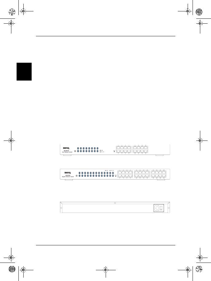
Front View
SE0016 Front Panel:
SE0024 Front Panel:
Rear View
SE0016/SE0024 Rear Panel:
1. Introduction - 2
SE&SS0116.book Page 3 Friday, August 9, 2002 5:28 PM
1.3.2. LED Display
|
|
|
English |
|
Steady |
Power on |
|
LEDs |
Status |
Indication |
|
Power |
|
|
|
Off |
Power off |
|
|
|
|
||
100M |
On |
100M mode |
|
(Green) |
Off |
10M mode |
|
|
Steady |
A valid network connection established. |
|
|
LNK stands for LINK. |
|
|
Port Number |
|
|
|
Flashing |
Activity, Transmitting, or receiving data. |
|
|
(Green) |
|
||
Off |
Neither valid network connection nor transmitting |
|
|
|
|
||
|
established. |
|
|
|
|
|
|
|
Steady |
Connection in full duplex mode. |
|
FDX/COL |
FDX stands for FULL-DUPLEX. |
|
|
|
|
||
(Yellow) |
Flashing |
Collision occurred. |
|
|
Off |
Connection in half-duplex mode. |
|
1.4. Package contents
Packing List
SE0016/SE0024 x 1
AC power cord x 1
This User’s Guide
Rack-mount ears with screws
Warranty Card
If any item is found missing or damaged, please contact your local BenQ reseller for replacement.
2.Installation
2.1. Operating Environment
This switch must be installed and operated within the limits of specified operating temperature and humidity (see previous section under Specifications).
•Do not place objects on top of the unit.
•Do not obstruct any vents at the sides of the unit.
•Do not position the unit near any heating source such as heater, radiator, or direct exposure to sun.
•Prevent entering of water and moisture into the unit.
•If necessary, use dehumidifier to reduce humidity.
•Always avoid dust and dirt.
•Allow some space between the product and the surroundings to facilitate dissipation of heat generated inside the switch.
2.2.Connecting to network devices
The RJ-45 ports on the switch are designed as MDI/MDIX auto crossover ports which allow using straight-through cables to connect any port on this switch to network device.
Connect one end of the network cable to the RJ-45 port on the front panel, and connect the other end of the network cable to the RJ-45 port on the network device. Follow the
2. Installation - 3
SE&SS0116.book Page 4 Friday, August 9, 2002 5:28 PM
English
same procedure to connect all the RJ-45 ports of the switch. The UTP network cables must comply with EIA/TIA 568 specifications and Category 5 standard for 100Mbps data transmission and Category 3, 4, 5 for 10Mbps connection. Maximum length, using UTP cable, between the switch and connected device is 100 meters (328ft). Once the network cable is connected to both ends and the attached network device is powered on, the LEDs should be lit.
2.3. Connecting the power
Connect the output end of the power cord to the power connector on the rear panel of the unit. Then connect the power cord to the power outlet. The green Power LED on the front panel should be lit.
3. Trouble Shooting
The SE0016/SE0024 can be easily monitored by its LED indicators. Please follow the troubleshooting steps below to solve any problem you may encounter during installation or implementation of the SE0016/SE0024.
1. Power LED is not lit
Check if the power cord is properly connected to the power outlet and is firmly plugged into the power socket of the switch.
2. Port Number(Green) is not lit when connected to a valid LAN device
•Check the power switch of the network device attached to the switch; make sure it is turned ON.
•Check the network cable; make sure it is properly connected to the switch and the network device.
•Check the network cable; make sure the UTP cables comply with EIA/TIA 568 and Category 5 specification.
Please perform the following tests:
•Please check whether the RJ-45 cable is functional. Replace with another working cable and see whether the condition can be improved.
•Use another port on the SE0016/SE0024. If a link can be established this way, the first port is faulty. Please contact your local BenQ dealer for assistant.
•Make sure that all devices are connected to the network.
•Please ensure that the network adapter cards installed in the workstation or other devices to the switch are in well working condition.
[!] Contact your dealer if problem persists.
Appendix:
Ordering Information
Part Number |
Model |
Description |
|
|
|
99.332N2.101 |
SE0016 |
16-Port Fast Ethernet Switch |
|
|
|
99.334N2.101 |
SE0024 |
24-Port Fast Ethernet Switch |
|
|
|
3. Trouble Shooting - 4

SE&SS0116.book Page i Friday, August 9, 2002 5:47 PM
Inhalt |
|
1. Einführung ................................................................................................ |
1 |
1.1. Produktübersicht .................................................................................................. |
1 |
1.2. Features & technische Daten ............................................................................. |
1 |
1.2.1. Features ....................................................................................................................... |
1 |
1.2.2. Technische Daten ...................................................................................................... |
1 |
1.2.3. Physische Daten ......................................................................................................... |
2 |
1.3. Produktübersicht und LED-Anzeige ................................................................. |
2 |
1.3.1. Produktübersicht ....................................................................................................... |
2 |
1.3.2. LED-Anzeige ............................................................................................................... |
3 |
1.4. Packungsinhalt ........................................................................................................ |
3 |
2. Installation ................................................................................................ |
3 |
2.1. Betriebsumgebung ................................................................................................ |
3 |
2.2. Anschluss an Netzwerkgeräte ........................................................................... |
3 |
2.3. Stromanschluss ...................................................................................................... |
4 |
3. Problembehebung ................................................................................. |
4 |
Anhang: ......................................................................................................... |
4 |
Bestellinformation ......................................................................................................... |
4 |
i

SE&SS0116.book Page ii Friday, August 9, 2002 5:47 PM
ii
SE&SS0116.book Page 1 Friday, August 9, 2002 5:47 PM
1.Einführung
1.1. Produktübersicht
Dieses Benutzerhandbuch beschreibt und zeigt die Installation und das Benutzen des 16/24Schnittstellen Fast Ethernet Switches. Der hier vorgestellte in einem Einbaugehäuse installierte Switch (SE0016/SE0024) bietet 16/24 10/100Mbps Fast Ethernet-Schnittstellen zum Segmentieren von Verkehr, zum Erweitern von Fast Ethernet-Verbindungsentfernungen und zum Umwandeln von Datenpaketen in unterschiedlichen Übertragungsgeschwindigkeiten. Dieser Fast Ethernet Switch bietet abgeschirmte RJ-45-Schnittstellen mit sowohl 10Base-T als auch 100Base-TX Auto-Negotiation-Kapazitäten und MDI/MDIX-Auto-Crossover. Alle Schnittstellen des Switches unterstützen die Betriebsmodi Full-Duplex und Half-Duplex.
Darüber hinaus benutzt dieser leistungsfähige Fast Ethernet Switch einen "Stored-and-For- ward"-Umschaltmechanismus, der Daten filtert und weiter sendet, nachdem das komplette Datenpaket empfangen und auf Fehler überprüft wurde. Jede individuelle Schnittstelle besitzt einen eigenen Satz von Status-LEDs, so dass der Status der Umschaltoperation leicht erkannt werden kann. Der Switch ist für die Montage in einem standarmäßigen 19Zoll Einbaugehäuse für Verdrahtung in Firmen konzipiert worden.
1.2. Features & technische Daten
1.2.1. Features
•16/24-Schnittstellen 10/100Base-TX, RJ-45-Anschluss.
•Innovatives Anzeigedesign.
•Auto-Negotiation für Geschwindigkeit und Half-/Full-Duplex.
•Entspricht den Standards IEEE802.3 und IEEE802.3u.
•Auto-MDI/MDIX-Erkennung.
•Unterstützung von "True-Non-Blocking"-Mechanismus.
•Forwarding mit voller Drahtgeschwindigkeit.
•Betrieb bei maximaler Paketfilterund Forwarding-Rate.
•Unterstützt "Store-and-Forward"-Paketumschaltung.
•Flusskontrolle.
•Broadcast-Storm-Kontrolle.
•Standardmäßige 19"-Einbaugehäusegröße.
1.2.2. Technische Daten
• Ethernet-Standards |
|
|
IEEE 802.3 10Base-T, 802.3u 100Base-TX. |
|
• Protokoll |
|
|
CSMA/CD |
|
• 10/100Mbps-Schnittstellen |
|
|
RJ-45 x 16 (SE0016), RJ-45 x 24 (SE0024) |
|
• MAC-Adresse |
|
|
8k (SE0016), 4K (SE0024) |
|
• Puffer-Speicher |
|
|
512K Bytes (SE0016), 768K Bytes (SE0024) |
|
• LED-Report |
|
|
pro Einheit: Strom-Status. |
|
|
|
|
pro Schnittstelle: 10/100M; |
|
|
|
|
|
LNK/ACT (Schnittstellennummer); |
|
|
|
|
FDX/COL. |
• Übertragungsmethode |
|
|
Store-and-Forward |
|
|
|
|
|
|
|
1. Einführung - 1 |
|||
|
|
|
|
|
|
|
|
|
|
|
|
|
|
|
Deutsch
SE&SS0116.book Page 2 Friday, August 9, 2002 5:47 PM
Deutsch
• Forwarding-Rate |
14,880pps für 10Mbps; |
|
148,800pps for 100Mbps |
1.2.3. Physische Daten
• Strom |
90VAC~240VAC 50Hz~60Hz |
• Betriebstemperatur |
0°C ~ 50°C |
• Lagertemperatur |
-20°C ~ 70°C |
• Luftfeuchtigkeit während Betrieb |
10% ~ 90% RH |
• Luftfeuchtigkeit während Lagerung |
5% ~ 90% RH |
• Emissionsrichtlinien |
FCC Teil 15 Klasse A, CE Mark, VCCI, |
|
C-Tick |
• Sicherheit |
UL/CSA |
• Abmessungen |
W 435mm x T 221mm x H 44mm |
|
(17.1”x 8.7”x1.8”). Standardmäßige |
|
19"-Einbaugehäusegröße, Eine-Einheit-Höhe. |
• Nettogewicht |
2.9kg (6.41b) |
1.3. Produktübersicht und LED-Anzeige
1.3.1. Produktübersicht
Vorderseite
Vorderseite von SE0016:
Vorderseite von SE0024:
Rückseite
Rückseite von SE0016/SE0024:
1. Einführung - 2
SE&SS0116.book Page 3 Friday, August 9, 2002 5:47 PM
1.3.2. LED-Anzeige
LEDs |
Status |
Anzeige |
|
|
|
Strom |
Ständig |
Strom ein |
|
|
|
Aus |
Strom aus |
|
|
||
|
|
|
|||
100M |
Ein |
100M-Modus |
|
|
|
(Grün) |
Aus |
10M-Modus |
|
|
|
Deutsch |
|||||
|
Ständig |
Eine gültige Netzwerkverbindung wurde erstellt. |
|
||
Schnittstellen |
LNK steht für LINK. |
|
|||
nummer |
Aufblinkend |
Aktivität, Daten werden übertragen oder empfangen |
|
|
|
(Grün) |
Aus |
Weder gültige Netzwerkverbindung noch Übertragung wurde |
|
|
|
|
|
erstellt. |
|
|
|
|
Ständig |
Verbindung in Full-Duplex-Modus. |
|
|
|
FDX/COL |
FDX steht für FULL-DUPLEX. |
|
|
||
|
|
|
|||
(Gelb) |
Aufblinkend |
Kollision aufgetreten. |
|
|
|
|
Aus |
Verbindung in Half-Duplex-Modus. |
|
|
1.4. Packungsinhalt
Packungsliste
SE0016/SE0024 x 1 1 Netzkabel
Dieses Benutzerhandbuch Einbauschienen mit Schrauben Garantiekarte
Wenn ein Teil fehlen oder beschädigt sein sollte, kontaktieren Sie bitte Ihren örtlichen BenQ-Händler, um Ersatz zu erhalten.
2.Installation
2.1. Betriebsumgebung
Der Switch muss in einer Umgebung installiert und betrieben werden, in der die Grenzwerte für Betriebstemperatur und Feuchtigkeit eingehalten werden (siehe Technische Daten).
•Stellen Sie keine Gegenstände auf die Einheit.
•Verdecken Sie nicht die Lüftungsschlitze auf den Seiten der Einheit.
•Stellen Sie die Einheit nicht in die Nähe einer Hitzequelle, z. B. einen Heizkörper, oder in direktes Sonnenlicht.
•Vermeiden Sie, dass Wasser oder Feuchtigkeit in die Einheit eindringt.
•Benutzen Sie, falls nötig, einen Entfeuchter, um die Luftfeuchtigkeit zu reduzieren.
•Vermeiden Sie Staub und Schmutz.
•Sorgen Sie für Abstand zwischen dem Gerät und seiner Umgebung, um die Wärmeableitung vom Inneren des Switches zu erleichtern.
2.2.Anschluss an Netzwerkgeräte
Die RJ-45-Schnittstellen des Switches wurden als MDI/MDIX-Auto-Crossover-Schnitts- tellen entworfen, die das Benutzen von Straight-Through-Kabeln ermöglichen, um eine beliebige Schnittstelle des Switches mit einem Netzwerkgerät zu verbinden.
Schließen Sie das eine Ende des Netzwerkkabels an die RJ-45-Schnittstelle auf der Vorderseite an. Schließen Sie das andere Ende des Netzwerkkabels an die RJ-45-Schnittstelle des Netzwerkgeräts an. Gehen Sie auf die gleiche Weise vor, um alle RJ-45-Schnittstellen des
2. Installation - 3
SE&SS0116.book Page 4 Friday, August 9, 2002 5:47 PM
Deutsch
Switches anzuschließen. Die UTP-Netzwerkkabel müssen mit den EIA/TIA 568-Werten und dem Kategorie-5-Standard für 100Mbps-Datenübertragung sowie Kategorie 3, 4, 5 für 10Mbps-Verbindung übereinstimmen. Die maximale Länge beim Benutzen eines UTPKabels zwischen dem Switch und angeschlossenem Gerät ist 100 Meter (328ft). Sobald das Netzwerkkabel an beide Enden angeschlossen und das angeschlossene Netzwerkerät eingeschaltet wurde, sollten die LEDs aufleuchten.
2.3. Stromanschluss
Schließen Sie das Ausgabeende des Netzkabels an den Stromanschluss auf der Rückseite der Einheit an. Schließen Sie dann das Netzkabel an eine Netzquelle an. Die grüne StromLED auf der Vorderseite sollte aufleuchten.
3. Problembehebung
SE0016/SE0024 kann mit Hilfe der LED-Anzeigen einfach überwacht werden. Gehen Sie bitte wie unten angegeben vor, um Probleme zu beheben, auf die Sie während der Installation oder des Benutzens von SE0016/SE0024 stoßen.
1. Strom-LED leuchtet nicht auf
Überprüfen Sie, ob das Netzkabel korrekt an die Netzquelle angeschlossen und fest in die Strombuchse des Switches eingesteckt ist.
2.Schnittstellennummer (Grün) leuchtet nicht auf, wenn gültiges LANGerät angeschlossen ist
•Überprüfen Sie, ob der Stromschalter des an den Switch angeschlossen Netzwerkgeräts eingeschaltet ist.
•Überprüfen Sie das Netzwerkkabel; gehen Sie sicher, dass es ordnungsgemäß an den Switch und das Netzwerkgerät angeschlossen ist.
•Überprüfen Sie das Netzwerkkabel; gehen Sie sicher, dass die UTP-Kabel mit den Werten für EIA/TIA 568 und Kategorie 5 übereinstimmen.
•Führen Sie bitte die folgenden Tests durch:
•Überprüfen Sie, ob das RJ-45-Kabel funktionsfähig ist. Ersetzen Sie es durch an anderes funktionierendes Kabel und sehen, ob sich der Zustand verbessert.
•Benutzen Sie eine andere Schnittstelle von SE0016/SE0024. Wenn eine Verbindung auf diese Weise hergestellt werden kann, ist die erste Schnittstelle fehlerhaft. Kontaktieren Sie bitte Ihren örtlichen BenQ-Händler für Hilfe.
•Gehen Sie sicher, das alle Geräte an das Netzwerk angeschlossen sind.
•Gehen Sie sicher, dass die Netzwerk-Adapterkarten, die in die Workstation installiert sind, oder andere Geräte, die an den Switch angeschlossen sind, einwandfrei funktion-
ieren.
[!] Kontaktieren Sie Ihren Händler, wenn das Problem weiterhin besteht.
Anhang:
Bestellinformation
Teilenummer |
Modell |
Beschreibung |
|
|
|
99.332N2.101 |
SE0016 |
16-Schnittstellen Fast Ethernet Switch |
|
|
|
99.334N2.101 |
SE0024 |
24-Schnittstellen Fast Ethernet Switch |
|
|
|
3. Problembehebung - 4

SE&SS0116.book Page i Friday, August 9, 2002 5:51 PM
Sommarie |
|
1. Introduction ............................................................................................ |
1 |
1.1. Présentation ........................................................................................................... |
1 |
1.2. Fonctionnalités & Caractéristiques ................................................................... |
1 |
1.2.1. Fontionnalités ............................................................................................................. |
1 |
1.2.2. Caractéristiques techniques .................................................................................... |
1 |
1.2.3. Caractéristiques physiques ...................................................................................... |
2 |
1.3. Présentation du produit et Affichage LED ...................................................... |
2 |
1.3.1. Vues du produit ......................................................................................................... |
2 |
1.3.2. Affichage LED ............................................................................................................. |
3 |
1.4. Contenu de l’emballage ....................................................................................... |
3 |
2. Installation ................................................................................................ |
3 |
2.1. Envrionnement d’exploitation ............................................................................ |
3 |
2.2. Connexion aux périphériques de réseau ........................................................ |
3 |
2.3. Connexion de l’alimentation .............................................................................. |
4 |
3. Dépannage .............................................................................................. |
4 |
Appendice: ................................................................................................... |
5 |
Renseignements pour la commande ......................................................................... |
5 |
i
 Loading...