


®


 SD-13-4811
Bendix® ATR-1™ AntiLock Traction Relay Valve
TRACTION CONTROL
CONTROLLER SOLENOID
MOUNTING HOLES (4)
MOUNTING
BRACKET
SERVICE |
UNDRILLED |
PORT |
“CON” PORT |
SUPPLY
PORT
BODY |
|
DELIVERY |
|
PORT (4) |
2 PIN SOLENOID |
SUPPLY |
CONNECTOR |
PORT |
|
COVER PLATE FOR |
|
REMOTE MOUNT |
|
REMOTE MOUNTATR-1™ RELAYVALVE
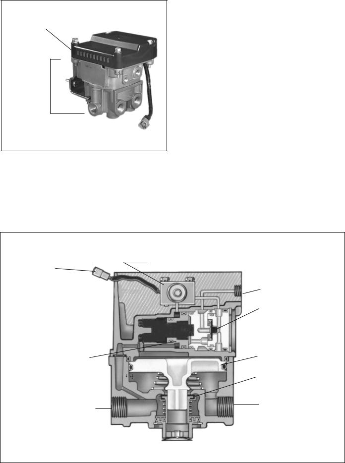
FIGURE 1 - ATR-1™ ANTILOCK TRACTION RELAY VALVE
DESCRIPTION
The ATR-1™ antilock traction relay is a specialized air brake valve developed for use on Bendix antilock/traction equipped vehicles.
It is essentially three separate valves working in combination in a single housing. An R-14™ style service relay is the base valve and is fitted with a modified cover containing a double check valve and a traction control solenoid. TheATR-1™ valve contains both air and electric components to provide the service braking and traction control (differential braking) functions. A Bendix antilock traction controller can be mounted to theATR-1™ valve or a cover plate can be installed and the antilock controller mounted elsewhere on the vehicle. When an ATR-1™ valve is combined with an antilock traction controller the resulting assembly is referred to as an antilock traction assembly.
The ATR-1™ valve replaces the standard relay valve used to control the rear axle service brakes and performs the standard relay function. Like the standard relay valve it replaces, the ATR-1™ valve (sometimes with attached antilock controller)
is normally mounted near the service brakes it serves. A mounting bracket, furnished with the valve, permits either frame or cross member mounting. All air connections on the ATR-1™ valve are identified for ease of installation. The letter identification and air line connections are shown below for reference.
EMBOSSED
ATR-1™ VALVE AIR CONNECTION |
IDENT. |
Supply (to reservoir) |
SUP |
Delivery (to brake Chamber) |
DEL |
|
|
Service (to brake valve rear delivery) |
SER |
Control (not drilled or threaded on ATR-1™ valve) |
CON |
The ATR-1™ valve is part of the R-12™ family of relay valves which includes the R-12™, R-14™, BP-R1™, AR-1™.
The internal components of the relay portion of all of these valves are interchangeable with the R-12™ valve and therefore the same basic components are used to service all of them. The ATR-1™ valve is available with various crack pressures to accommodate specific applications, however the standard is 4 psi.
1
CONTROLLER
ATR-1™ ANTILOCK
TRACTION RELAY
VALVE
FIGURE 2 - ANTILOCK TRACTION ASSEMBLY
OPERATION
GENERAL
Because theATR-1™ is essentially a relay valve, the following description of operation refers to its function in the vehicles air brake system and does not address all of the separate
antilock components and their operation. For a description of antilock operation, refer to the appropriate Service Data Sheet covering the electronic controller used with the ATR-1™ valve.
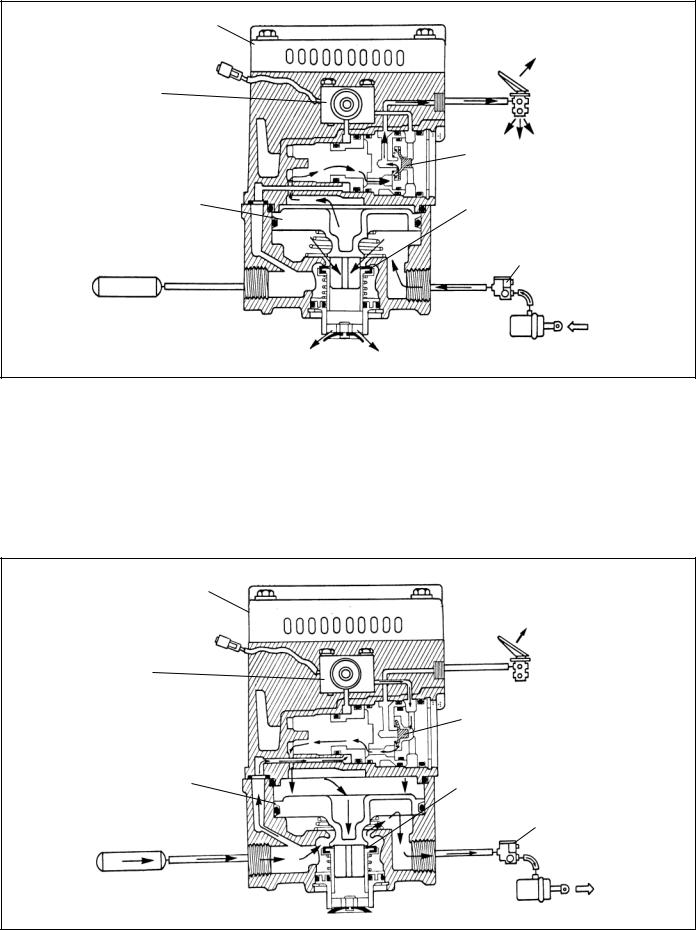
SERVICE BRAKES APPLYING (FIGURE 4)
Reservoir air pressure is present at the supply port and flows through internal body and cover passages to the supply of the normally closed (NC) traction control solenoid.
Brake application air enters the ATR-1™ valve’s service port and is conducted to the single check valve. The check valve diaphragm flexes in response to application pressure and seals the passage to the open exhaust of the traction solenoid. Air flows through the service piston then through the center of the blend back and through a passage in the cover to the top of the service relay piston. In response to air pressure, the relay piston moves into contact with the exhaust portion of its inlet and exhaust valve. With the exhaust passage sealed, continued movement of the piston unseats the inlet portion of the inlet and exhaust valve, allowing supply air from the reservoir to flow out the ATR-1™ valve’s delivery ports to the brake chambers.
TRACTION CONTROL
SOLENOID
SOLENOID
CONNECTOR
SERVICE
DOUBLE
CHECK VALVE
BLEND BACK |
RELAY PISTON |
|
PISTON |
||
|
||
|
INLET-EXHAUST |
|
|
VALVE |
|
SUPPLY |
DELIVERY |
|
|
EXHAUST
FIGURE 3 - ATR-1™ ANTILOCK TRACTION ASSEMBLY
2

CONTROLLER |
|
|
BRAKE |
TRACTION |
VALVE |
|
|
SOLENOID |
|
|
CHECK VALVE |
RELAY PISTON |
INLET EXHAUST |
|
|
|
MODULATOR |
REAR AXLE
RESERVOIR
SPRING BRAKE
FIGURE 4 - SERVICE BRAKE APPLICATION
SERVICE BRAKES HOLDING (FIGURE 5)
The air pressure being delivered to the brake chambers is also present beneath the relay piston.
When the air pressure above and below relay piston is equal, the piston moves slightly allowing the inlet valve to return to
its seat. The exhaust valve remains closed. With both the inlet and exhaust valves closed, air pressure in the brake chambers is held stable and neither increases nor decreases.
CONTROLLER
BRAKE TRACTION VALVE SOLENOID
CHECK VALVE
RELAY PISTON |
INLET EXHAUST |
|
MODULATOR
REAR AXLE
RESERVOIR
SPRING BRAKE
FIGURE 5 - SERVICE BRAKES HOLDING
3
CONTROLLER
BRAKE TRACTION VALVE SOLENOID
|
CHECK VALVE |
RELAY PISTON |
INLET EXHAUST |
|
MODULATOR
REAR AXLE
RESERVOIR
EXHAUST |
SPRING BRAKE |
|
FIGURE 6 - SERVICE BRAKES RELEASING
SERVICE BRAKES RELEASING (FIGURE 6)
When the brake application is released, air from above the relay piston flows back through the blend back and service pistons to the foot brake valve and is exhausted. As air pressure is reduced above the relay piston, pressure beneath it lifts the piston away from the exhaust valve and opens the exhaust passage. Air from the service brake chambers returns to the ATR-1™ valve and flows out the open exhaust.
TRACTION CONTROL SERVICE APPLICATION (FIGURE 7)
GENERAL
While under the control of an antilock traction controller, the ATR-1™ valve’s solenoid is able to initiate a brake application that allows the traction system to control wheel spin upon acceleration under 25 mph. When wheel spin is detected
CONTROLLER |
|
|
BRAKE |
|
VALVE |
TRACTION |
|
SOLENOID |
|
|
CHECK VALVE |
RELAY PISTON |
INLET EXHAUST |
|
MODULATOR
REAR AXLE
RESERVOIR
SPRING BRAKE
FIGURE 7 - TRACTION CONTROL BRAKE APPLICATION
4
 Loading...