


®
SD-08-2418
Bendix® AD-IS® Air Dryer and Reservoir System
|
|
|
RES |
|
|
|
|
|
|
|
|
|
|
|
GOVERNOR |
|
|
|
|
|
|
|
|
|
|
|
RESERVOIR (2) |
|
|
|
|
|
|
|
|
|
|
|
|
|
21 |
|
|
|
|
|
|
|
|
|
|
|
PRI |
|
|
|
|
|
|
|
|
|
|
|
DELIVERY TO |
|
DESICCANT |
MOUNTING |
|
||
|
|
|
|
|
PRIMARY |
|
HOLES - 4 |
|
|||
|
|
|
|
|
RESERVOIR |
|
CARTRIDGE |
|
|
|
|
|
|
|
PURGE VALVE |
|
|
|
|
|
|
||
|
PRESSURE |
|
|
|
|
|
|
|
|
|
|
22 |
PROTECTION |
|
|
|
|
|
|
|
|
|
|
SEC |
VALVES (4) |
|
|
|
|
|
|
|
|
|
|
DELIVERY TO |
|
|
|
SAFETY VALVE |
|
|
|
||||
SECONDARY |
|
|
|
|
|
|
|||||
RESERVOIR |
|
|
|
|
|
|
|
|
|
||
PURGE |
|
|
|
MOUNTING |
|
|
|
|
|
||
RESERVOIR |
|
|
|
|
|
23 |
|
|
|||
|
UNL |
|
|
|
BOLTS (3) |
|
|
AUX2 |
|
||
|
|
|
|
|
|
|
AUXILIARY |
||||
GOVERNOR |
|
|
|
|
|
|
|||||
|
|
|
|
|
|
DELIVERY PORTS |
|||||
UNLOADER (2) |
|
|
|
|
|
|
|||||
|
|
|
HEATER / |
(2) |
|
|
|||||
|
GOVERNOR |
|
|
|
|
|
|||||
|
|
|
|
|
|
THERMOSTAT |
24 |
|
|
||
|
EXH |
|
|
1 |
|
|
|
AUX1 |
|
||
|
|
|
|
|
|
AUXILIARY |
|
||||
|
|
|
IN |
|
|
|
|
||||
|
GOVERNOR |
|
|
|
|
|
|
||||
|
AD-IS® AIR DRYER |
|
|
PRESSURE PROTECTION |
DELIVERY PORTS |
||||||
|
SUPPLY FROM |
|
|
||||||||
|
EXHAUST |
PART NUMBER |
|
|
VALVES (4) |
(4) |
|
|
|||
|
COMPRESSOR |
|
|
|
|
||||||
|
|
|
STAMPED HERE |
|
|
|
|
|
|
||
|
|
|
|
|
|
|
|
|
|
||
|
|
|
|
|
|
|
|
|
|||
FIGURE 1 - AD-IS® AIR DRYER AND RESERVOIR SYSTEM |
|
|
|
|
|
|
|||||
Air |
|
|
|
|
|
||||||
|
|
|
|
|
|
|
|
|
|
|
|
DESCRIPTION |
|
|
|
Connection |
|
Function/Connection |
|
QTY |
|||
|
|
|
|
|
|
Port ID |
|
|
|
|
|
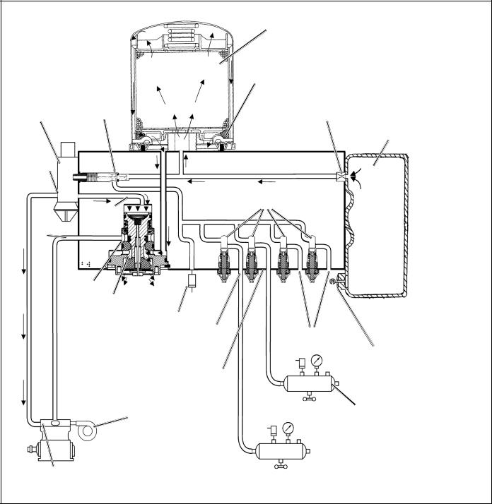
The function of the Integrated Solution Air Dryer (AD-IS®) |
|
|
|
|
|
|
|||||
1 |
|
|
|
|
|
||||||
and Reservoir System is to provide heavy vehicles with an |
|
Inlet Port (air in). |
|
|
1 |
||||||
IN |
|
|
|
||||||||
integrated vehicle air dryer, purge reservoir, governor and a |
21 |
|
|
|
|
|
|||||
number of the charging valve components in a module. |
|
Delivery Port out (to Primary reservoir) |
|
1 |
|||||||
PRI |
|
|
|||||||||
These have been designed as an integrated air supply |
|
|
|||||||||
22 |
|
|
|
|
|
||||||
system. |
|
|
|
|
|
|
Delivery Port out (to Secondary reservoir) |
|
|
||
|
|
|
|
|
SEC |
|
|
1 |
|||
|
|
|
|
|
|
|
|
||||
The AD-IS® air dryer and reservoir system collects and |
24 |
|
|
|
|
|
|||||
removes air system contaminants in solid, liquid and vapor |
|
Auxiliary Delivery Port (air out). |
|
4 |
|||||||
AUX 1 |
|
|
|||||||||
form before they enter the brake system. It provides clean, |
|
|
|
|
|
||||||
23 |
|
|
|
|
|
||||||
dry air to the components of the brake system which |
|
Auxiliary Delivery Port (air out). |
|
1 |
|||||||
AUX 2 |
|
|
|||||||||
increases the life of the system and reduces maintenance |
|
|
|||||||||
|
|
|
|
|
|||||||
|
|
|
|
|
|
||||||
costs. |
The necessity for daily manual draining of the |
UNL |
|
Unloader Control Air (D-2A™ Governor) |
|
2 |
|||||
reservoirs is eliminated. |
|
|
|
RES |
|
Common Reservoir Pressure |
|
2 |
|||
|
|
|
|
|
|
|
|
(D-2A™ Governor) |
|
|
|
|
|
|
|
|
|
EXH |
|
Governor Exhaust |
|
|
1 |
|
|
|
|
|
|
|
|
|
|
|
|
TABLE 1 - PORT DESIGNATIONS
1

DESICCANT
BED
DELIVERY GOVERNOR CHECK
VALVE (OPEN)
UNLOADER
PORT
PURGE
CONTROL
CHANNEL
OIL
SEPARATOR
PRESSURE PROTECTION
VALVES
A
Note 1:
The AD-IS® air dryer and reservoir system purge piston has a purge control channel drain. This allows any condensation in this area to flow past a diaphragm in the top of the purge piston and out through a channel in the middle of the central bolt of the purge assembly to be drained. During the purge cycle this drain is closed.
PURGE |
PURGE |
|
ORIFICE |
||
RESERVOIR |
||
|
INLET |
|
|
|
|
B |
C |
D |
PORT |
|
|
|
|
|
|
|
(IN) |
TURBO CUT- |
|
|
|
|
|
|
|
|
|
|
|
|
||
|
|
|
|
|
|
|
|
|
OFF VALVE |
|
|
|
|
|
|
|
|
|
|
|
|
|
|
|
(OPEN) |
|
|
SAFETY |
|
|
|
|
PURGE |
SEE |
|
|
|
||
|
VALVE |
|
|
|
|||
|
VALVE |
|
|
|
|||
|
NOTE 1 |
PRIMARY |
|
|
|
||
|
(CLOSED) |
|
|
|
|||
|
|
|
|
PORT |
|
AUXILIARY PORTS |
|
|
|
|
|
(PRI) |
|
||
|
|
|
|
|
(TO ACCESSORIES) |
||
|
|
|
|
|
|
||
|
|
|
|
|
|
|
PURGE |
|
|
|
|
SECONDARY |
|
|
RESERVOIR |
|
|
|
|
PORT |
|
|
DRAIN VALVE |
|
|
|
|
(SEC) |
|
|
|
ENGINE
TURBO
 COMPRESSOR
PRIMARY
RESERVOIR
SECONDARY
RESERVOIR
DIAGRAM SHOWS PRESSURE PROTECTION VALVES A & B OPEN, C & D CLOSED.
FIGURE 2 - AD-IS® AIR DRYER AND RESERVOIR SYSTEM CHARGE CYCLE
The function of the pressure protection valves is to protect each reservoir from a pressure loss in the other reservoir or a pressure loss in an air accessory. Each of the pressure protection valves in the AD-IS® air dryer and reservoir system may have different pressure settings, but these are factory set and must not be changed or adjusted.
The air dryer and reservoir system consists of a “spin on” desiccant cartridge secured to a base assembly. The base assembly contains a delivery check valve assembly, safety valve, heater and thermostat assembly, pressure protection valves, threaded air connections and the purge valve assembly.
The removable purge valve assembly incorporates the purge valve mechanism and a turbocharger cut-off feature that is designed to prevent loss of engine “turbo” boost pressure during the purge cycle of the AD-IS® air dryer and reservoir system. For ease of maintenance, all replaceable assemblies can be serviced without removal of the air dryer and reservoir system from its mounting on the vehicle. Refer to Preventive Maintenance section.
2
DESICCANT
BED
DELIVERY
CHECK
VALVE
GOVERNOR (CLOSED)
UNLOADER
PORT
INLET |
PURGE |
|
CONTROL |
||
PORT |
||
CHANNEL |
||
(IN) |
||
|
TURBO CUT-
OFF VALVE EXHAUST (CLOSED) PURGE
VALVE (OPEN)
ENGINE
TURBO
 COMPRESSOR
GOVERNOR SIGNALS AIR
COMPRESSOR TO SUSPEND
COMPRESSED AIR SUPPLY
TO AD-IS® AIR DRYER
SAFETY VALVE
OIL
SEPARATOR
PURGE
ORIFICE
PURGE
RESERVOIR
PRESSURE PROTECTION
VALVES
A
B C D
PRIMARY |
AUXILIARY PORTS |
|
PORT |
||
(TO ACCESSORIES) |
||
(PRI) |
||
|
PURGE
RESERVOIR
DRAIN VALVE
SECONDARY
PORT (SEC)
SECONDARY
RESERVOIR
PRIMARY
 RESERVOIR
DIAGRAM SHOWS ALL PRESSURE PROTECTION VALVES OPEN.
FIGURE 3 - AD-IS® AIR DRYER AND RESERVOIR SYSTEM PURGE CYCLE
AD-IS® AIR DRYER AND RESERVOIR SYSTEM OPERATION: GENERAL (Refer to Figure 2)
The AD-IS® air dryer and reservoir system is designed to receive compressed air from the vehicle air compressor, clean and dry the air, deliver air to the vehicle’s primary reservoir, secondary reservoir and accessories, and control the compressor/dryer charge cycle.
AIR DRYER AND RESERVOIR SYSTEM OPERATION: GENERAL
The AD-IS® air dryerand reservoir system alternates between two operational modes or “cycles” during operation: the
Charge Cycle and the Purge Cycle. The following descriptions are separated into these “cycles” of operation.
CHARGE CYCLE (Refer to Figure 2)
When the compressor is loaded (compressing air) compressed air flows through the compressor discharge line to the inlet (1/IN) port of the air dryer body. The compressed air often includes contaminates such as oil, oil vapor, water and water vapor.
Traveling through the discharge line and into the air dryer, the temperature of the compressed air falls, causing some
3
of the contaminants to condense and drop to the bottom of the air dryer and reservoir system purge valve assembly, ready to be expelled at the next purge cycle. The air then flows into the desiccant cartridge, where it flows through an oil separator which removes liquid oil and solid contaminants.
Air then flows into the desiccant drying bed and becomes progressively drier as water vapor adheres to the desiccant material in a process known as “ADSORPTION.”
Dry air exits the desiccant cartridge through the center of the base assembly. The air then flows to the delivery check valve and also through an orifice into the purge reservoir. The delivery check valve opens, supplying air to the pressure protection valves (A) through (D) simultaneously, the safety valve, and also to the reservoir port of the attached governor. The purge reservoir fills, storing air that will be used to reactivate the desiccant during the purge cycle. This air is available to supply downstream components during the charge mode.
When the air pressure reaches approximately 106 psi, the four pressure protection valves will open and air will be supplied to the primary reservoir, secondary reservoir and accessories. If the pressure protection valves are preset to different values the valves will open in order of lowest setting to highest setting when charging a flat system.
The air dryer and reservoir system will remain in the charge cycle until the air brake system pressure builds to the governor cut-out setting of approximately 130 p.s.i.
PURGE CYCLE (Refer to Figure 3.)
When air brake system pressure reaches the cut-out setting of the governor, the governor unloads the compressor and the purge cycle of the air dryer and reservoir system begins.
The governor unloads the compressor by allowing air pressure to fill the line leading to the compressor unloader mechanism - causing the delivery of compressed air to the AD-IS® air dryer and reservoir system to be suspended.
Similarly, the governor also supplies air pressure to the AD-IS® air dryer and reservoir system purge control channel. The AD-IS® air dryer and reservoir system purge piston moves down in response to this air pressure, causing the purge valve to open to the atmosphere and the turbo cut-off valve to close off the supply of air from the compressor (this will be further discussed in the Turbo Cut-off Feature section). Water and contaminants which have collected in the purge valve base are expelled immediately when the purge valve opens. Also, air which was flowing through the desiccant cartridge changes direction and begins to flow toward the open purge valve. Oil and solid contaminants collected by the oil separator are removed by air flowing from the purge reservoir through the desiccant drying bed to the open purge valve.
The initial purge and desiccant cartridge decompression lasts only a few seconds and is evidenced by an audible burst of air at the AD-IS® air dryer and reservoir system exhaust.
The actual reactivation of the desiccant drying bed begins as dry air from the purge reservoir flows through the purge orifice into the desiccant bed. Pressurized air from the purge reservoir expands after passing through the purge orifice; its pressure is lowered and its volume increased. The flow of dry air through the drying bed reactivates the desiccant material by removing the water vapor adhering to it. Approximately 30 seconds are required for the entire contents of the purge reservoir of a standard AD-IS® air dryer and reservoir system to flow through the desiccant drying bed.
The delivery check valve assembly prevents air pressure in the brake system from returning to the air dryer and reservoir system during the purge cycle. After the purge cycle is complete, the air dryer and reservoir system is ready for the next charge cycle to begin.
TURBO CUT-OFF FEATURE (Refer to Figure 3.)
The primary function of the turbo cut-off valve is to prevent loss of engine turbocharger air pressure through the AD-IS® air dryer and reservoir system when the dryer is in the unloaded mode.
At the onset of the purge cycle, the downward travel of the purge piston is stopped when the turbo cut-off valve (tapered portion of purge piston) contacts its mating metal seat in the purge valve housing. With the turbo cut-off valve seated (closed position), air in the compressor discharge line and AD-IS® air dryer and reservoir system inlet port cannot enter the air dryer and reservoir system. In this manner the turbo cut-off effectively maintains turbo charger boost pressure to the engine.
PREVENTIVE MAINTENANCE
Important: Review the warranty policy before performing any intrusive maintenance procedures. An extended warranty may be voided if intrusive maintenance is performed during this period. Purge valve maintenance is permissible during the warranty period only when using a genuine Bendix purge valve kit.
Because no two vehicles operate under identical conditions, maintenance and maintenance intervals will vary. Experience is a valuable guide in determining the best maintenance interval for any one particular operation.
Every 900 operating hours, or 25,000 miles or three (3) months:
1.Check for moisture in the air brake system by opening reservoir drain valves and checking for presence of water. If moisture is present, the desiccant cartridge
4
may require replacement; however, the following conditions can also cause water accumulation and should be considered before replacing the desiccant:
A.An outside air source has been used to charge the system. This air did not pass through the drying bed.
B.Air usage is exceptionally high and not normal for a highway vehicle.
This may be due to accessory air demands or some unusual air requirement that does not allow the compressor to load and unload (compressing and non-compressing cycle) in a normal fashion. Check for high air system leakage. If the vehicle vocation has changed it may be necessary to upgrade the compressor size. Refer to Bendix Specification BW-100-A, Appendix D to determine if any changes are necessary.
C.Location of the air dryer and reservoir system is too close to the air compressor. Refer to Bendix Specification BW-100-A, Appendix B for discharge line lengths.
D.In areas where more than a 30 degree range of temperature occurs in one day, small amounts of water can temporarily accumulate in the air brake system due to condensation. Under these conditions, the presence of small amounts of moisture is normal.
Note: A small amount of oil in the system is normal and should not be considered as a reason to replace the desiccant cartridge. Some oil at the dryer exhaust is normal.
2.Visually check for physical damage such as chaffed or broken air and electrical lines and broken or missing parts.
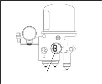
3.Check the AD-IS® air dryer and purge reservoir bolts for tightness. See Figure 1. Re-torque the three air dryer bolts to 360-420 inch pounds and the four purge reservoir bolts to 300-360 inch pounds.
4.Perform the Operation & Leakage Tests listed in this publication.
WARNING!
This air dryer and reservoir system is intended to remove moisture and other contaminants normally found in the air brake system. Do not inject alcohol, anti-freeze, or other de-icing substances into or upstream of the air dryer and reservoir system. Alcohol is removed by the dryer, but reduces the effectiveness of the device to dry air. Use of these or other substances can damage the air dryer and reservoir system and may void the warranty.
HEATER & THERMOSTAT
CONNECTOR
FIGURE 4 - AD-IS® AIR DRYER AND RESERVOIR SYSTEM
HEATER AND THERMOSTAT CONNECTOR
OPERATION & LEAKAGE TESTS (ALSO SEE VIDEO BW2327)
1.Check all lines and fittings leading to and from the air dryer and reservoir system for leakage and integrity. Repair any leaks found.
2.Build up system pressure to governor cut-out and note that the AD-IS® air dryer and reservoir system purges with an audible escape of air. Watch the system pressure and note the pressure fall-off for a ten minute period. If pressure drop exceeds, for a single vehicle - 1 psi/minute from either service reservoir; or for tractor trailer - 3 psi/minute from either service reservoir, inspect the vehicle air systems for sources of leakage and repair them. Refer to section entitled Troubleshooting, Symptoms 1 and 4.
3.Caution: Be sure to wear safety glasses in case of a purge blast. Check for excessive leakage around the purge valve with the compressor in the loaded mode (compressing air). Apply a soap solution to the purge valve exhaust port and observe that leakage does not exceed a 1" bubble in 1 second. If the leakage exceeds the maximum specified, refer to section entitled
Troubleshooting, Symptom 4.
4.Build up system pressure to governor cut-out and note that the AD-IS® air dryer and reservoir system purges with an audible burst of air, followed immediately by approximately 30 seconds of air flowing out of the purge valve. "Fan" the service brakes to reduce system air pressure to governor cut-in. Note that the system once again builds to full pressure and is followed by an AD-IS® air dryer and reservoir system purge. If system does not follow this pattern, refer to section entitled
Troubleshooting, Symptoms 5 and 6.
5.Check the operation of the end cover heater and thermostat assembly during cold weather operation as follows:
5
 Loading...